

Tyco Safety Canada 05SKYCL User Manual
Universal Wireless Communicator
Compatible with all PowerSeries keypads
Installation & Programming Guide
ver 1.2
CL3050
WARNI NG: This manual contains information on limitations regarding product use
and function and information on the limitations as to liability of the manufacturer.
Read the entire manual carefully.

Location
Test Time & Day
Additional Notes
For Your Records
CONNECT 24
Note: Only authorized dealers can enroll a wireless system to Connect 24.
TM
Enrollment Information
Dealer application forms and additional information on the Connect 24 Voice
Response Unit can be found at the Connect 24 web site.
http://www.connect24.com/dealer.htm
The information required for activation is listed below. Ensure that all information
is available before calling the Connect 24 Voice Response Unit.
USA 1-888-251-7458 CAN 1-888-955-5583
Profile Number ...................................................5 digits I___I___I___I___I___I
The profile number provides Central Station Receiver information.
Installer ID Number............... 8-9 digits I___I___I___I___I___I___I___I___I___I
An Installer ID number was provided for each installer listed on the Dealer
Enrollment Form. This number can be found on the authorized Installer Card
sent with the Dealer Confirmation Form.
Installer PIN Number................................................ 4 digits I___I___I___I___I
Each Installer provided a 4 digit PIN number on the Dealer Enrollment Form. If
you have forgotten your PIN Number contact Connect 24.
Central Station Account number ............ 2-6 digits I___I___I___I___I___I___I
This is the Account Number that will be sent to the Central Station.
NOTE: 4-digits maximum for Contact ID format.
Skyroute MIN....................10 digits I___I___I___I___I___I___I___I___I___I___I
The Skyroute Mobile Identification Number identifies the Skyroute transmitter.
The 10-digit MIN is located on the label affixed to your Skyroute Transmitter.
System ID Number (SID)................................5 digits I___I___I___I___I___I
The System ID Number informs Connect 24 and the cellular network the home
area that your transmitter is installed in. When this number is programmed into
an alarm panel it is entered in HEX format. When entering this number into the
Connect 24 Voice Response Unit, it is entered in Decimal Format.

Table of Contents
Section 1: Introduction............................................................................ 1
1.1Specifications.......................................................................................................... 2
1.2Unpacking .............................................................................................................. 2
Section 2: Quick Start.............................................................................. 3
2.1Installation.............................................................................................................. 3
2.2Testing .................................................................................................................... 4
2.3Resetting to Factory Defaults .................................................................................. 4
Section 3: Controls & Indicators ............................................................. 5
3.1LED Indicators......................................................................................................... 5
3.2Enroll Button........................................................................................................... 6
3.3Terminal Connections.............................................................................................. 6
Section 4: Power up Sequence ............................................................... 7
Section 5: System Programming ............................................................ 8
Section 6: Programming Descriptions.................................................... 8
[01]Zone 1-2 Definitions ..............................................................................................8
[02]Zone 3-8 Definitions ..............................................................................................9
[03]Zone 1-2 Loop Response........................................................................................ 9
[10]Skyroute CL3050 Mode of Operation..................................................................... 9
[11]Skyroute CL3050 Configuration Options 1........................................................... 10
[12]Skyroute CL3050 Configuration Options 2........................................................... 11
[13]Skyroute CL3050 Trouble Output Mask................................................................ 11
[15]System Time ........................................................................................................12
[16]System Day.......................................................................................................... 13
[17]Test Transmission Time .........................................................................................13
[18]Test Transmission Day........................................................................................... 13
[20]Transmission Options ........................................................................................... 13
[21]System Event Communication Options................................................................. 15
[22]Input Supply Fail Tx Delay .................................................................................... 15
[23]Generic Zone Reporting Timer ............................................................................. 15
[24]Number of Attempts............................................................................................ 15
[25]Response Wait Time............................................................................................. 15
Section 7: Programming Worksheets................................................... 16
Glossary of Terms .................................................................................. 20
Appendix A: Reporting Codes.............................................................. 22
i

NOTE:
ii
Introduction
Section 1: Introduction
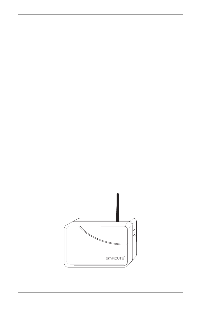
The Skyroute CL3050 is a standalone wireless communicator that sends alarm system information to Connect 24. Connect 24 then forwards this information to the central station.
The Skyroute CL3050 has four modes of operation. It can operate in one of three operational modes or; if it is connected to a keypad, in the programming mode. The Skyroute
CL3050 is pre-programmed with the most commonly used settings for quick installation. If
required the default options can be custom programmed.
NOTE: For UL Installations, use mode 2 or 3 ONLY.
Mode 1: Bell Follower
In Mode 1, the Skyroute CL3050 monitors the Bell Output of the control panel.
The system identifies the Bell Output cadence and transmits the corresponding
Fire or Burglar alarm reporting code to Connect 24.
Refer to the appropriate control panel Installation Manual.
NOTE: Not for UL Listed installations.
Mode 2: 2-Zone Panel
In Mode 2, the system will configure itself for 2 zone, stand alone operation.
NOTE: UL Listed for residential burglary installations ONLY.
Mode 3: 8-Zone Panel
If the Skyroute CL3050 detects a PC5108 expander card on power up it will automatically configure itself for 8-zone standalone operation with normally closed
loops.
NOTE: Standalone operation is intended for household fire and burglary and it is
considered ancillary operation for commercial fire and burglary installations.
Programming Mode
If the Skyroute CL3050 detects a keypad on power up it will go into the programming mode. Programming mode allows the installer to custom program system
options. Refer to Section 5, Programming Descriptions; and Section 6, Programming Worksheets for programming options and default settings.
Figure 1
CL3050
1

Introduction
1.1 Specifications
• Power Supply Ratings
• Current Drain
• RF Power Output: 600 mW
• Antenna Gain: 0 db
• Battery
• Operating Modes
• Event Buffer (communications): 32 Events (not viewable)
• Dimensions: 5 1/8” x 7 3/4” x 2”
• Weight: 0.5 lbs. (0.2Kg)
• EEPROM Memory
• Programmable by all PowerSeries Keypads
Voltage: 10.6-14 V
AC or VDC
Current: 500 mA (Max)
Low DC Trouble: 8.8 V
DC
Low DC Restore: 9.0 VDC
Low AC Trouble: 7.5 V
Low AC Restore: 8.0 V
AC
AC
Standby: 100 mA
Receiving: 150 mA
Transmitting: 850 mA (350 mA from external power supply)
Charging Voltage: 6.87 V
Low Battery Restore: 5.87 V
DC
DC
Low Battery Trouble: 5.72 VDC
Critical Shutdown: 5.0 VDC
Bell Follower
2-24Hr Zones
8-24Hr zones (with PC5108)
PC5508/KP5508Z: 8 Zone LED keypad
PC5516Z/KP5516Z: 16 Zone LED keypad
PC5532Z/KP5532Z: 32 Zone LED keypad
LCD5500Z/KPL5500Z: Programmable Message LCD Keypad
LCD5501Z/KP5501Z: Fixed Message LCD Keypad
1.2 Unpacking
Verify that the following items have been included.
Skyroute CL3050 (rechargeable battery included)
1
Installation & Programming Guide
1
Antenna
1
Mounting screws
4
5.6KΩ resistors
4
Enclosure screw
1
Remove antenna from protective bubble pack and install in unit.
CAUTION: Install antenna before connecting battery or power leads to this unit. Transmission without an antenna can cause permanent damage.
When removing cover of this unit DO NOT touch or handle exposed electrical devices and
components. Electrostatic discharge (ESD) can permanently damage this unit or reduce the
reliability and life expectancy of components.
2

Skyroute CL3050 Universal Wireless Communicator
Section 2: Quick Start
2.1 Installation
1 Determine The Operating mode required
The operating mode (modes 1, 2, or 3) will determine how the unit is to be wired
up. Refer to section 6, Programming Descriptions, section [10] for available
options and for programming defaults. See section 4, Power up Sequence for
selection of Operating and Programming modes.
NOTE: For UL Installations, use only mode 2 or 3.
2 Determine the Mounting Location
Select a mounting location in a dry, protected area. The mounting location
should be positioned so that it is at least 30 cm. away from physical contact with
any person.
NOTE: Do Not exceed the following recommendations for wire run distances
• Keybus and zone wiring should be run using minimum 22 gauge quad
(0.5mm). Two pair twisted is preferred.
• a keypad, PC5108, or zone wiring can not exceed 1,000'/305m (in wire
length) from the Skyroute CL3050.
• Shielded wire is not necessary unless wires are run in an area that may present
excessive RF noise or interference.
• Refer to section 6, Programming Descriptions, section [10] for zone wiring details.
NOTE: Generally, the higher the location and the closer that the Skyroute CL3050
is to an outside wall, the better the signal strength will be.
3 Checking Signal Strength
•Remove front cover
• Connect Battery to the RED and BLK flying leads.
• Connect AC Power source or 12 V
• Allow unit to power up
NOTE: The unit does not need to be enrolled with Connect 24 to check signal
strength.
• When the green LED stops flashing, press and release the enroll button.
• Ensure that Radio Signal Strength Indication (RSSI) is greater than the mini-
mum acceptable level as indicated below. If the signal level is not acceptable, reposition and retest the Skyroute CL3050 until an acceptable signal
strength is found.
Red LED Yellow LED Green LED Signal Strength
On
On
On
On
On
Flash
*Minimum recommended signal strength for enrollment
4 Route Wiring to Mounting Location
Route wiring from the hardwired zones or control panel as required.
NOTE: Route wiring through conduit to a junction box if possible. Mount the
Skyroute Panel.
On
On
On
Flash
Off
Off
DC
to RED & BLK terminals.
On
Flash
Off
Off
Off
Off
>87%
69-87%
*52-68%
34-51%
16-33%
0-15%
3

5 Mount Unit
• Remove the front cover if required
• Disconnect flying leads from battery and power leads from the RED and BLK
terminals (if connected).
• Remove two screws securing battery clamp. Remove battery
• Mount backplate of unit to wall or over electrical junction box using the
four screws provided.
NOTE: DO NOT connect the battery to the flying leads and AC or DC power to
the terminal strip until all other wiring connections are completed.
• Route wiring through the access holes provided and connect to terminal
strip.
• Power up unit by connecting battery and power source.
• Front cover is to be securely fastened with screw provided.
6 Enroll Unit
Call Connect 24 and Enroll the Skyroute CL3050. Refer to back of Front Cover
for contact information and a list of information required to complete the enrollment with the Connect 24 Voice Response Unit.
2.2 Testing
Program Mode: If you have wired the unit to power up in the programming
mode. Follow the steps outlined in Section 6, Programming Descriptions and
record the program settings in Section 7, Programming Worksheets.
Test Transmission - Pressing and holding the enroll button for 2 seconds will
send a test transmission to the central station via Connect 24. Refer to Enroll
Button in Section 3, Controls and indicators for test transmission details.
Mode 1: Disable the telephone line connected to the control panel. Simulate
Burglar and Fire Zone violation. Verify that the Skyroute CL3050 transmits the
events to the central station.
Mode 2 & 3: Simulate Faults, Tampers, and Zone violations in accordance with
the settings outlined in Sections 6, Programming Descriptions. Verify that the
Skyroute CL3050 transmits the events to the central station.
2.3 Resetting to Factory Defaults
NOTE: Resetting to factory defaults is required to change mode of operation.
• Remove Power from the Skyroute CL3050; disconnect battery and control
panel if applicable (mode 1).
• Disconnect all wiring from the YEL and GRN terminals.
• Connect a jumper wire between the YEL and GRN terminals.
• Apply power to the system.
NOTE: When the hardware default has been completed; the yellow, green and
red LEDs will flash on and off continuously.
• Remove power from the system.
NOTE: To resume communications with Connect 24, Section [11], Option 6
must be set to ON. To do this; the system must be powered up in programming
mode. Refer to Section 5 System Programming.
• Reconnect all original wiring and reapply power to the system.
• Test System - Refer to Section 2.2
Quick Start
4
Skyroute CL3050 Universal Wireless Communicator
Section 3: Controls and Indicators
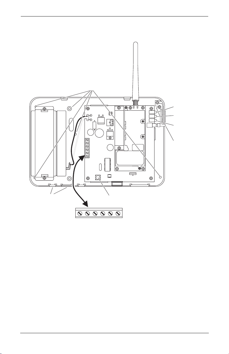
Figure 2
Antenna
Mounting Holes
Battery (6 VDC)Battery (6 V )
1.3 Ah
DC
SW1
SW2
Green LED
Yellow LED
Red LED
Enroll Button
Wire Access
RED BLK YEL GRN COM PGM
Tamper Switch
3.1 LED Indicators (see figure 2)
Yellow LED
During normal operation, the yellow LED will indicate the system status with a
series of flashes as indicated below.
No. of
Flashes Indication
No trouble conditions present
1
Low battery
2
Input supply failure
3
Not enrolled at Connect 24
4
No service available
5
Radio failure
6
PC5108 failure
7
Failure to communicate
8
Zone tamper/fault trouble
9
5
 Loading...