

Tyco Safety Canada 05SKY User Manual
Q
ui
ck
le
P
de
ui
G
l
al
t
s
n
I
e
s
a
p
e
e
s
1
e
g
a
Installation Manual
WARNING
product use and function and information on the limitations as to
liability of the manufacturer. The entire manual should be carefully read.
: This manual contains information on limitations regarding
version 2.4

Table of Contents
SKYROUTE QUICK INSTALL GUIDE 1
Section 1 - Contents 2
1.1 Important Information .............................................................. 2
1.2 Skyroute Transceiver Glossary of Terms ................................ 2
Section 2 - What is it? 2
2.1 Introducing the Skyroute Transceiver ...................................... 2
2.2 Specifications ........................................................................... 2
Section 3 - How Does It Work? 3
3.1 Cellemetry Communication ..................................................... 3
3.2 Skyroute Reporting Methods ................................................... 3
Section 4 - What Do I Do before Installing a
Skyroute Transceiver? 5
Section 5 - Installing a Skyroute Transceiver 6
5.1 Location of the Skyroute Unit ................................................. 6
5.2 Relocating the Skyroute Transceiver ....................................... 6
5.3 Relocating the Antenna ............................................................ 6
5.4 UL Requirements ..................................................................... 7
5.5 Installation ............................................................................... 8
5.6 Mounting the Skyroute Transceiver ........................................ 8
5.7 Mounting the Antenna .............................................................. 8
5.8 Keybus Connection .................................................................. 8
5.9 Bell IN Terminal ...................................................................... 8
5.10 Bell OUT Terminal ................................................................. 8
5.11 Tamper Terminal ....................................................................8
5.12 Secure Installation .................................................................. 8
5.13 Connection Diagrams .............................................................8
5.14 Wiring Skyroute to a DSC/Partner Control Panel ................11
5.15 Supervised Power Supply Connection .................................11
Section 6 - Programming and Activating a Skyroute 12
6.1 Defaulting ............................................................................... 12
6.2 Programming Options ............................................................12
6.3 Activating a Skyroute Transceiver ......................................... 13
Section 7 - [803] Skyroute Programming Worksheets 14
7.1 Defaulting ............................................................................... 14
7.2 Basic Programming ................................................................ 14
7.3 Advanced Programming......................................................... 16
Section 8 - Testing 25
Section 9 - Troubleshooting 25
Section 10 - For Your Records 26
Appendix A: Reporting Codes 27
Appendix B: Zone Alarms/Restorals 29
Appendix C: Tamper Alarms /Restorals 31
Appendix D: Decimal - Hex - Binary Conversion 32
FCC COMPLIANCE STATEMENT
CAUTION: Changes or modifications not expressly approved by Digital Security Controls Ltd. could void your authority to use this equipment.
This equipment has been tested and found to comply with the limits for a Class B digital device, pursuant to Part 15 and Part 22 of the FCC Rules. These limits are designed to provide reasonable
protection against harmful interference in a residential installation. This equipment generates, uses and can radiate radio frequency energy and, if not installed and used in accordance with the
instructions, may cause harmful interference to radio communications. However, there is no guarantee that interference will not occur in a particular installation. If this equipment does cause
harmful interference to radio or television reception, which can be determined by turning the equipment off and on, the user is encouraged to try to correct the interference by one or more of the
following measures:
• Re-orient the receiving antenna.
• Increase the separation between the equipment and receiver.
• Connect the equipment into an outlet on a circuit different from that to which the receiver is connected.
• Consult the dealer or an experienced radio/television technician for help.
The user may find the following booklet prepared by the FCC useful: “How to Identify and Resolve Radio/Television Interference Problems”. This booklet is available from the U.S. Government
Printing Office, Washington D.C. 20402, Stock # 004-000-00345-4.
FCC ID: F5305SKY
INDUSTRY CANADA COMPLIANCE STATEMENT
This Class B digital apparatus meets all requirements of the Canadian interference-causing equipment regulations.
Cet appareil numérique de la Classe B respecte toutes les exigences de règlement sur le matériel brouilleur du Canada.
IC: 160A-05SKY
The term “IC:” before the radio certification number only signifies that Industry Canada technical specifications were met.
WARNING: To satisfy FCC RF exposure requirements for mobile
transmitting devices, a separation distance of 30 cm or more
should be maintained between the antenna of this device and
persons during device operation. To ensure compliance, operation at closer than this distance is not recommended.
NOTE:The reference to "Skyroute" throughout this manual is applicable
to the following model numbers: Skyroute and Skyroute (A).

SKYROUTE QUICK INSTALL GUIDE
IMPORTANT: You must be enrolled with CONNECT 24 to activate a Skyroute transceiver. If you are not
already enrolled, please call 1-888-955-5583 in Canada or 1-888-251-7458 in the U.S. at least 24 hours
prior to your first activation.
STEP 1 – DETERMINE BEST SIGNAL LOCATION
Connect the Skyroute transceiver to a 7 Ah battery, as described in Section 5.1. Determine the best location for signal strength. If good signal
strength cannot be found, an antenna extension or relocation may be required.
STEP 2 – CONNECT THE SKYROUTE TO THE PANEL
Mount and connect the Skyroute to the control panel as shown in Section 5.13.
STEP 3 – PROGRAM THE SKYROUTE
Enter *8 + Installer Code to enter Programming Mode. Go to section [803], and program the following sections:
DEFAULT THE SKYROUTE - Section [99]
Select the Default option as described in Section 6.1 of this manual:
• For FULL REPORTING……………….enter 00 into Section [99]
• For FALLBACK REPORTING….….....enter 11 into Section [99]
• For GENERIC REPORTING………..…enter 12 into Section [99]
• For BACKUP REPORTING………..…enter 03 into Section [99]
The Skyroute module will automatically restart, and default to the new setting.
PROGRAM THE ZONE DEFINITIONS - Sections [01] through [04]
• Program the Zone Definitions as described in Section 6.2.
SELECT THE CELLULAR CHANNEL - Section [06]
The Skyroute transceiver is defaulted for Channel B. If you require Channel A (see the SID List for the channel of the cellular service provider in your area), perform the following:
• In Section [06], TURN OFF OPTION 2, and TURN ON OPTION 1 (Press # to exit section [06])
• In Section [10], enter the transmission time of day in 24-hour format (HHMM).
NOTE: Due to the volume of wireless traffic generated by test signals, please select a time which is NOT on the :30 minute marks (i.e.,
NOT 02:30, 04:00, etc. Select a time like 02:24, or 04:07, etc. wherever possible.
• In Section [11], select the transmission day of the week.
NOTE: This section is not to be used for UL Listed applications.
• In Section [13], select Daily or Weekly testing as required.
NOTE: Select this option in conjunction with the CONNECT 24 rate plan you are using for this installation. The default setting is
weekly. For UL Listed applications daily test reports are required.
(See Section 6)
(See Section 5.1)
(See Section 5.13)
STEP 4 – ACTIVATE THE SKYROUTE WITH CONNECT 24
Call the Voice Response Unit (VRU) at the toll free number provided with your Dealer Confirmation.
Once activated, send two signals to your
central station to confirm proper operation.
(See Section 6.3)
YOUR SKYROUTE INSTALLATION IS NOW COMPLETE.
ALL OTHER PROGRAMMING SECTIONS IN THIS MANUAL ARE OPTIONAL
1

Section 1 - Contents
1.1 Important Information
This manual is based on the production version of the included
wireless device. Software changes may have occurred after the
revision of this manual.
Caution
Any changes or modifications not expressly approved in this
document could void your warranty for this equipment and
void your authority to use this equipment.
Warni ng
Only use the antenna provided by DSC. The use of any other
type will invalidate the warranty and may be dangerous.
1.2 Skyroute Transceiver Glossary of Terms
The following is a description of various terms used with
respect to cellemetry technology.
Electronic Serial Number (ESN)
The ESN is used to carry data information in a Cellemetry Network
Section 2 - What is it?
2.1 Introducing the Skyroute Transceiver
The Skyroute transceiver offers a new wireless communication
method for the transmission of event information using the
*Cellemetry
route transceiver via the Cellemetry network to the clearing
house and then to the central station in a fast, reliable manner.
The Skyroute receiver has been designed for simple and
straightforward installation. Using Keybus
ing connections are made directly between Skyroute module
and the security control panel.
TM
service. Events are transmitted from the Sky-
TM
technology, wir-
2.2 Specifications
2.2.1 Compatible Control Panels
• DSC PC5010 / Partner P-832 software version v1.XX; v2.X
and higher
• DSC PC1555 / Partner P-6B software version v2.XX and
higher
• DSC PC580 / Partner P-48 software version v2.XX and
higher
• DSC PC5015 / Partner P-832DL software version v1.XX;
v2.2X and higher
• DSC PC5020/PC5020CF / Partner P-8+/P-8+CF software
version v3.2X and higher
2.2.2 Communication Method
• AMPS Control Channel
2.2.3 Dual Path Communications
• The system can be used as the sole method of communication to the central station or as a second transmission path in
addition to the standard land line.
Please contact your central station on dual signal communication.
• Automation system at central station must be able to suppress redundant signals.
Mobile Identification Number (MIN)
A 10-digit decimal number used for registrations and pages.
Page
A transmission that is sent from the Cellemetry Gateway to the
Cellemetry radio.
Registration
A transmission that is sent from the Cellemetry radio to the
Cellemetry Gateway.
System Identification Number (SID)
Identification of the Cellemetry Provider.
Switch Number (SNO)
Switch number the Cellemetry radio uses to transmit pages to
the Cellemetry Gateway.
Clearing House
The clearing house is a routing center that automatically forwards data between Skyroute transmitters and central stations.
2.2.4 Antenna
• 3 dB gain, TNC connector
• Extension Kits available:
LAE - 3: The 3 Foot Antenna Kit for Skyroute Transceiver
LAE - 15: The 15 Foot Antenna Kit for Skyroute Transceiver
LAE - 25: The 25 Foot Antenna Kit for Skyroute Transceiver
SKR - 025: The 25 Foot External Antenna Kit
2.2.5 RF Power Output
• 1.2 Watts maximum
2.2.6 Power Supply Ratings
• 12 VDC @30mA, from panel Keybus; DSC Keybus control
panel required
• 12 V
• For DSC control panels the required minimum transformer is
, from bell circuit
DC
Current in standby 90mA
Current when receiving 135mA
Current when transmitting 1.3A
one rated at 16V
ment is 12VDC 7Ah.
40 VA. The minimum battery require-
AC
2.2.7 Dimension
• 3.5” x 4.6” x 1.8” (85 mm x 115 mm x 45 mm)
2.2.8 Weight
• 0.5 lbs. (0.2 kg)
2.2.9 Operating Temperature
• 0°C - 49°C (32°F - 120°F)
• 85% humidity, non-condensing
*Cellemetry is a registered trademark of Numerex Corporation.
2
Section 3 - How Does It Work?
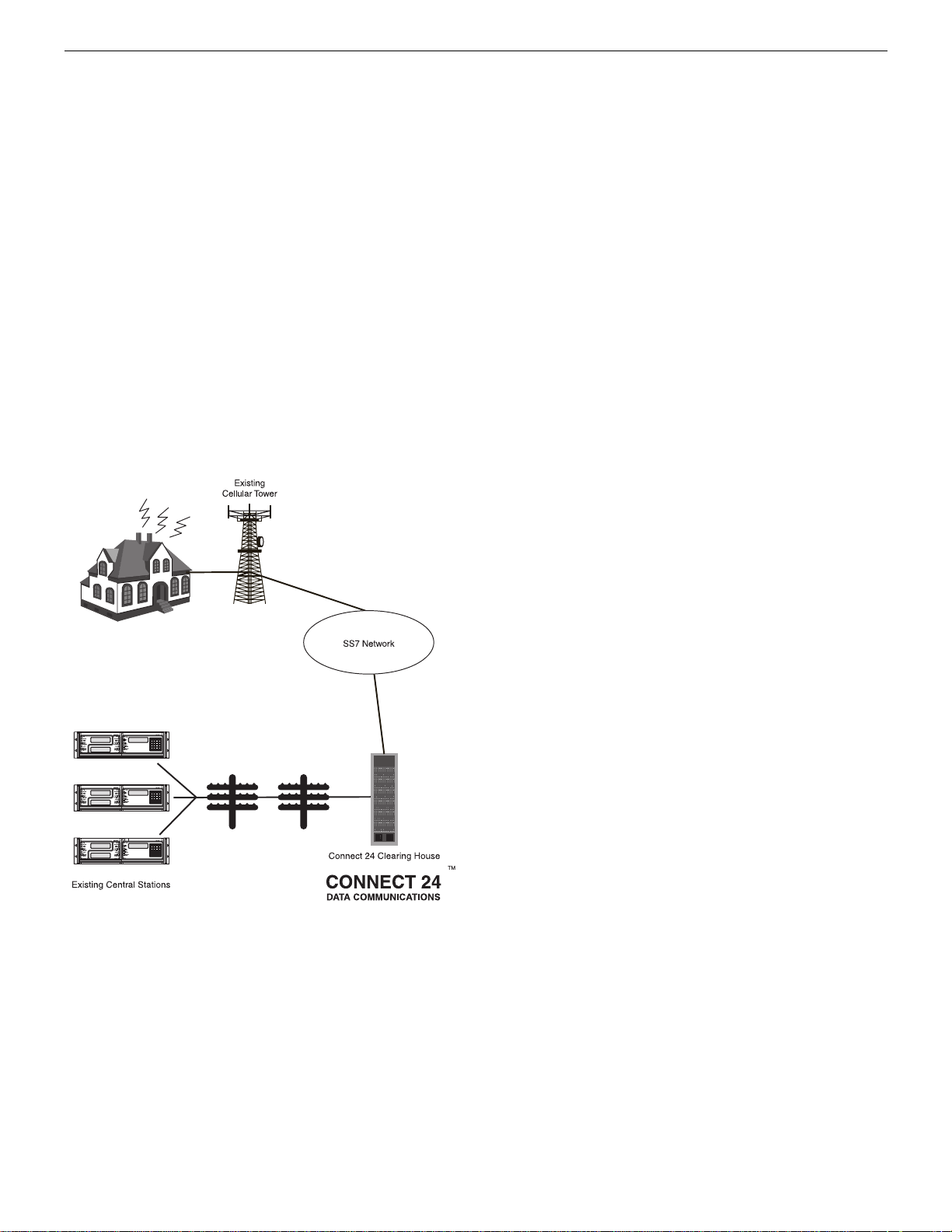
3.1 Cellemetry Communication
The Skyroute transceiver communicates using the control
channel of the existing cellular network. Signals are routed to
the Cellemetry Gateway via the SS7 cellular network. A clearing house then receives the signals and forwards the events to
the central station. Upon receiving an acknowledgement signal
from the central station, the clearing house then returns a confirmation of delivery signal to the Skyroute transceiver over
the network. For transmission sequence see drawing below:
• The Skyroute transceiver reads the system activity directly
from the Keybus. It also sends the corresponding signals
over the cellular network, depending on what you have programmed the Skyroute transceiver to send.
• The Skyroute transceiver can be reprogrammed for full, backup
or generic reporting (see Sections 6.1 and 7.1 ‘Defaulting’).
• The Skyroute transceiver does not consider the signal to be
received at the central station until it receives confirmation
from the clearing house. Relay between signals can be up to
60 seconds apart.
NOTE: While the panel is in walk test mode, the Skyroute will still communicate all alarms.
3.2 Skyroute Reporting Methods
Reporting via Skyroute is in addition to landline communications. Land line communications are unaffected by which
reporting method the Skyroute is using. A default of the Skyroute must be performed before activation (Enter 00, 11 or 22
in sub-section [99] ‘Software Defaulting of the Skyroute’).
This is necessary to configure the Skyroute for one of the four
possible reporting methods:
1: ‘Full Reporting’ (Enter 00 in sub-section [99])
2: ‘Generic Reporting’ (Enter 12 in sub-section [99])
3: ‘Generic Reporting with fallback to Full Reporting’ (Enter
11 in sub-section [99])
4: ‘Backup Reporting’ (Enter 03 in sub-section [99])
Other important things to note:
• For an event to report via the Skyroute, the event reporting
code in sections [30]-[78] must be programmed as [FF] and
the associated ‘Transmission Option’ (in section [22]) must
be enabled.
• To disable a specific event from reporting via the Skyroute,
program the reporting code as [00].
• To disable a group of reporting codes from reporting via the
Skyroute, turn OFF the respective ‘Transmisison Option’ in
section [22].
• The Skyroute does not follow the ‘Event Buffer Follows
Swinger Shutdown’ option in the control panel.
3.2.1 Full Reporting
(Enter 00 in sub-section [99])
All events in sections [30]-[78] are automatically programmed
as [FF] and will be sent by the Skyroute. To disable a specific
event from sending via the Skyroute, program the reporting
code as [00]. To disable a group of reporting codes from sending via the Skyroute, Turn OFF the respective ‘Transmisison
Option’ in section [22].
When using ‘Full Reporting’ it is very important to understand
that when multiple signals need to be sent, there is approximately a one-minute delay between each signal sent via the
Skyroute. Because of this delay, the Skyroute will buffer signals when multiple events occur and transmit them in the order
received.
For example; if you need to send 4 signals (i.e. alarm zone 1,
alarm restore zone 1, alarm zone 2, alarm restore zone 2), it
will take approximately 4 minutes for the Skyroute to send all
4 signals. The first signal sends immediately, then the remaining three signals are each sent approximately 1 minute apart in
the order that they occurred.
When using Full Reporting, the central station will receive the
same signal from the panel via landline communications and
from the panel via Skyroute Communications. This is why it is
important to contact your central station regarding dual signal
communication. The automation system at the central station
must be able to suppress redundant signals.
3.2.2 Generic Reporting
(Enter 12 sub-section [99])
Generic Reporting is used to avoid duplicate alarm signals from
being received at the central station. It also avoids the large
delays between landline signals and Skyroute signals that occur
when multiple events of the same type happen within a short
time period (both of which occur when using ‘Full Reporting’).
Generic reporting only applies to certain types of alarm events.
These events are grouped together into one of 4 categories.
Each category has a specific alarm reporting code. When one
of these alarms occur, the Skyroute will send the associated
alarm reporting code for the category the alarm belongs to –
and then start a timer for that category (5 minutes at default
programmed in section [21]). If another alarm occurs in the
same category while its timer is active, then no signal is generated via the Skyroute for that category. If an alarm occurs in a
different category, then the Skyroute will send the associated
alarm reporting code for that category – and then start a timer
for that category (5 minutes at default – programmed in section
[21]). Each category has it’s own timer. If a new alarm event
occurs after the timer has expired for its category, the sequence
3
restarts. All events that are not included in one of the 4 categories (noted below) will be fully transmitted by the Skyroute (if
the associated reporting codes are programmed and ‘Transmission Options’ are ON).
While in Generic Mode, the panel will group the following
alarm events together as follows:
• Burglary: Delay 1, Delay 2, Instant, Interior, Interior Stay/
Away, Delay Stay/Away, 24 Hour Burglary, 24 Hour Latching Tamper, Momentary Keyswitch Arm, Maintained Keyswitch Arm, Links Answer
• Fire: Delayed Fire, Standard Fire, Delayed Fire (wireless),
Standard Fire (wireless), 2-Wire Smoke (PGM2), Keypad
Fire.
• Supervisory: 24 Hour Supervisory Buzzer, Silent 24 Hr
(PGM2), Audible 24 Hr (PGM2), Zone Expander Supervisory Alarm.
• Panic: 24 Hour Panic, Keypad Panic
Generic Signals
SIA Contact ID
Burglary Partition x Event BA
zone 98
Fire Partition x Event FA
zone 98
Supervisory Partition x Event US
zone 98
Panic Partition x Event PA
zone 98
Partition x Event 130
zone 098
Partition x Event 110
zone 098
Partition x Event 140
zone 098
Partition x Event 120
zone 098
3.2.3 Generic Reporting with Fallback to Full Reporting
(Enter 11 in sub-section [99])
Normally, the Skyroute will use ‘Generic Reporting’ (described
earlier). At any time if the Skyroute receives either a FTC (Failure to Communicate) or a TLM (Telephone Line Monitor) trouble from the main panel via the Keybus, the Skyroute will
switch into ‘Full Reporting’ and send alarm signals as outlined
above in ‘Temporary Full Reporting’ (Note: When using
‘Generic Reporting with Fallback to Full Reporting’ and the
Skyroute switches to ‘Full Reporting’ upon receiving and ‘FTC’
or ‘TLM’ from the panel, the Skyroute will transmit the alarm
signals with the specific zone numbers without restorals).
When the Skyroute switches into ‘Full Reporting’, the FTC or
TLM trouble will be the first signal sent by the Skyroute. For
the Skyroute to switch back into ‘Generic Reporting’, the TLM
or FTC trouble must restore and a signal must be received by
the Skyroute from the main panel via the Keybus.
Upon restoral of the TLM or FTC Trouble, any signals that
occurred before the TLM or FTC trouble restored that still
need to be transmitted will be sent via the Skyroute until the
Skyroute’s communications buffer is empty. In addition, if new
alarms occur after switching back to ‘Generic Reporting’ while
full reporting events are still in the Skyroute’s communication
buffer, the Skyroute will generate the generic signal, place it at
the end of the communication buffer and function as outlined
above for ‘Generic Reporting’.
3.2.4 Backup Reporting
In Backup Reporting mode the Skyroute will only transmit
events when the panel is unable to transmit them. It must be
understood that the potential exists that in some situations
events may be duplicated on the landline, however when the
Skyroute is in backup mode it will attempt to not send events
that can be successfully transmitted over the phone line by the
panel.
Internally in the Skyroute, events are buffered with a timestamp. The timestamp is in intervals of 10 seconds yielding a
maximum time of approximately 42 minutes. The Backup
Timer Section[19] will control how long events will remain in
the buffer before they expire. If an event in the buffer expires
(ie. the timestamp on the event in the buffer is older than the
current timestamp) it will be deleted from the buffer. If an FTC
event is received from the Keybus, all events that have not
expired in the buffer will be transmitted, and the Skyroute will
temporarily go into full reporting mode. The Skyroute will
remain in full reporting mode until an FTC Restore event is
retrieved from the buffer. FTC and FTC Restore will also be
transmitted. The Skyroute will then return to Backup mode.
TLM Trouble and TLM Trouble restore events will always be
transmitted, and any events that are generated by the panel in
between these events will also always be transmitted.
It is important to program the Backup Timer Section [19] to a
Value that correlates to the amount of time it will take for the
panel to FTC. If the panel takes longer to FTC than is programmed in Section [19], then events may expire and no transmission by the Skyroute will occur. If the panel takes less time
to FTC than is programmed into Section [19] then duplicate
events may occur. It is suggested to reduce the panel's number
of dialing attempts to 5 (refer to the Panel's programming), in
order to reduce the time it takes before the Skyroute will
switch into Full Reporting. The following table can be used to
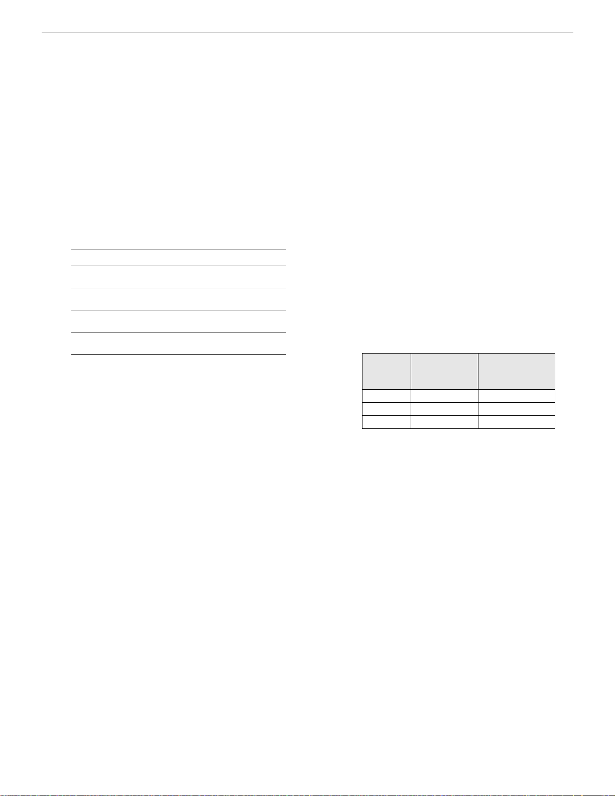
help determine what value should be used in Section [19].
Panel's Max
Dialing
Attempts
Tota l P a nel
Time
Value to Program
into Section [19]
1 90 seconds 09 (9 decimal)
5 450 seconds 2D (45 decimal)
8 720 seconds 48 (72 decimal)
NOTE: This table refers to panel programming, with
the default values for dialing the receiver. If programming has been done in the panel (for example, PostDial Wait for Handshake or Delay Between Dialing
Attempts), then the values used in the Skyroute must
reflect these changes by adding the difference in programmed time to section [19] of the Skyroute.
If the panel is programmed for two phone numbers, then Section [19] should be doubled from what is shown.
The types of events that trigger the Skyroute to temporarily
switch into full reporting mode can be configured in the
Backup FTC options, in Section [18].
NOTE: Do not use backup mode for Commercial Fire
or Commercial Burglary installations. Use only in UL
Residential Fire or Burglary installations.
4

Section 4 - What Do I Do before Installing a Skyroute Transceiver?
CONNECT 24 is your Skyroute Cellemetry service provider.
If you have not yet enrolled as a Skyroute dealer, you must do so at least 1 business day before your first Skyroute installation.
NOTE: If you do not have the numbers required below, please call Connect 24 at 1-888-955-5583 in Canada or 1-888-251-7458
in the U.S. “Dealer Enrolment”.
Activation of your Skyroute transmitter can be accomplished in minutes, at any time 24 hours a day, 365 days a year, by calling our toll-free CONNECT 24 Voice Response Unit at 877-759-7688 (Canada) or 888-251-7554 (U.S.). This guide will provide you with an example of what to
expect when you are using the VRU.
Before you begin, make sure you have all of the information that you will need to enter into the VRU system.
What you will need…
•The Profile Number for your installation
The Profile Number represents the Central Station Receiver/Rate Plan
combination and the communication format you are using. Make sure
that you know which profile number to use when doing an installation.
• Your Installer ID Number
Each individual installer who was listed on your Dealer Enrolment Form
was given a unique Installer ID Number. This number can be found on
the Authorized Installer Card sent with the Dealer Confirmation Form.
• Your Installer PIN
Each installer is provided a four digit Personal Identification Number
(PIN) on the Dealer Enrolment Form. If you have forgotten your PIN,
please contact CONNECT 24.
•The Central Station Account Number for the alarm system
This is the account number you wish to be transmitted to the central station. If the profile is set to send SIA format, enter a maximum of six digits; if Contact ID format, enter a maximum of four digits.
•The Skyroute MIN (Mobile Identification Number)
The MIN identifies the Skyroute transmitter. The 10-digit MIN is
located on the label affixed to your Skyroute transmitter.
•The System ID Number (SID) for the cellular provider in your area
The five-digit System ID Number tells CONNECT 24 (and the cellular
network) the home area in which your transmitter is installed. When you
program this number into the DSC alarm panel, it is entered in HEX format. However, when entering this number into the CONNECT 24 VRU,
it is entered in DECIMAL format.
NOTE: For US locations, please refer to the “U.S.A SID List By State” document which comes with each Skyroute transceiver as a separate booklet.
5
Section 5 - Installing a Skyroute Transceiver
Time-Saving Tips: By powering up the Skyroute transceiver on a battery alone (battery red to Bell In and Keybus red, battery black to
Keybus black), you can quickly determine a location where your signal strength is strong prior to installing the unit. The Skyroute unit
does not have to be active to show signal strength.
5.1 Location of the Skyroute Unit
It is very important to determine the best location for maximum signal strength.
Verify signal strength prior to installation!
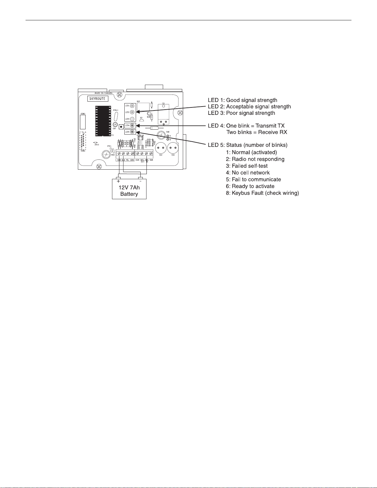
1: Normal (activated) The radio is operating normally and
there are no troubles with the Skyroute.
2: Radio not Responding Possible causes; the radio in the
Skyroute is not powered up, the initialization of cellemetry
radio has failed, an internal problem with the radio, bad data
connections between the radio and the panel.
3: Failed self-test A self-test of the cellemetry module has failed.
4: No cell network The cellemetry modem has failed to regis-
ter with the cellular network (Ie. no network coverage or
very weak signal).
5: Failure to communicate The Skyroute has not successfully
communicated a signal to the central station (the Skyroute
has not received the acknowledgement that the central station successfully received a signal).
6: Ready to Activate The Skyrotue has not been activated
with Connect 24.
8: Keybus Fault The Skyroute cannot communicate to the panel.
NOTE: If there is a Skyroute trouble, the panel it is
connected to will display a ‘General System Supervisory’ trouble.
NOTE: If the [TAM] to [COM] terminals are open on
the Skyroute, the panel it is connected to will display
a ‘General System Tamper’ trouble.
5.2 Relocating the Skyroute Transceiver
Since the Skyroute transceiver is a Keybus accessory, it is possible to relocate the module up to 150 feet (45.4 m) from the
main control panel when the panel is not located in a good Cellemetry coverage area (a control panel installed in a vault for
example). When relocating the module, follow theses rules:
• Maximum of 150 feet (45.4 m) from the main control. Keybus (Red, Black, Yellow, Green) from the panel to the Skyroute transceiver.
• A UL1481 Listed power supply 12V@1.5A must be used for
UL installations.
• The power supply (+ positive) is connected to the Skyroute
transceiver (BELL IN) terminal and the power supply (–
negative) to the Skyroute transceiver (COM) terminal.
• The cabinet must be installed in a secure location and should
have a tamper circuit connected to the Skyroute (TAM and
COM) terminals.
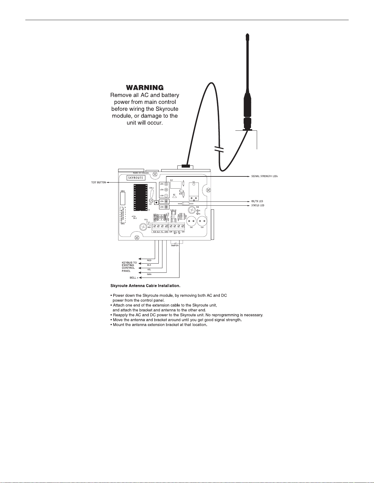
5.3 Relocating the Antenna
If a suitable location is not available for proper Cellemetry coverage, obtain an Antenna Extension Bracket Kit from your DSC
supplier. Each kit contains an extension cable, a mounting
bracket, instructions, and all required hardware. Three lengths of
extension cable are available:
Extension Kit Length of cable
LAE-3 3 feet (0.91 m)
LAE-15 15 feet (4.57 m)
LAE-25 25 feet (7.62 m)
SKR-025 25 feet (7.62m)
Only use the Extension Kits to extend the mounting range
of the antenna. Do not cut or splice the extension cable. The
maximum distance between the Skyroute transceiver and the
antenna is 25 feet (7.62 m) as obtained by using the LAE-25 or
SKR-025 Extension Kit. Make sure the antenna is in a physically secured location to avoid tampering.
Secure the TNC connector from the Extension Kit to the
mounting bracket, ensuring that the star washers make solid
electrical contact with the mounting bracket.
Remove the antenna from the Skyroute module and connect the
extension cable to the TNC connector on the module. Secure the
antenna to the TNC connector mounted on the Extension Kit
mounting bracket. Locate the mounting bracket and antenna away
from possible sources of electrical interference. Moving the
antenna just a short distance will likely be adequate. Temporarily
secure the mounting bracket in the new location and proceed with
testing. If the test is successful, permanently secure the mounting
bracket and antenna at the new location.
6
Antenna Relocation Diagram
Antenna Extension Kits
LAE-3 3-ft. (0.9m) extension kit
LAE-15
LAE-25
SKR-025
15-ft. (4.6m) extension kit
25-ft. (7.6m) extension kit
25-ft. (7.6m) extension kit (external)
5.4 UL Requirements
5.4.1 Grade A - Central Station Service, Residential Fire
and Burglary Installations
• Programming [13] - Option 2 Test Rates must be “ON”.
• Every 24 hours a check-in signal must be sent to the central
station. Refer to compatible Listed control unit’s installation
instructions for programming.
• Dialing attempts must be programmed for 5 to 10 attempts.
Skyroute transmitter makes 3 attempts by default. Refer to
compatible Listed control unit’s installation instructions for
programming.
• The response wait time, section [24] should be set to 09.
• Alarm signals must be sent over both primary and secondary
communication paths -
1. Compatible Listed control unit’s land line to central station (primary).
2. Skyroute transmission through Cellemetry to the clearing
house (Connect 24) (secondary).
• DACT must be enabled for Listed compatible control unit.
5.4.2 Police Station Connect with Basic Line Security
• Same as Grade A Central Station Installations.
5.4.3 Commercial Fire Installations
• Same as Grade A Central Station Installations.
• The BELL+ and BELL- terminals on the control panel shall
not power other devices. Refer to Compatible Listed control
unit installation instructions for wiring and programming.
5.4.4 Back-up Reporting Mode (03)
• To be used only for UL/ULC residential Fire and Burglary
applications.
5.4.5 For ULC Installations
• The redundant Communication mode (00) meets level 2 line
security requirements.
7
5.5 Installation
It is mandatory that the power be removed from the system
before any wiring changes are performed on the Skyroute
module. Neglecting to do so will result in damage to the Skyroute transceiver.
5.6 Mounting the Skyroute Transceiver
The Skyroute transceiver can be mounted in the upper right
hand corner of the panel’s cabinet through the knockout. The
Skyroute transceiver case attaches to the panel’s cabinet
through the use of clips and two screws.
5.9 Bell IN Terminal
This terminal is used to power the Cellemetry modem of the
Skyroute module. This connects to the BELL + on the control
panel. No other wire should be connected to the Bell+ of the
control panel.
An extra power supply can be used to power the modem if it is
not located near the main control panel or is located where the
system cannot provide enough power for the transmissions.
Connect the positive of the power supply to the BELL IN and
the negative to the COM to ensure proper grounding (see diagram on this page).
5.7 Mounting the Antenna
NOTE: The antenna should always be attached to the
Skyroute transceiver for proper operation. The unit will
not function properly and/or be damaged if the
antenna is not installed.
5.10 Bell OUT Terminal
This terminal is used to power the siren or any other devices
that would usually connect to the control panel BELL+ terminal. This output is powered through the 5A fuse for protection
of the radio transmitting power.
The antenna attaches to the TNC connector of the Skyroute
transceiver. The antenna should be mounted as high above
ground level as possible while at the same time care should be
taken not to place the antenna under a radio frequency shield of
any kind. For example, do not mount the antenna directly
5.11 Tamper Terminal
Connect TAM and COM to a normally closed switch that will
be used to monitor tamper. If no tamper switch is desired place
a wire between TAM and COM.
below a metal roofing overhang. The Skyroute transceiver
functions best when installed in an unobstructed line of sight to
the cellular antenna site.
5.12 Secure Installation
For a secure installation, the Skyroute transceiver and its host
panel must be locked and protected. An instant trip IR sensor
5.8 Keybus Connection
The Skyroute transmitter has 4 terminals marked red, black,
yellow and green. Connect these four terminals to the 4 termi-
would be the most appropriate for supervision of the panel. A
cabinet tamper switch connected to the TAM terminal of the
Skyroute transceiver is also suggested.
nals on the main control panel marked Keybus (red, black, yellow and green).
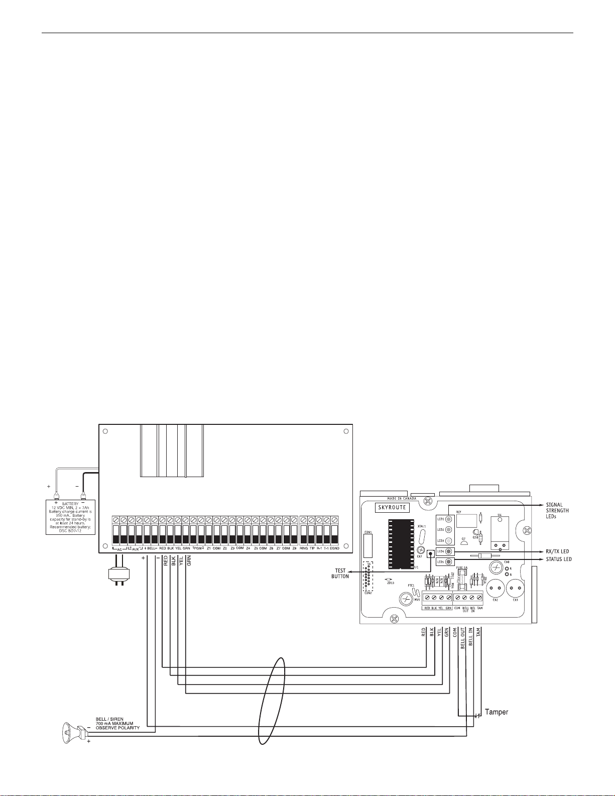
5.13 Connection Diagrams
Standard Connection with Compatible Control Panels (Non-Commercial Fire Applications)
DSC panel minimum
power requirements:
16 V
AC 40 VA transformer
12 V
RED BLK
CONTROL PANEL
WARNING
Remove all AC and battery
power from main control panel
before wiring the Skyroute
module, or damage to the
unit will occur.
DC 7 Ah battery
120V 60Hz
UL LISTED
Transformer
Bell Loop
700 mA Max.
UL Listed Class II
16.5 V @ 40 VA
Recommended:
DSC PTD1640U
Do not connect
transformer to receptacle
controlled by a switch. The
transformer must be UL
Listed and have a
restraining means.
Keybus to all modules
Refer to the Installation
Manual for detailed
information on wiring.
Be sure to observe polarity
when connecting polarized
sirens or bells
150' / 45.45 m max.
150' / 45.45 m max.
8

Standard Connection with PC5020CF / Partner P-8+CF (Commercial Fire Applications)
WARNING!
All connections to the Skyroute module are power limited. Do not route any wiring over the circuit
boards. Maintain at least 1” (25.4mm) separation between circuit board and wiring.
A minimum of 1/4” (7mm) separation must be maintained at all points between non power limited
wiring and power limited wiring.
Refer to your control panel Installation Manual for any additional information.
SO
SI
PC-Link Connection
RED BLK
PTC
AC
CONTROL PANEL
DC
Supervised
–
+
AUX
BLK YEL GRN Z1 Z3 Z5 Z7COM
REDBELL
–
+
1324
KEYBUS TO ALL MODULES
Refer to the Installation Manual for
detailed information on wiring.
COM
COM COMZ2 Z4 Z6 Z8 RING TIP R-1
EGNDPGM
T-1
NOTE: For commercial
Fire Applications DO NOT
connect any devices on
the "BELL+" terminal
(PC5020CF) other than the
Skyroute module.
Wiring Skyroute to a DSC PC5020CF/P-8+CF
place
Skyroute
.
Skyroute
Skyroute
Keybus
Skyroute
Skyroute
Skyroute
Skyroute
Skyroute
Skyroute
9
 Loading...