

Tyco Safety Canada 03RF5108 Users manual

RF5108-433 v1.0 Installation Manual
Thank you for purchasing the RF5108-433 Wireless Receiver. This product
is the result of several years of development and will allow you to connect
up to 8 wireless detection devices to the PC580, PC585, PC1555, PC1565, and the Power
Series control panels.
The RF5108-433 operates at 433 MHz. It provides several advantages:
• supervisory transmissions are sent every 64 minutes at fixed time intervals for NA
version, 12 minutes for the EU version.
• programmable supervisory window can be as long as 24 hours
• diversity antenna arrangement for better RF reception
• 2 PGM Outputs
In addition, the RF5108-433 features:
• 6 digit serial numbers for all wireless devices: These new serial numbers include
hexadecimal digits.
for more information on enrolling 6-digit devices.
We are confident you will find the RF5108-433 Wireless Receiver a unique and useful
control panel enhancement.
Section 1: Introduction
This manual describes how to install, program and maintain the RF5108-433.
Before you install the RF5108-433 module, you should have completed the following steps
in your system installation:
1. Plan the installation and wiring of the security system (see your system
Manual
)
2. Install the control panel, and install and enroll at least one keypad to use for
programming.
3. Install and enroll any hardwired zone expander modules (PC5108) you plan to use.
NOTE: PC5108 zone expander modules occupy zones in 2 groups of 4 (e.g. zones 9-12 and
zones 13-16). None of the zones assigned to a PC5108 module may be used for wireless
devices.
Program the RF5108-433 from a system keypad or using downloading software on a remote
computer (e.g., DLS 2002). Read your system
1.1 How to use this Manual
Read this manual before you begin installing the RF5108-433. To install and set up the
RF5108-433 and wireless devices, follow these steps. Refer to the sections listed below.
1. Temporarily mount and wire the RF5108-433 module (see
2. Enroll and program wireless devices (see
3. Complete zone and other programming on the system (see
4. Test the placement of all the wireless devices
5. Permanently mount the RF5108-433 receiver and wireless devices
For additional information on trouble conditions, RF jamming signal detection and battery
replacement, see
Please read Section 3.1 “A note on Electronic Serial Numbers (ESN)”
Installation
Section 6.
Installation Manual
Section 3
For help with troubleshooting, see
)
(see Section 5)
for more information.
Section 2
Section 4
)
)
(see Section 5)
Section 7.
WARNING: This manual contains information on limitations regarding
product use and function and information on the limitations as to liability of
the manufacturer.

I N T R O D U C T I O N
1.2 Specifications and Features
• Current Draw: 40mA
• Frequency: 433 MHz
• Zones - receiver can receive signals from up to 8 wireless zones and 8 wireless keys
• Internal antenna
• PGM Outputs: 2 Open-collector PGM outputs
• Supervisory - programmable supervisory window, 4 - 24 hours, in 15 minute increments
• Location
- can be wired up to 750 ft. / 230 m from the main panel with 22 gauge wire; the wiring
used in this circuit connection must be insulated with PVC, TFE, PTFE, FEP, Neoprene
or Polymide
- connects to Keybus
- for longer wire runs, thicker gauge wire must be used.
• Compatibility: The RF5108-433 v1.x can be connected to the following panels:
PC501X, PC1555, PC1565, PC580, PC585
PC5020,
1.3 Compatible Wireless Devices
Please refer to the Instruction sheets of the following devices for more information.
The RF5108-433 v1.0 can receive signals from the following devices:
• WLS904L-433 Motion Detector • WLS912L-433 Glass Break Detector
• WLS904PL-433 Pet Immune PIR • WLS914 Pet Immune PIR
• WLS906-433 Smoke Detector • WLS918-433 Panic Pendant
• WLS907-433 Universal Transmitter • WLS919-433 Wireless Key
• WLS907T-433 Low Temperature Sensor • WLS925L-433 Mini Door/Window Contact
• WLS909-433 Wireless Key
1.4 DLS Compatibility
The RF5108-433 can support up to 8 wireless devices that can be assigned to any of zones 1
to 32 or RF Jam Zone. If the DLS user enters valid serial numbers for more than 8 wireless devices
and the wireless device serial numbers are downloaded, the RF5108-433 will accept the serial
numbers of the first 8 wireless devices (in order, starting with the lowest zone number).
1.5 Batteries
The wireless devices are designed to use only specific brands and types of batteries.
Please see the appropriate instruction sheet for detailed information on the battery brands
and types.
NOTE: Do not use brands of batteries other than those specified. Using any other brand
may affect system operation.
Section 2: RF5108-433 Set up & Wiring
This section describes how to set up and wire the RF5108-433 module.
2.1 Unpack the RF5108-433
Check that the following parts are in your RF5108-433 package:
• 1 WLS919-433 wireless key
• RF5108-433 in cabinet
• Hardware for mounting the cabinet
• LED indicator plate
2

S E T U P & W I R I N G
2.2 Choose a Mounting Location for the RF5108-433
NOTE: Mount the RF5108-433 receiver and wireless devices after you have done placement tests with the wireless devices (see sections 5.1 and 5.2).
Find a place that is:
• Dry
• Central to the proposed placement of all wireless devices
• As high as possible
• Far from sources of interference, including: electrical noise such as computers, televisions
and electric motors in appliances and heating and air conditioning units; large metal
objects like heating ducts and plumbing which may shield the antenna.
Ensure the electrical wires will not run over the antenna(s) of the module when it is mounted.
NOTE: When mounting the RF5108-433 in a basement, place the module as high and as
close to the underside of the first floor as possible. The range of the module will be reduced if the unit is mounted below ground level.
2.3 Antennas
The antennas have been installed at the factory.
CAUTION!: Do not attempt to touch or adjust the antennas.
2.4 PC5320 Compatibility
The PC5320 module can be used to add multiple wireless receivers to an installation to
increase the coverage area. The PC5320 can be used to connect up to four wireless
receivers of the same type:
• up to four RF5108-433 receivers or
• up to four RF5501-433 receivers or
• up to four PC5132-433 receivers
Please refer to the PC5320 Installation Instructions for more information.
NOTE: If the PC5320 module is used, the RF5108-433 PGM outputs can only be programmed as RF5108 PGM Pulse or RF5108 PGM Toggle (Options 15 or 16).
2.5 Connect the RF5108-433 Receiver
CAUTION: Remove all power from the system while connecting modules to
the Keybus.
Connect the RF5108-433 to the 4-wire Keybus of the control panel according to the
following diagram.
Control Panel
KEYBUS
TO RF5108
3
S E T U P & W I R I N G
PGM1 GRNYELBLKREDPGM2
DSC
RM-1C
RED
BLK
WHT (COM)
YEL (NC)
GRN (NO)
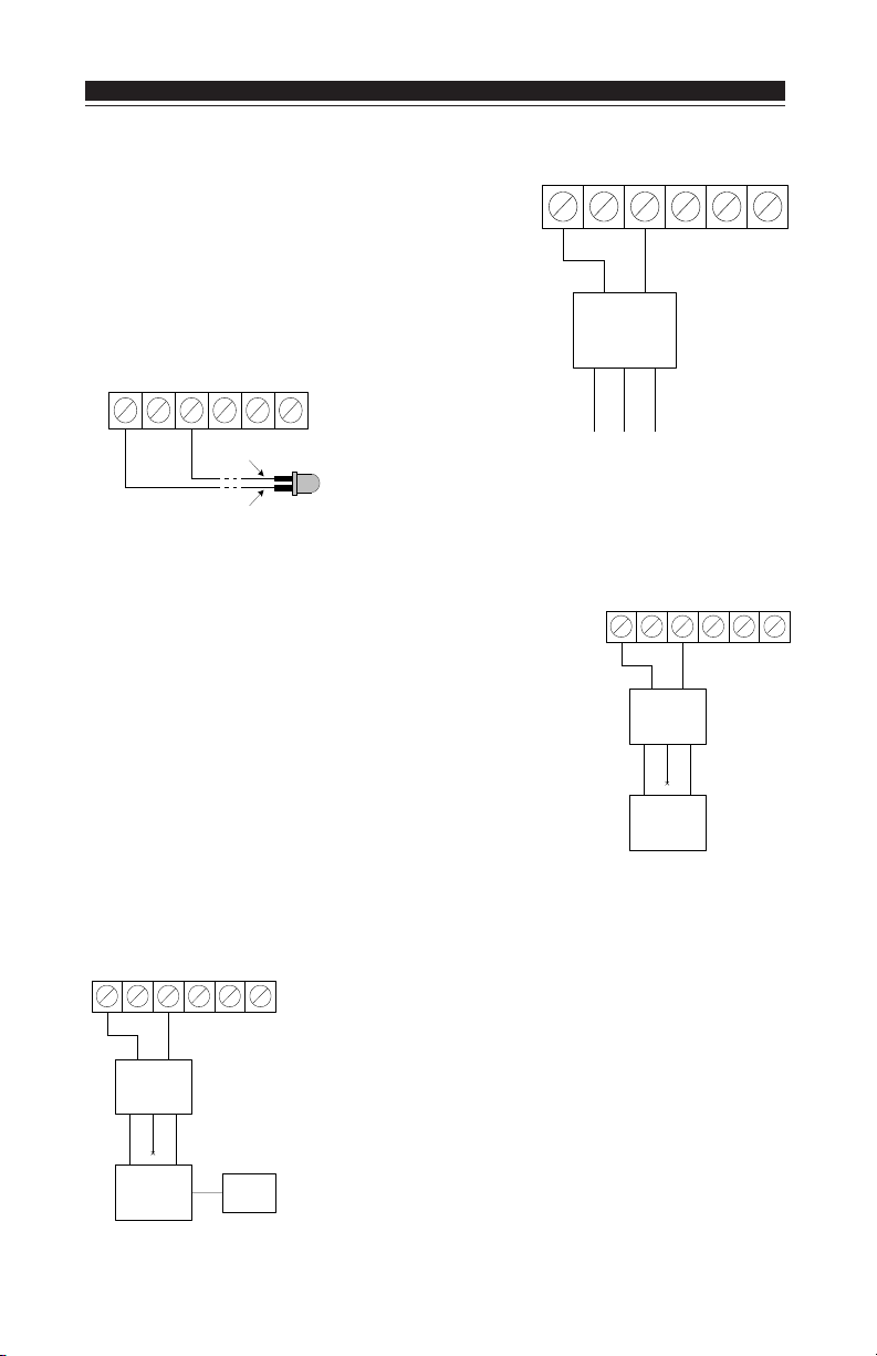
2.6 RF5108-433 Programmable Outputs - PGM1 and PGM2
Each PGM output is an open collector switch to ground.
That is, when the PGM output is activated the terminal
will switch to ground. PGM1 and PGM2 are able to sink
up to 300mA of current. If more than 300mA of current
is required a relay must be used. Refer to diagram
shown at right.
2.7 Connecting LED to the RF5108-433
PGM1 GRNYELBLKREDPGM2
RED
BLACK
The LED can be used
to indicate whether the
system is armed or disarmed. If the output is
programmed as an armed status output, the red LED will
turn on when the system is armed and will turn off when
the system is disarmed.
2.8 Connecting a Garage Door to the RF5108-433
Connect an output of the RF5108-433 across the wall-mounted
push button or directly at the motor of the garage door opener
(please consult the garage door opener instructions for proper
connections). Set up the system and wireless key so that it is
programmed to pulse an output for a short duration (5 seconds)
so that every time the programmed key is pressed the garage
door is opened or closed. The system can also be set up so that
an output on the RF5108-433 will follow a main panel output that
is programmed as a command output and is set up on the
wireless key as such. Doing this will also activate an output on
the RF5108-433 for 5 seconds (please refer to the control panel
manual for a listing of available output types and their functions). PGM 1 and/or PGM 2 on the RF5108-433 can be set up
to open a garage door (refer to Section 3.5).
PGM1 GRNYELBLKREDPGM2
WHT (COM)
Garage door
pushbutton
or motor
BLK
DSC
RM-1C
YEL (NC)
RED
GRN (NO)
2.9 Connecting an X-10 Powerflash Module to the RF5108-433
PGM1 GRNYELBLKREDPGM2
BLK
DSC
RM-1C
YEL (NC)
WHT (COM)
X-10
Powerflash
Module
RED
GRN (NO)
When connecting an X-10 Powerflash module to the RF5108433, different lights within or outside the home can be controlled, such as table lamps, or porch and driveway lights that
illuminate the entry / exit paths. This can be done by setting up
the system and wireless key in one of several ways:
• The wireless key can toggle an output ON/OFF, triggering the
X-10 Powerflash module, providing direct control of lighting.
• The wireless key can turn on an output for a programmable
amount of time (5 seconds to 99 minutes and 99 seconds),
Lamp
turning on lights for the amount of time the homeowner requires.
Module
4

S E T U P & W I R I N G
• The RF5108 output can be programmed to follow a main panel output which can turn on
lights when the panel is armed and turn them off when disarmed, turn on lights when an
alarm occurs and turn them off when disarmed, etc. Please refer to the control panel
Installation Manual for a listing of available output types and their function. PGM 1 and/
or PGM 2 on the RF5108-433 can be set up for this operation (see Section 3.5).
After you have completed the wiring, reconnect the power to the security system.
Now that you have wired the RF5108-433, you should enroll and program the wireless
devices. See section 3 for instructions.
Section 3: Enrolling Wireless Devices
This section describes how to enroll wireless devices and wireless keys. For more
information on these devices, read the instruction sheet included with each device.
3.1 A Note about Electronic Serial Numbers
An electronic serial number (ESN) is printed on the back of each wireless device. ESNs are
used to enroll the wireless devices with the RF5108-433 receiver.
In order to reduce the occurrence of wireless devices with the same serial number, 6-digit
serial numbers are now printed on the back of each wireless device. The 6-digit serial
numbers include hexadecimal digits. For instructions on programming hexadecimal
numbers, see your system
NOTE: 6-digit serial numbers are only supported on the following control panels: PC5020,
PC501X, PC1555, PC1565 and PC580, PC585 v2.0 and higher.
The WLS904L/904PL-433, WLS906-433, WLS907T-433, WLS912L-433, WLS914-433,
WLS918-43 and WLS925L-433 devices have both a 5-digit and a 6-digit serial number
printed on them. When connecting the RF5108-433 to a PC5010 v1.x panel, enter 5-digit
serial numbers only. When connecting the RF5108-433 to a PC5015 v2.x and higher,
PC5020, PC5010, PC1555/1565, or PC580/585 panel enter the 6-digit serial number.
3.2 Enrolling Wireless Devices
1. At a system keypad, enter [✱][8][Installer’s code] to go to the Installer Programming
section.
2. Enter programming section [804].
3. Enter the 2-digit number corresponding to the zone the device is to occupy ([01] to [32]).
NOTE: Hardwired and wireless devices cannot be assigned to the same zone. PC5108
zone expander modules occupy zones in 2 groups of 4 (e.g. zones 9-12 and zones 13-16).
None of the zones assigned to a PC5108 module may be used for wireless devices. For
more information on zone assignment, consult your system Installation Manual.
4. Enter the device’s ESN. Follow the instructions in section 3.1 above.
5. Record the serial number and the assigned zone number in the programming
worksheets in the back of this manual.
6. Repeat steps 3 - 5 until you have enrolled up to 8 wireless devices.
NOTE: The RF5108-433 supports programming of 8 wireless devices that can be assigned
to any of zones 1 to 32 or RF Jam Zone. Once 8 wireless devices have been programmed
the RF5108-433 will not allow further programming. An error tone will be heard at the
keypad if further programming is attempted
7. To exit press [#]. The device is now enrolled on the system.
NOTE: The devices will not work properly until you complete zone and partition programming (see section 4).
Installation Manual
, section 4: ‘How to Program’.
5

W I R E L E S S D E V I C E S
3.3 Enroll & Program Wireless Keys
For wireless keys to work on the system, you need to enroll them and then program the
function buttons. Wireless keys are not assigned to zones and require no zone programming. You can enroll up to 8 wireless keys on the system.
Enroll Wireless keys
1. At a system keypad, enter [✱][8][Installer’s code] to go to the Installer
Programming section.
2. Enter programming section [804].
3. Enter a 2-digit number [41]-[48] to assign the wireless key a slot. These numbers
correspond to wireless key numbers 01-08.
must
4. Enter the key’s ESN. The entry
is being enrolled, add the digit [0] to the beginning of the ESN. (E.g., if
ESN=61234, enter 061234)
5. The key is now enrolled on the system. Record the serial number and the assigned
slot number in the programming worksheets in the back of this manual.
6. Repeat steps 3 - 5 until all wireless keys have been enrolled.
((
PC5020/PC5020/
7.
(
PC5020/
((
PC5020/PC5020/
To assign keys to Partitions 2 to 8, program the appropriate partition number in
section [69].
PC501PC501
PC501
PC501PC501
XX
only) only)
X
only) By default, all wireless keys are assigned to Partition 1.
XX
only) only)
be 6 digits. If an older key with a 5-digit ESN
NOTE: A wireless key can only be assigned to one partition.
8. To exit press [#].
Program the Wireless Key Function Buttons
WLS909-433/WLS919-433 wireless keys have four programmable function buttons. By
default, all wireless key function buttons are set for 03, 04, 27, 30 (Stay Arm, Away Arm,
Disarm, Panic Alarm). The functions can be reprogrammed if desired. After the functions
are programmed, when you press and hold one of the buttons for two seconds, the system
will execute the programmed function.
For systems not using partitions: program the function buttons in section [61]. All
wireless keys will have the same four functions.
For systems using more than one partition (PC5020/PC501X only): All wireless keys
assigned to Partition 1 will have the four functions programmed in section [61]. Likewise, all
wireless keys assigned to Partition 2 will have the 4 functions programmed in section [62], and
all wireless keys assigned to Partition 8 will have the 4 functions programmed in section [68].
For example, if function button 1 in Section [61] is programmed for Stay arming, then pressing
the first button on wireless keys assigned to Partition 1 will Stay arm Partition 1.
NOTE: Wireless keys will not work when the partition they are assigned to is being accessed
for zone bypassing or programming.
1. At a system keypad, enter [✱][8][Installer’s code].
2. Enter programming section [804].
3. Enter programming section [61] to [68] for keys assigned to Partitions 1 to 8.
4. For each of the 4 function buttons, enter the 2-digit number of the function you
want to select. See the programming worksheets in the back of this manual for a
list of function key options.
5. Record your programming choices in the worksheets in the back of the manual.
6. To exit press [#].
6

W I R E L E S S D E V I C E S
3.4 Identified Wireless Keys
Reporting by the system of openings/closings by individual wireless keys and command
output [✱][7] activation by wireless key buttons may be supported on certain control panels.
To do this, the system will reserve access codes 17-24 for wireless keys 01-08 respectively.
You must program one access code for each wireless key (using [✱][5] access code
programming) for this feature to work correctly.
NOTE: Program these access codes on the system
after
you have connected the RF5108-
433 to the Keybus (see section 2.4).
Refer to your system
Installation Manual
for information on access code programming.
Opening/Closing By Wireless Key Reporting
NOTE: The Identified Wireless Key Closing option is only available with the PC5020,
PC501X, PC1555, PC1565, PC580, PC585 v2.0 and higher by turning section [015]
option 4 off.
To enable the reporting of openings and closings by identified wireless keys:
• Make sure the control panel is v2.0 or higher
• Program a valid access code for each key
• Program a closing and opening reporting code for each key’s access code
• Turn off the Quick Arm option in section [015] option [4] of the control panel programming
To ensure that an
option [1] (in the control panel programming). This option is available in control panels with
software version 2.1 or higher.
unidentified wireless key
cannot disarm the system, turn off section [017],
Command Output Activation
NOTE: The Identified Wireless Key Command Output Activation feature is only available
with the PC5020, PC501X, PC1555, PC1565, PC580, PC585 v2.0 and higher.
To enable command output activation by wireless keys, ensure that:
• The control panel is v2.0 or higher
• Program a valid access code for each key
• Enable the PGM output attribute Requires Access Code for each PGM output
programmed as [✱][7][1-4] in sections [141] to [154].
3.5 RF5108-433 PGM Outputs
The RF5108-433 has two on-board open collector PGM outputs. Each of these can be
individually programmed to:
1. Follow main panel PGM outputs 1 to 14.
NOTE: Please refer to your System Installation Manual for available PGM outputs.
NOTE: If the RF5108-433 is connected to the PC580/PC585/PC1555/PC1565/P-48/P-6B
(all versions), PC5010 v1.x, P832 v1.x or the WSS5010 1.0, 2.1, the RF5108-433 PGM
outputs cannot be programmed to follow main panel PGM outputs 1 or 2.
2. Activate for a programmable amount of time when a signal is received from a
wireless key programmed with output option 31 or 32 (RF5108-433 PGM pulse) and
the PGM output programming section [70] or [71] is programmed with option 15
(RF5108-433 PGM pulse). The amount of time that the PGM outputs can be
programmed to remain on is programmed in sections [72] and [73]. The default
activation time is 5 seconds.
3. Toggle state when a signal is received from a wireless key programmed with option
31 or 32 and the PGM output programming section [70] or [71] is programmed
with option 16 (RF5108-433 PGM toggle).
7

W I R E L E S S D E V I C E S
3.6 Deleting Wireless Devices
To remove a wireless device from the system, follow the guideline for adding a wireless
device. Program the ESN as [000000]. The wireless device for the zone will be removed.
Now that you have enrolled all the wireless devices, you will need to program the system
to work properly with the devices. See section 4 for more information.
Section 4: Other Programming
4.1 Program Zones and Partitions
Now that you have enrolled the wireless devices, you should complete all zone programming on the system. Although the exact programming required varies depending on which
control panel the RF5108-433 is connected to, you should check that the following
programming areas are completed correctly for each wireless zone:
• Enable zones and/or assign zones to one or more partitions (programming sections
[201]-[209], [201]-[265] for PC5020).
• Program the definition for each zone (programming sections [001]-[004]).
NOTE: WLS906 wireless smoke detectors must be assigned to zones defined as Delay
24-hr fire (wireless) [87] or Standard 24-hr fire (wireless) [88] for proper supervision.
• Enable the wireless zone attribute for each wireless zone (PC580, PC585, PC1555,
PC1565, PC5020, PC501X v2.0 and higher only) (sections [101]-[132]).
See your system
ming sections.
4.2 Enable RF5108-433 Supervision
The control panel will supervise the RF5108-433 receiver via the Keybus after at least one
device has been enrolled on the module (see section 3.2 “Enrolling Wireless Devices”). The
RF5108-433 is supervised as a PC5132.
To activate module supervision, after you enroll the first device(s):
1. Exit and then re-enter Installer Programming.
2. Enter programming section [902]. Wait approximately 1 minute.
3. To exit press [#].
The system will generate a General System Supervisory trouble if the module is removed
from the Keybus. If you need to remove the RF5108-433 module from an existing system,
you will have to disable supervision of the RF5108-433.
NOTE: Deleting all devices from the RF5108-433 or defaulting the RF5108-433 will cause
a PC5132 supervisory fault
Installation Manual
, for more information on each of the above program-
To disable RF5108-433 supervision:
1. Disconnect the RF5108-433 from the Keybus
2. Enter [✱][8][Installer’s Code]
3. Enter [902]. The control panel will clear all supervision and re-scan the system for
connected modules. The scan will take approximately one minute.
4. To exit press [#].
8
 Loading...