

Tyco Safety Canada 02WLS925LNB User Manual
WLS925L-433
Mini Door/Window Contact
Installation Instructions
Remove Cover
At the notched location on the cover, insert the flat blade of a small screwdriver
between the base and the cover and twist the screwdriver to pop the cover off.
Install Battery
Use care when installing the battery and observe the correct polarity (see diagram below). Use only the Eveready Lithium Energizer No. EL123AP, Tekcell
CR123A or Panasonic Lithium CR123A battery.
WARNING!: Battery may explode if mistreated. Do not recharge,
disassemble or dispose of in fire.
Locate Transmitter
Select the location where the transmitter is to be mounted. Perform the Module
Placement Test to ensure that the selected location is in range of the wireless
receiver (see receiver Installation Manual for instructions).
Remove Circuit Board
Before mounting the unit, remove the circuit board. At the notched location on
the base which is on the same side as the reed switch, insert the blade of a
small screwdriver between the base wall and the bottom of the circuit board
and pry the circuit board up.
NOTE: Do not touch the coils on the circuit board as this may damage the unit.
Mount Transmitter and Magnet
Mount the backplate of the transmitter using the screws provided and replace
the circuit board. The head of the screw must be below the circuit board so that
the sensor is not shorted out. Use flat-headed screws only.
Mount the magnet no more than ¼” from the transmitter. Use the spacers provided. Once the unit and magnet are mounted, open and close the window/
door to ensure that none of the parts interfere with this movement. Only one
magnet can be used per transmitter.
Using External Contacts
The external contact terminals can be used to connect external contacts or
other switches/devices to the universal transmitter. Install the additional device
as per the manufacturer’s instruction. Connect the device to the contact terminals of the WLS925L-433. The input is normally closed and is not supervised.
For UL installations, the wires connecting the external device to the input terminals must not exceed 36" (90.5 cm) in length. The contact and transmitter must
also be in the same room.
For non-UL installations, the wires connecting the external device to the input
terminals can be any length provided that the resistance of the wire does not
exceed 100 Ohms. Only one contact can be used. If an external contact is
used, do not install the magnet.
NOTE: When installing the WLS925L-433 with the use of the external
contact, ensure that the terminal block wiring is kept away from the
antenna.
WLS925L-433
Contact miniature pour Porte/Fenêtre
Instructions d’Installation
Enlevez le couvercle
Vis-à-vis l’encoche dans le couvercle, insérez la lame d’un petit tournevis plat entre
la base et le couvercle et tournez le tournevis de façon à faire ouvrir le couvercle.
Installez la pile
Installez minutieusement la pile en prenant soin de respecter la polarité (voir figure
ci-dessous). Utilisez seulement une pile de marque Eveready Lithium Energizer No.
EL123AP, Tekcell CR123A ou Panasonic Lithium CR123A.
AVERTISSEMENT!: La pile peut exploser si elle n’est pas utilisée correctement. Ne pas recharger, démonter ou jeter au feu.
Positionnez le transmetteur
Placez le transmetteur à l’endroit où vous souhaitez l’installer. Exécutez un Test
d’emplacement pour vous assurer que l’endroit choisi est à l’intérieur de la portée du
récepteur (pour plus de détails, référez-vous au manuel d’installation du récepteur).
Retirez le circuit
Avant de fixer l’unité, retirez le circuit électronique. Insérez la lame d’un petit
tournevis plat entre la base et le bas du circuit vis-à-vis l’encoche du côté du commutateur à lames. Ensuite, soulevez le circuit à l’aide du tournevis.
NOTE: Ne touchez pas aux selfs sur le circuit, cela pourrait endommager l’unité.
Fixez le transmetteur et l’aimant
Fixer la plaque arrière du transmetteur avec les vis fournies et replacez le circuit.
Pour éviter les courts-circuits, la tête des vis doit être plus basse que le circuit. Utilisez seulement des vis à tête plate.
Ne fixez pas l’aimant à plus de ¼” du transmetteur. Utilisez les separateurs fournis.
Une fois que l’unité et l’aimant sont installés, ouvrez et fermez la porte/fenêtre
pour vous assurer qu’aucune chose n’interfère avec le mouvement. Un seul aimant
peut être utilisé par transmetteur.
Usage d’un contact externe
Les bornes de contact externe peuvent être utilisées pour raccorder des contacts ou
d’autres dispositifs externes au transmetteur universel. Installez les dispositifs additionnels en suivant les instructions du fabricant. Raccordez le dispositif aux bornes
pour contact externe du WLS925L-433. L’entrée est normalement fermée et n’est
pas supervisée.
Pour les installations UL, la longueur du fil utilisé pour raccorder le dispositif
externe aux bornes d’entrée ne doit pas excéder 36" (90.5 cm). Le contact et le
transmetteur doivent également être dans la même pièce. Pour les installations qui
ne sont pas UL, le fil raccordant le dispositif aux bornes d’entrée peut être de
n’importe quelle longueur pourvu que la résistance du fil n’excède pas 100 Ohms.
Un seul contact peut être utilisé; si un contact externe est utilisé, n’installez pas
l’aimant du transmetteur.
NOTE: Lorsque vous utilisez le WLS925L-433 avec un contact externe,
assurez-vous d’installer le fil à l’écart de l’antenne.
WLS925L-433
Mini Contacto de Puerta/Ventana
Instrucciones de Instalación
Remover la Cubierta
En la ubicación dentada de la cubierta, inserte la cabeza plana de un destornillador
pequeño entre la base y la cubierta y mueva el destornillador para abrir la cubierta.
Instalarla Batería
Tenga cuidado cuando esté instalando la batería y observe la polaridad correcta (vea
el siguiente diagrama). Use solamente baterías Eveready de Litio Energizer No.
EL123AP, Tekcell CR123A o Panasonic Lithium CR123A.
ADVERTENCIA!: Las baterías puede explotar si son maltratada. No recargar, desmontar o botar en fuego.
Colocar Transmisor
Establezca el lugar donde el transmisor va a ser colocado. Efectúe la Prueba de ubicación del Módulo para asegurarse que la ubicación seleccionada está dentro del
alcance del receptor inalámbrico (consulte el Manual de Instalación del Receptor
para las instrucciones).
Remover el Tablilla del Circuito
Antes de montar la unidad, remueva el tablilla del circuito. En la ubicación dentada
de la base la cual está en el mismo lado como el interruptor de láminas, inserte la
cabeza de un destornillador pequeño entre el borde de la base y la parte inferior de
la tablilla del circuito y entremeta el tablero del circuito.
NOTA: No toque las bobinas de la tablilla del circuito ya que esto puede
dañar la unidad.
Montar el Transmisor e Imán
Monte la plaqueta posterior del transmisor usando los tornillos provistos y reinstale la
tablilla del circuito. La cabeza del tornillo debe estar por debajo del tablero del circuito
para que el sensor no sea corto circuitado. Use tornillos de cabeza plana solamente.
Monte el imán a no más de ¼” (6 mm) del el transmisor. Use los separadores provistos.
Una vez que la unidad e imán están montados, abra y cierre la ventana/puerta para
asegurarse que ninguna de las partes interfiere con este movimiento. Solo un imán por
transmisor puede ser usado.
Usar Contactos Externos
Las terminales du contacto externo pueden ser usadas para conectar contactos externos
o otros interruptores/dispositivos al transmisor universal. Instale el dispositivo adicional
de acuerdo a las instrucciones del fabricante. Conecte el dispositivo a las terminales del
contacto del WLS925L-433. La entrada es normalmente cerrada y no es supervisada.
Para instalaciones UL, los cables que conectan el dispositivo externo a las terminales
de entrada no deben exceder 36" (90.5cm) en longitud. El contacto y transmisor
deben estar en el mismo cuarto. Para instalaciones sin UL, los cables que conectan el
dispositivo externo a las terminales de entrada pueden ser de cualquier longitud
siempre que la resistencia del cable no exceda 100 Ohms. Solamente un contacto
puede ser usado. Si un contacto externo es usado, no instale el imán.
NOTE: Cuando instale el WLS925L-433 usando el contacto externo, mantenga el conjunto de terminales del cableado alejado de la antena.
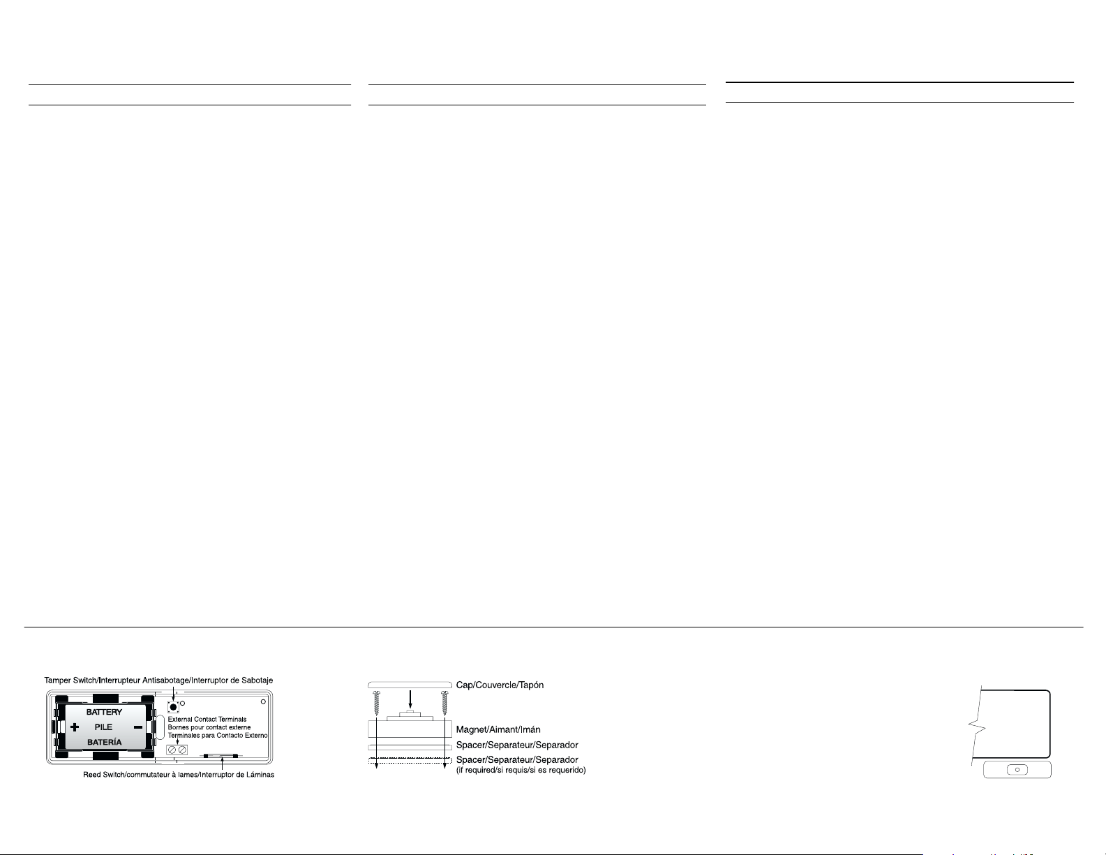
nstall Battery/Installez la pile/Instalarla Batería
Mount Transmitter and Magnet/Fixez le trans-
metteur et l’aimant /Montar el Transmisor e Imán
Locate Transmitter/Positionnez le transmetteur/Colocar el transmisor
Determine where the magnet will be placed. In order to activate the reed
switch, the magnet must line up with the end of the transmitter
Déterminez l’endroit où l’aimant sera installé. L’aimant doit être aligné
avec l’extrémité du transmetteur de façon à ce qu’il active le commutateur à lames.
Determine la posición donde el imán va a ser colocado. Para activar el
interruptor de láminas, el imán debe ser alineado con la parte al final del
transmisor.
Tamper Switch
There is one tamper switch on the WLS925L-433 board. Removing the cover will
cause a zone tamper.
Enrolling a WLS925L-433
On the back of the door contact housing, there will be two serial numbers, a five
digit and six digit. Please refer to your receiver Installation Manua l for information
on which serial number should be enrolled.
NOTE: Test unit at least once yearly. UL Listed for residential applications.
NOTE: Compatible with NT9010(A)-433, PC5132(A)-433, PC4164-433
and the LCD5501Z32-433.
Limited Warranty
Digital Security Contr ols Ltd. warrants that for a period of 12 months from the date of purchase, the
product shall be free of defects in materials and workmanship under normal use and that in fulfilment
of any breach of such warranty, Digital Security Controls Ltd. shall, at its option, repair or replace the
defective equipment u pon return of the equi pment to its repair depot. This warranty applies only to
defects in parts and workmanship and not to damage incurred in shipping or handling, or damage due
to causes beyond the control of Digital Security Controls Ltd. such as lightning, excessi ve voltage,
mechanical sho ck, water damage, or damage arising out of abuse, alteration or improper application
of the equipm ent.
The foreg oing warranty shall apply only to the o riginal buyer, and is an d shall be in lieu of any an d all
other warranties, whether expressed or implied and of all other obligations or liabilities on the part of
Digital Security Cont rols Ltd. Digital Securi ty Controls Ltd. neithe r assumes responsibility for, nor
authorizes any other person purporting to act on its behalf to modify or to change this warranty, nor to
assume for it any other warranty or liab ility concerning this product.
In no event shall Digital Security Controls Ltd. be liable for any direct, indirect or consequential damages, loss of anticipated profits, loss of time or any other losses incurred by the buyer in connection
with the purchase, installation or operation or failure of this product.
WARNING: Digital Sec urity Controls Ltd . recommends tha t the entire system be completely tested
on a regular basis. However, despite frequent testing, and due to, but not limited to, criminal tampering or electrical disruption, it is possible for this product to fail to perform as expected.
IMPORTANT INFORMATION: Changes or modifications not expressly approved by Digital Secu-
rity Controls Ltd. could void the user’s authori ty to operate thi s equipment.
FCC COMPLIANCE STATEMENT
CAUTION: Changes or mod ifications not expres sly approved by Digital Security Control s Ltd.
could void your a uthority t o use thi s equipment.
This equipment generates and uses radio frequency energy and if not installed and used properly, in
strict accordance with the manufacturer’s in structions, m ay cause interference to radio and television
reception. It has been type tested and found to comply with the limits for Class B device i n accordance
with the specifications in Subpart “B” of Part 15 of FCC Rules, which are designed to provide reasonable protection against such i nterference in any residential installation. However, there is no guarantee
that interference will not occur in a particular installation. If this equipment does cause interference to
television or radio reception, which can be determined by turning the equipment off and on, the user is
encouraged to try to correct the interference by one or more of the following measures:
•Re-orient t he receiving anten na
•Relocate the al arm control with respect to the receiver
•Move the al arm control away from the receive r
•Connect the alarm control int o a different outlet so that alarm contr ol and receiver are on different
circuits.
If necessary, the user should consult the deal er or an experienced radio/television technician for additional suggestions. The user may find the following booklet prepared by the FCC helpful: “How to
Identify and Resolve Radio/Television Interference Problems”. This booklet is available from the
U.S. Government Printing Office, Washington, D.C. 20402, Stock # 004-000-00345-4.
IC: 160A-W925LNB
The term ‘IC:’ before the radio certification number only si gnifies that Industry Canada technical
specifications were met.
Contact Antisabotage
Il y a un interrupteur antisabotage sur le circuit du WLS925L-433. Si le couvercle
est enlevé, une condition de sabotage de zone sera provoquée.
Assignation d’un WLS925L-433
Il y a deux numéros de série à l’arrière du boîtier, un de cinq chiffres et un de six
chiffres. Consultez le manuel d’installation de votre récepteur pour savoir lequel
doit être enregistré.
NOTE: Testez le dispositif au moins une fois par an. Homologué par UL
pour les applications résidentielles.
NOTE: Compatible avec le NT9010(A)-433, PC5132(A)-433, PC4164433 e LCD5501Z32-433.
Garantie limitée
Digital Security C ontrols Ltée., pen dant une période de douze mois à partir de la da te d’achat, garantit le produit contre toute défectuosité matérielle et d’assemblage dans des c ondi tions normales d’utilisation. Dans l’a pplication de ce tte garantie, Digital Security Controls Ltée. va, lorsqu’elle le juge
opportun, en cas de problèmes de fonctionnement, réparer ou remplacer les équipements défectueux
dès leur retour à son dépôt de réparation. Cette garantie s’applique seulement aux éléments défectueux et à la main-d’oeuvre, et non aux dommages causés lors de l’expédition ou de la manipulation, ni
aux dommages dont les causes dépassent le contrôle de Digital Security Controls Ltée. telles que la
foudre, les surtensions, les choc s mécaniques, le s dégâts d’eau ou tout dommage provenant d’abus,
de modifications ou de mauvaises utilisations de l’équipement.
La garantie susdite n’est valide que pour l’acheteur original et n’est et ne sera que la seul e des garanties
valables, qu’elle ait é té exprimée ou implicite, remplaçant toute autre obligation ou responsabilité d e la
part de Digit al Security C ontrols Ltée. La présente garantie contien t la garan tie au comple t. Digital
Security Controls Ltée. n’au torise aucune autre personne à agir en son nom pour modifi er ou changer
la présente garantie et n’en assume pas la responsabilité, ni a à assumer en son nom toute autre garantie
ou respon sabilité concernant le présent p roduit.
En aucun cas, Digital Security Controls Ltée . ne pourra être tenue responsable des conséquences
directes ou indirectes de dommages rel ativement à la perte de profits prévus, à la perte de temps ou à
toute autre perte subie par l’acheteur en rapport avec l’achat, l ’installation e t le f onctionnement ou l a
défaill ance du prés ent produit .
AVERTISSEMENT : Digital Security Controls Ltée. recommande que le système s oit régulièremen t
soumis à un essai complet. Cepen dant, en dépit d’essais réguliers et à cause d’interventions
criminelles, pannes de courant ou autres, il est possible que le fonctionnement du produit ne soit pas
conforme a ux spécifications .
INFORMATION IMPORTANTE : Tout changement ou modification qui n’est pas expressément
approuvé par Digital Security Controls Ltd. pourrait annuler le droit d’usage de cet équipement.
Interruptor de Sabotaje
Existe un interruptor de sabotaje en la tablilla WLS925L-433. Removiendo la cubierta causará un sabotaje de zona.
Registrar un WLS925L-433
En la parte posterior del empotramiento del contacto de puerta, habrán dos
números seriales, uno de cinco dígitos y el otro de seis dígitos. Por favor consulte el
manual de instalación de su receptor para obtener información acerca de cual
número serial debe ser registrado.
NOTE: Pruebe la unidad al menos una vez anualmente. Homologada
UL para aplicaciones residenciales.
NOTE:Compatible con el NT9010(A)-433, PC5132(A)-433, PC4164433 y LCD5501Z32-433.
Garantía Limitada
Digital Security Controls Ltd. garantiza que por un período de 1 año desde la fecha de adquisición, el
producto estará libre de defectos en material es y mano de obra baj o condi ciones de uso normal y que,
en cumplimiento de cual quier violación de dich a garantía, Digital Security Controls Ltd., p odrá, a su
opción, reparar o reemplazar el equipo def ectuoso a l recibo del equi po en su lo cal de servici o. Esta
garantía se aplica solamente a defectos en componentes y mano de obra y no a l os daños que puedan
haberse presentado durante el t ransporte y manipulación o a daños debidos a causas fuera del control
de Digital Security Controls Ltd. tales como rayos, voltaje excesivo, sacudidas m ecánicas, daños por
agua, o daños resultantes del abuso, alteraci ón o aplicación inadecuada del equi po.
La garantía anterior se a plicará solamente al comprador original y sustituye a cualquier otra gara ntía, ya
sea explícita o im plícita, y toda s las otras obligacio nes y responsabilidades por parte de Digital Secu rity
Controls Ltd. Esta gara ntía contiene la garantía total. Digital Security Con trols Ltd. no se comprome te,
ni autoriza a nin guna otra persona q ue pretenda ac tuar a su nombre, a m odificar o cambiar esta garantía
ni a asumir ni nguna otra garantía o responsabilidad con respecto a este producto.
En ningún caso, Digital Security Controls Ltd. será responsable de cualquier daño o perjuicio directo,
indirecto o consecuente, pérdid as de utilidades esperadas, pé rdidas de tiempo o cualquier otra pé rdida
incurrida por el c omprador con relaci ón a la adquisición, instalación, oper ación o fallo de este producto.
ADVERTENCIA: Digi tal Security Controls Ltd. recomienda que el sistema sea probado en su inte-
gridad con la debida regularidad. Sin embargo, a pesar de pruebas frecuentes y debido a interferencia
criminal o cortes eléctricos, pero no sólo limitado a ellos, es posible que este producto deje de operar
en la forma esperada.
INFORMACIÓN IMPORTANTE: Los cam bios o modif icaciones no aprobadas expresamente por
Digital Security Controls Ltd., pueden cancelar la autoridad del usuario para operar este equip o.
©2002 Digital Security Controls Ltd.
Toronto, Canada • www.dsc.com
Tech Line: 1-800-387-3630 (Canada & US)
Printed in Canada 29005998 R001
 Loading...