

Tyco Safety Canada 02WLS916NB User Manual
WLS916-433 Series
T
Wireless Smoke Detector
Installation and Operating Instructions
Read this instruction sheet thoroughly
before installation and use of the
WLS916-433 Wireless Smoke Detector
Introduction
The WLS916-433 is a wireless photoelectric smoke detector with a
fixed temperature heat detector and an internal piezoelectric
alarm. Three version are available: US version (UL), Canadian version (ULC) and an International version (EU).
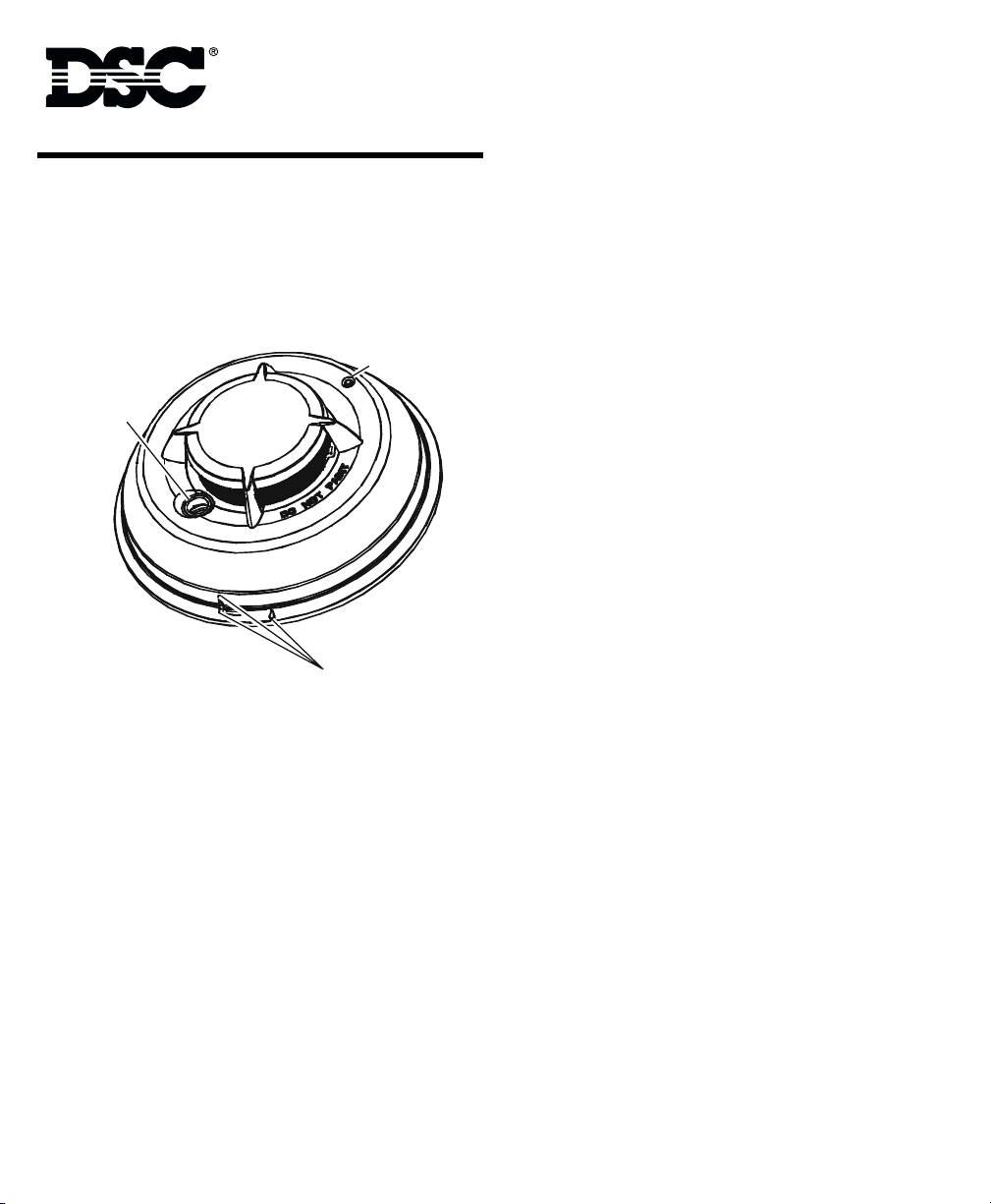
LED /Test Bu tto n
Piezo Sounder
Align ment Mark s
Operation
Approximately every 7 to 8 seconds the unit tests for a smoke or
heat alarm condition. During this sequence the unit also performs
self diagnostics, and checks for tampers and faults. During normal
operation the LED will flash every 48 seconds and the sounder will
not sound.
Smoke Alarm
The smoke detector has a nominal fixed alarm sensitivity of
approximately 2.5%/ft. obscuration. The smoke detector will go
into alarm when the signal level exceeds the 'alarm' threshold and
automatically restore when the signal level falls below the alarm
'restore' threshold. During an alarm the LED will flash 1/second
and the sounder will sound the the evacuation temporal pattern
(UL, EU) or continuous beeps (ULC).
The smoke detector has a preset warning threshold at 75% of the
alarm threshold. If the signal level stays above this threshold, but
below the alarm threshold, for more than 120 seconds, the detector will go into the 'warning' state. If the signal level falls below
the early warning 'restore' threshold, the detector will restore to its
normal state automatically. If the signal level rises above the alarm
threshold, the detector will go into alarm. The LED will flash and
the sounder will chirp every 48 seconds when in the warning state.
Note: This feature is intended to provide a warning if the environment is persistently close to the alarm threshold and provide more
time to investigate and either escape or correct the situation.
Smoke - Drift Compensation
The detector automatically compensates for long-term environmentally induced changes to maintain a constant smoke sensitivity.
When the drift compensation has reached its high or low limit of
adjustment, the detector will go into the trouble state.
Heat Alarm
The heat detector will go into alarm when the heat signal level
exceeds the heat alarm threshold (135ºF/57.22ºC); and will automatically restore when the heat signal level falls below the heat
alarm threshold (restore). During an alarm the LED will flash 1/second and the sounder will sound the the evacuation temporal pattern (UL, EU) or continuous beeps (ULC).
Batteries
The WLS916-433 is powered by two, 3 V
Do NOT use batteries other than those listed.
The low battery threshold is set so that the batteries will provide
not less than 14 days of operation and at that point the detector
will send a 'low battery' signal. If the battery is still low 7 days after
falling through the low battery threshold, the horn will 'chirp' once
every 48 seconds until battery failure. During the first 7 days after
low battery detection, (non-chirp period), if the detector is tested
or goes into alarm, the horn will 'chirp' once the test or alarm is
restored and remain 'chirping' until battery failure.
Tamper
The removal of the detector from the mounting plate initiates a
'tamper' transmission. The tamper condition is restored after the
detector is mounted on the plate.
Wireless Transmissions
A supervisory message is transmitted at 64 minute intervals (12
minutes in EU models) to the control panel. If the signal is not
received the control panel determines that the detector is missing.
The detector transmits the following:
• Alarm / Alarm Restore - (heat or smoke alarm). Transmitted
at time of occurrence.
• Tamper / Tamper Restore - (tamper switch activated) 10
second maximum delay on restore before transmission.
• Low Battery - (battery voltage falls below threshold). The
batteries are tested & transmitted at the time of a supervisory
or other transmissions.
• Trouble - (detector fault or sensor compensation limit
reached). Troubles are transmitted at the time of occurrence
(one trouble per supervisory interval).
DC lithium batteries.
F
A
R
D
Installation Instructions
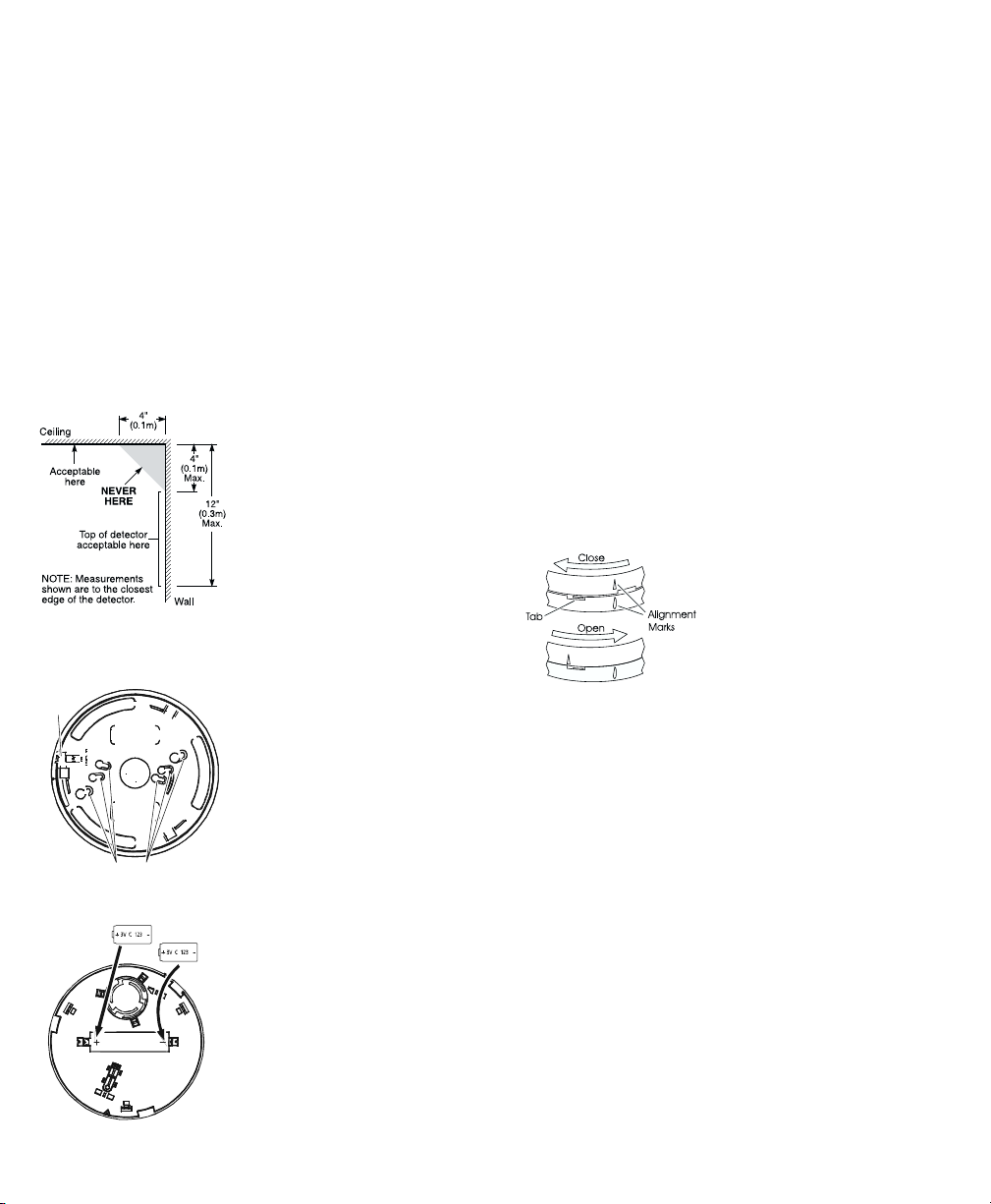
1 Smoke Detector Placement
On smooth ceilings, detectors may be spaced 9.1M (30 feet) apart
as a guide. Other spacing may be required depending on ceiling
height, air movement, the presence of joists, uninsulated ceilings,
etc. Consult National Fire Alarm Code NFPA 72, CAN/ULS-S553M86 or other appropriate national standards for installation recommendations.
Do NOT locate smoke detectors at the top of peaked or gabled
ceilings; the dead air space in these locations may prevent the unit
from detecting smoke.
Avoid areas with turbulent air flow, such as near doors, fans or
windows. Rapid air movement around the detector may prevent
smoke from entering the unit.
Do NOT locate detectors in areas of high humidity.
Do NOT locate detectors in areas where the temperature rises
above 38ºC (100ºF) or falls below 5ºC (41ºF).
Install Smoke detectors in accordance
with paragraph 2.1.1.1 of NFPA 72,
Chapter 2.
“2-2.1.1.1 Smoke detectors shall be
installed outside of each sleeping area in
the immediate vicinity of the bedrooms and
on each additional story of the family living
unit, including basements and excluding
crawl spaces and unfinished attics. In new
construction, a smoke detector also shall be
installed in each sleeping room.”
2 Mount Smoke Detector Backplate
Locking
Tab
Mounting Hol es
2 Install Batteries
Insert
Last
Secure backplate to the mounting
surface using the screws provided.
Note: Avoid mounting on uneven surfaces or electrical boxes. Warping of
the backplate can result in a tamper.
Install batteries in the sequence indicated. Use only 3 V
ies from the following approved
Insert
First
sources:
DC CR123A batter-
• Tekcell
• Ever Ready
• Panasonic
4 Test Unit
The test can be initiated by pressing the test button or activating
the internal reed switch with a magnet for a minimum of 5 seconds. Alarm activation will be indicated by the flashing LED, The
Sounder, and transmission of the alarm reporting code to the central station. The detector will restore to normal after the test button is released or the magnet removed.
Note: Allow a minimum of 20 seconds between test activations
Note: If the detector is in one of the following states when a test is
initiated; it will not enter an alarm state.
1. Tamper, (detector not installed on mounting plate).
2. Compensation Trouble.
3. Failure of Heat or Smoke detector.
4. Other internal faults that could prevent a smoke or heat alarm
Device Enrollment
The 6 digit serial number located on the back of the smoke detector housing must be enrolled into the alarm control panel with
Installer programming. Refer to the receiver Installation Manual
for details.
Mounting
Detector Installation:
Position the detector on to the base
plate using the detector and base
plate alignment marks. Press the
detector gently in place while rotating
the detector clockwise until the detector snaps into place. Remove the side
tab from the locking tab to lock in
place.
Removal:
Depress tab with a small slotted
screwdriver. Rotate detector counterclockwise until the alignment marks
line up. Remove detector.
Compensation Reset
Cleaning, replacement of the smoke sensor, or other environmental changes may change the background signal/noise of the detector; this requires the drift compensation be reset. Compensation
trouble is one of the faults indicated when the LED indicator is OFF
while the sounder is chirping.
1. Remove batteries
2. Power up unit while pressing the test button.
The tamper switch must not be pressed.
3. The LED will flash when 5 seconds has elapsed. Release the
test button within 2 seconds of the LED flash.
4. The LED will flash every 2 seconds for 1 minute. During this
period, the detector must be mounted.
Allow an additional 2 minutes for the detector to make
background level checks
5. Test the detector to verify normal operation.
 Loading...