

Tyco Safety Canada 01NB9010 Installation Guide

WARNING
This manual contains information on
limitations regarding product use and
function and information on the
limitations as to liability of the
manufacturer. The entire manual should
be carefully read.
NT9010
v 1.0
Installation
Guide
DLS-3 v1.3 and higher
™

Limited Warranty
Digital Security Controls Ltd. warrants the original purchaser that for a period of
twelve months fr om the date of purc hase, th e produc t shall be free of defects in
materials and workmanship under normal use. During the warranty period, Digital
Security Controls Ltd. shall, at its option, repair or replace any defective product
upon return of the product to its factory, at no charge for labour and materials. Any
replacement a nd/o r repai re d pa rt s are wa rran te d f or t he r em ain der of the o rigin al
warranty or ninety (90) days, whichever is longer. The original owner must
promptly noti fy Digital Se curity Con trols Ltd. i n writing tha t there is defect in
material or wor kma nshi p, s uch w ri tten no tice to be re ce ived in a ll events p ri or to
expiration of the warranty period.
International Warranty
The warranty fo r inte rnati onal c usto mers is the same as for any cust omer within
Canada and the U nited States , with the exce ption tha t Digital Sec urity Cont rols
Ltd. shall not be responsible for any customs fees, taxes, or VAT that may be due.
Warranty Procedure
To obtain service under this warranty, please return the item(s) in question to the
point of purch ase. All author ized distributors a nd dealers have a warr anty program. Anyone retu rn ing g oo ds t o D igit al Secu ri ty Co nt rols Lt d. m ust first obta in
an authorizat ion nu mber. Digi tal Se curit y Cont ro ls L td . wi ll n ot acc ep t any s hi pment whatsoever for which prior authorization has not been obtained.
Conditions to Void Warranty
This warranty applies only to defects in parts and workmanship relating to normal
use. It does not cover:
•damage incurred in shipping or handling;
•damage ca used by disa ster such as fire, floo d, wind, earthquake or lightning;
•damage due to cause s beyond th e cont rol of Dig ital S ecurity Contr ols Ltd. su ch
as excessive voltage, mechanical shoc k or water da mage;
•damage caused by unau thorized attachment, alteratio ns, modifications or foreign
objects;
•damage caused by peri ph eral s ( unle ss such pe riph er als w er e sup pl ied by D ig ital
Security Controls Ltd.);
•defects caused by failur e to provide a suitable insta llation environment fo r the
products;
•damage caused by use of the products for purposes other than those for which it
was design ed;
•damage fr om improper ma intenance;
•damage arising o ut of any other abuse, mishandlin g or imprope r applicatio n of
the product s.
Digital Security Controls Ltd.’s liability for failure to repair the product under this
warranty after a reasonable number of attempts will be limited to a replacement of
the product, as the exclusive rem edy for breach of warranty. Under no circum-
stances shall Digital Security Controls Ltd. be liable for any special, incidental, or
consequentia l dam ag es ba se d up on br each of warra nt y, breach of cont ra ct, negligence, strict liability, or any other legal th eory. Such damages include, but are not
limited to, loss of profits, loss of the product or any associated equipment, cost of
capital, cost of substitu te or repla cement equi pment, facil ities or se rvices, down
time, purchaser’s time, the claims of third parties, including customers, and injury
to property.
Disclaimer of Warranties
This warranty contains the entire warranty and shall be in lieu of any and all other
warranties, whet her expressed or implied ( including all implied warra nties of
merchantabil ity or fitness for a particular purpose) And of all other obligations or
liabilities on the part of Digita l Security Co ntrols Ltd. Di gital Securi ty Controls
Ltd. neither assumes nor authorizes any other person purporting to act on its
behalf to modi fy or to c hange thi s warrant y, nor to assume for it any other warranty or liability concerning this product.
This disclaimer of warranties and limited warranty are governed by the laws of the
province of Ontario, Canada.
WARNI NG: Digital Security Controls Ltd. recommends that the entire system be
completely test ed on a regular basis . However, despite frequent te sting, and due
to, but not limited to, criminal tampering or electrical disruption, it is possible for
this product to fail to perform as expected.
Installer’s Lockout
Any products return ed to DS C wh ich have the In st aller ’s Lockout opt ion en abl ed
and exhibit no other problems will be subject to a service charge.
Out of Warranty Repairs
Digital Secur ity Con trol s Ltd. will a t its option repa ir or r eplac e out-o f-war ranty
products which are retu rned to its fa ctory ac cording to the followin g conditio ns.
Anyone returning goods to Digital Security Controls Ltd. must first obtain an
authorization number. Digital Security Controls Ltd. will not accept any shipment
whatsoever for which prior authorization has not been obtained.
Products whic h Digital Secu rity Controls Ltd. determines to be repairab le will be
repaired and returned. A set fee which Digital Security Controls Ltd. has predetermined and whic h may be revised fr om time to time, will be charged f or each unit
repaired.
Products which Digital Security Controls Ltd. determines not to be repairable will
be replaced by the near est equivalent produc t available at that tim e. The current
market price of t he replacement prod uct will be charged f or each replacement
unit.
i

Table of Contents
Chapter 1: Quick Set Up
Section 1.1: Introduction
1.1.1 About the NT9010 System .................................1
1.1.2 About the NT9010 Manual Set .......................... 1
1.1.3 Main system Specifications .................................2
1.1.4 Additional Devices .............................................3
1.1.5 Peel-off Instruction Labels .................................. 4
Section 1.2: Installing The NT9010
1.2.1 Out of the Box ................................................... 5
1.2.2 Create an Installation Plan ..................................5
1.2.3 Prepare the Mounting Location .......................... 5
1.2.4 Installing the NT9010 ........................................5
1.2.5 Connecting the Battery ...................................... 6
1.2.6 Mounting the Wireless Devices ......................... 10
1.2.7 Enrolling Devices and Setting Up the System .... 10
1.2.8 Other NT9010 Options .....................................13
1.2.9 Deleting Wireless Devices .................................13
Section 1.3: Troubleshooting
1.3.1 Typical Installation Problems and Solutions ....... 14
Chapter 2: Advanced Programming
Section 2.1: Programming the NT9010
2.1.1 How to Enter Advanced Programming ............. 15
2.1.2 Programming Decimal Data ..............................15
2.1.3 Programming Hexadecimal Data ......................16
2.1.4 Programming Toggle Options ........................... 16
2.1.5 Programming Audio Labels ..............................16
2.1.6 Reviewing Programming .................................. 18
2.1.7 Exiting Programming ........................................18
Section 2.2: Changing How the NT9010
Works For Users
2.2.1 Accessing the NT9010 System Using a Telephone
19
2.2.2 Access Codes ...................................................20
2.2.3 Voice Prompt Interface ..................................... 22
2.2.4 Alarm Announce-ments ................................... 23
2.2.5 Arming and Disarming Options ........................ 24
2.2.6 Automatic Arming ...........................................25
2.2.7 Entry and Exit Delay Options ............................ 25
2.2.8 Bell Options .....................................................26
2.2.9 User Commands .............................................. 27
2.2.10Function Keys .................................................. 31
2.2.11Programming Wireless Keys ............................. 33
2.2.12 Fire, Auxiliary, and Panic Keys .......................... 33
2.2.13Keypad Options ............................................... 34
2.2.14Sleep Mode ..................................................... 35
Section 2.3: Changing Other NT9010 Functions
2.3.1 Zone Definitions .............................................. 36
2.3.2 Zone Attributes ................................................ 38
2.3.3 Enrolling Hardwired Zones ............................... 39
2.3.4 Wireless Device Serial Numbers ........................ 39
2.3.5 Wireless Zone Supervision ................................ 40
2.3.6 RF Jamming Detection Zone ............................. 40
2.3.7 Zone Tamper/Fault Options .............................. 41
2.3.8 Communicator Dialing ..................................... 41
2.3.9 Communicator Telephone Numbers ................. 43
2.3.10 Communicator Account Codes ........................ 44
2.3.11Communicator Reporting Formats ................... 44
2.3.12CommunicatorReporting Codes ....................... 47
2.3.13 Talk/Listen-in Programming .............................. 49
2.3.14Downloading ................................................... 51
2.3.15 Telephone Line Monitoring (TLM) .................... 53
2.3.16Test Transmissions ........................................... 53
2.3.17Event Buffer ..................................................... 54
2.3.18Swinger Shutdown .......................................... 54
2.3.19Timebase ......................................................... 54
2.3.20Factory Default ................................................ 54
2.3.21Installer Lockout .............................................. 55
2.3.22Walk Test ........................................................ 56
Appendix A: Guidelines for Locating Smoke
Detectors 57
Appendix B: Reporting Codes 58
Appendix C: WLS925L-433 Mini Door/
Window Contact Installation Instructions 61
Appendix D: WLS904P Wireless Motion
Detector Installation Instructions 62
ii

WARNING Please Read Carefully
Note to Installe rs
This warnin g contains vi tal informat ion. As the only indivi dual in conta ct with system users, it is your responsibility to bring each item in this warning to the attention
of the users o f this system .
System Failures
This system has been carefully designed to be as effective as possible. There are circumstances, however, involving fire, burgla ry, or othe r types of emergencies where
it may not provide protection. Any alarm system of any type may be compromised
deliberately or may fail to operate as expected for a variety of reasons. Some but not
all of these r easons may be :
Inadequate Installation
■
A security syst em must be i nstall ed proper ly in orde r to provid e adequate protec tion. Every installation should be evaluated by a security professional to ensure that
all access poi nts and ar eas are covered. Loc ks and latches on windows and doors
must be secure and op erate a s int en ded. Windows, do ors, walls , c eil ings an d ot he r
building materi als must be of sufficien t strength and construction to provide the
level of protection expected. A reevaluation must be done during and after any construction act ivity. An evaluation by t he fire an d/or po lice de pa rtme nt is h ighly r ec ommended if this service is available.
Criminal Knowledge
■
This system contains security features which were known to be effective at the time
of manufacture. It is possible for persons with criminal intent to develop techniques
which reduce the effectiveness of t hese f eat ures . It i s im port an t that a se curit y s ystem be reviewed peri odica ll y to en sure th at it s feat ure s re ma in effect ive and that it
be updated or re plac e d if it is fo und th at it doe s no t provide the pro tec ti on e xp ecte d.
Access by Intruders
■
Intruders may enter through an unprot ected access point, cir cumvent a sensing
device, evade detection by moving through an area of insufficient coverage, disconnect a warning d evice, or in ter fere wi th or pr event th e pro pe r ope ra tion of the s ys tem.
Power Failure
■
Control units, intrusion detectors, smoke detectors and many other security devices
require an adequ ate power supply fo r proper ope ration. If a devic e operates from
batteries, it is po ss ible for the ba tt erie s to fai l. E ven if the bat te ries have not fai led,
they must be charged , in good cond ition and in stalled corr ectly . If a dev ice operates
only by AC power, any interruption, however brief, will render that device inoperative while it does not have power. Power interruptions of a ny length are often
accompanied by voltage fluctuations which may damage electronic equipment such
as a security system. After a power interruption has occurred, immediately conduct
a complete sy stem test to e nsure that th e system oper ates as intend ed.
Failure of Replaceable Batteries
■
This system’s wirele ss t ra ns mitt ers h ave bee n desi gn ed to p rovide s everal yea rs of
battery life under normal conditions. The expected battery life is a function of the
device environment, usage and type. Ambient conditions such as high humidity,
high or low temperatures, or large temperature fluctuations may reduce the
expected battery life. While each transmitting device has a low battery monitor
which identifies when the batteries need to be replaced, this monitor may fail to
operate as expect ed. Regular testin g and maintenanc e will keep the system in good
operating condition.
Compromise of Radio Frequency (Wireless) Devices
■
Signals may no t reach the rec eiver under all circums tances which c ould include
metal objects placed on or near the radio path or deliberate jamming or other inadvertent ra dio signal in terference.
System Users
■
A user may not be able to operate a panic or emergency switch possibly due to permanent or tempor ary physical disa bility, inability to reach the device in time, or
unfamiliarity with the correct o peration. It is im portant that al l system users be
trained in the co rrect operation of the alarm system and that they know how to
respond when the system in dicates an al arm.
Smoke Detectors
■
Smoke detectors that are a part of this system may not properly alert occupants of a
fire for a number of reasons, some of which follow. The smoke detectors may have
been improp erly install ed or positi oned. Smoke may not be able to reach the smoke
detectors, such as when the fire is in a chimney, walls or ro ofs, or on the ot her side
of closed doors. Smoke detectors may not detect smoke from fires on another level
of the residence or building.
Every fire is different in th e amount of smoke pro duced and the ra te of burning.
Smoke detectors can not se ns e all ty pe s of fires eq ua lly we ll . Smo ke dete ct ors ma y
not provide timely warning of fires caused by carelessness or safety hazards such as
smoking in b ed, viol ent explos ions, es caping gas, im proper st orage o f flamma ble
materials, overloaded electrical circuits, children playing with matches or arson.
Even if the smoke d etector operates as intended, t here may be circ umstances when
there is insufficient warning to allow all oc cupants to esc ap e in time to avoid injury
or death.
Motion Detectors
■
Motion detectors can only detect motion within the designated areas as shown in
their respective ins tallati on ins tructi ons. Th ey cann ot discr imin ate be tween in trud ers and intended oc cupant s. Motion de tectors do not provide volu metric area protection. They have multiple beams of detection and motion can only be detected in
unobstructed areas covered by these beam s. They cannot detect m otion which
occurs behind walls, ceilin gs, floor, closed do ors, glass p artitions, gl ass doors o r
windows. Any type of tampering whether intentional or unintentional such as
masking, pain ting , or s pray ing of any m aterial on the le nses , mirr ors, windows o r
any other part of the detection system will impair its proper operation.
Passive infrared motion detectors operate by sensing changes in temperature. However their effectiveness can be red uced whe n the am bi ent te mp erat ur e rise s ne ar or
above body temperature or if there are intentional or unintentional sources of heat
in or near the detection area. Some of these heat sources could be heaters, radiators,
stoves, barbeques, fireplaces, sunlight, steam vents, lighting and so on.
Warning Devices
■
Warning devices such as sirens, bel ls, horns, or str obes may not warn peopl e or
waken someone sleeping if there is an intervening wall or door. If warning devices
are located on a di fferent level of the residen ce or premise, then it is less likely that
the occupants wil l b e ale rt ed or awaken ed. Audi bl e warn in g device s m ay b e i nter fered with by other nois e sour ces such as st er eos, radio s, tel evisi ons, air con di tion ers or other a ppli anc es, or p as sing tr affic. Aud ible war ning devic es, however loud,
may not be heard by a hearing-impaired person.
T elephone Lines
■
If telephone lines are used to transmit alarms, they may be out of service or busy for
certain period s of time. Also an intruder may cut the telephon e line or defeat it s
operation by more sophisticated means which may be difficult to detect.
Insufficient Time
■
There may be circumstances when the system will operate as intended, yet the
occupants will not be protected from the emergency due to their inability to respond
to the warnings in a timely manner. If the system is monitored, the response may
not occur in t i me to protect the occupan ts or their be longings.
Component Failure
■
Although every effort has been made to make this system as reliable as possible, the
system may f ail to functi on as intende d due to the f ailure of a component.
Inadequate Testing
■
Most problems that would prevent an alarm system from operating as intended can
be found by re gu la r tes ti ng an d ma inte na nce . The co mple te syst em shoul d b e test ed
weekly and imme diate ly after a br eak- in , an at temp te d brea k- in, a fire, a st or m, a n
earthquake, an accident, or any kind of construction activity inside or outside the
premises. The t esti ng shou ld inc lu de a ll sen sin g devic es , keyp ads, con so les, al ar m
indicating devices and any other operational devices that are part of the system.
Security and Insurance
■
Regardless of its capabilities, an alarm system is not a substitute for property or life
insurance. An alarm system also is not a substitute for property owners, renters, or
other occupa nts to ac t prude ntly to p revent or mi nimize t he harm ful effects of an
emergency situation.
iii

Chapter 1: Quick Set Up
Section 1.1: Introduction
1.1.1 About the
NT9010
System
1.1.2 About the
NT9010
Manual Set
The NT9010 is a full-featured, wireless security system. It has been designed for fast
and easy installation.
The NT9010 system is made up of the following components:
• A main control unit
• Up to 32 wireless detectors and panic pendants (total)
• You can also add up to 16 wireless keys.
The NT9010 system supports up to 32 zones (detectors and panic pendants), and
32 system users. The NT9010 main control unit guides users through their available
options with easy-to-understand audio prompts. The status of the NT9010 system
can be monitored over a telephone line.
You can program the system using the keypad on the NT9010 control unit, or using
DLS-3 downloading software and a computer. If you program the system from the
NT9010 control unit, you can do the basic zone enrollment and programming
using Flash Programming. See Chapter 1: Quick Set Up in the Installation Guide for
more information on using Flash Programming.
The NT9010 system has three manuals, Installation Guide, Programming Work-
sheets, and User’s guide.
☛ Installation Guide
The Installation Guide contains two main chapters.
Chapter 1: Quick Set Up
This chapter is for people who will be installing NT9010 systems requiring only
basic programming. This will be the case in the majority of installations. Please
review this chapter before beginning your installation. The Quick Set Up covers the
following topics:
• An overview of the system
• How to mount and complete NT9010 wiring
• How to enroll devices and program the system using Flash Programming
• Basic troubleshooting tips
• Guidelines for placing smoke detectors
Chapter 2: Advanced Programming
This chapter is for people who will be installing a system that needs special features
or custom programming. If your installation requires more programming than is
included in Flash Programming, review the relevant sections of this chapter for
more information.
1

Chapter 1: Quick Set Up
☛ Programming Worksheets
This manual is used to record your zone choices and other programming for the
system.
NOTE:
Keep this manual in a safe place for future reference.
☛ User’s Guide
The User’s Guide provides easy to follow instructions for NT9010 users. This Guide
contains instructions on turning the system on or off, dealing with alarms and
emergencies, using advanced functions, fire safety, and how to replace wireless
device batteries.
Installers should also review this manual, in order to properly instruct the end-users
once the installation is complete.
1.1.3 Main system
Specifications
Flexible Zone Configuration:
• 32 fully programmable zones
• 23 zone types, 8 programmable zone options
• Connect up to 2 hardwired zones
Access Codes:
• 38 access codes: 32 user codes, 1 Master code, 2 supervisor codes, 2 duress
codes, and 1 maintenance code
Remote Sounder Output:
• Four-wire supervised connection to optional remote sounder
• Can be wired up to 500ft (152m), 22AWG from the NT9010 control unit
• Capable of steady or pulsed siren, voice prompts, and central station talk/listenin sessions
EEPROM Memory:
• Will not lose programming or system status on complete AC and battery failure
Power Requirements:
• Plug-in transformer = 9V
AC, 20VA (use only DSC transformer PTD920)
• Battery = 6 volt 3.5 Ah rechargeable sealed lead acid (use only DSC battery
BD3.5-6V)
Digital Communicator Specifications:
• Supports all major formats including SIA, Contact ID, and 20bps formats
• Split reporting of selected transmissions to each telephone number
• 3 programmable telephone numbers
• 2 system account codes
• DTMF and pulse dialing
•DPDT line seizure
• Anti-jam detection
• Event-initiated personal paging
2

Section 1.1: Introduction
System Supervision Features
The NT9010 continuously monitors a number of possible trouble conditions including:
• AC power failure (system enters “Sleep” mode on loss of AC power for longer
than 30 seconds)
• Trouble by zone
• Fire trouble
• Telephone line trouble
• Low battery condition
• Remote sounder supervisory
• Loss of internal clock
• Tamper by zone
• Failure to communicate
• Improper zone placement
False Alarm Prevention Features
• Audible exit delay
• Audible exit fault
• Urgency on entry delay
•Quick exit
• Swinger shutdown
• Recent closing transmission
• Communication delay
• Rotating keypress buffer
Additional Features
• Keypad activated alarm output and communicator test
• Keypad lockout
• 128 event buffer, time and date stamped
• Uploading/downloading capability
1.1.4 Additional
Devices
WLS904-433 Wireless Motion Detector
The wireless motion detector can be used to provide wireless interior protection.
The unit comes with four AAA batteries.
WLS904P-433 Wireless Motion Detector with Pet Immunity
The wireless motion detector can be used to provide wireless interior protection.
The unit comes with four AAA batteries.
WLS906-433 Wireless Smoke Detector
The wireless smoke detector can be used to provide wireless smoke detection. The
unit comes with six AA batteries.
3
Chapter 1: Quick Set Up
WLS912-433 Wireless Glassbreak Detector
The wireless glassbreak detector can be used to provide wireless glassbreak detection. The unit comes with three AA batteries.
WLS914-433 Dual PIR Wireless Motion Detector
The dual PIR wireless motion detector can be used to provide wireless space protection. The unit comes with four AA batteries.
WLS925L-433 Mini Wireless Universal Transmitter
The WLS925L-433 wireless universal transmitter is a smaller transmitter that can be
used for door and window contacts. The unit comes with one Lithium battery and
has built-in contacts.
WLS929-433 Wireless Key
The wireless key can be used to provide a simple and mobile method of arming and
disarming the system. The unit comes with three Photo/Electronic 1.5V batteries.
This system can have a maximum of 16 Wireless Keys.
NT9201 Remote Sounder
You can connect a hardwired remote sounder to the NT9010 system. This sounder
provides an additional station for the NT9010 to sound alarms and system status,
and for central station talk/listen-in sessions.
NOTE:
Maximum distance for the Remote Sounder is 500ft (152m) using
22AWG sheilded cable.
1.1.5 Peel-off
Instruction
Labels
4
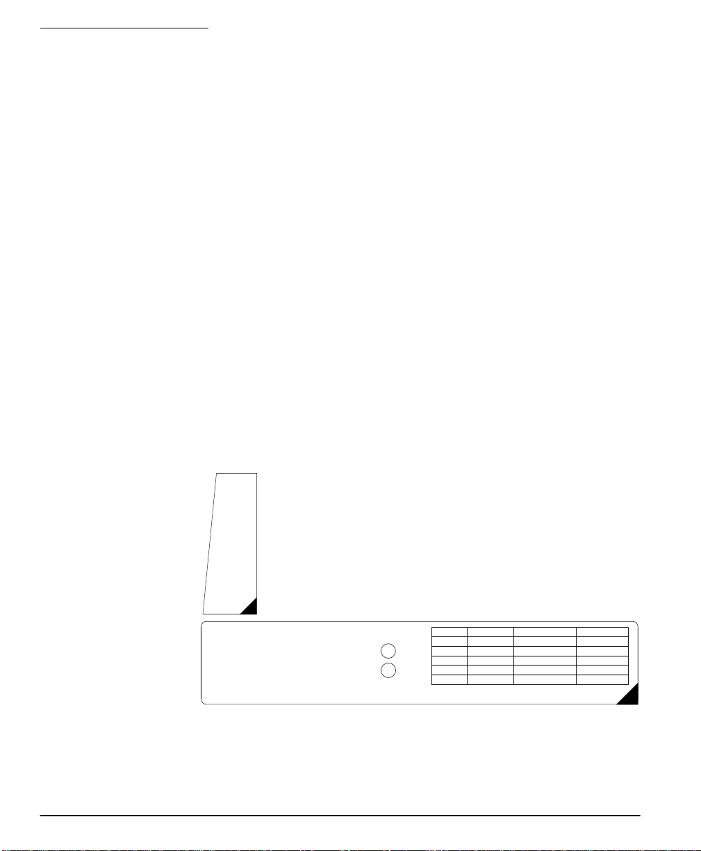
The Envoy unit comes with a set of peel-off instruction labels already applied.
Installer should remove these labels after installation. For future programming
needs, please see sample labels below for instructions.
A
B
C
D
E
F
Back
Forward
The NT9010's "Flash" programming will help you to quickly set up the system.
To begin:
1. Press [ ][8]
2. Enter the default installer’s code: [5555]
3. Follow the audio instruction
For contacts used on the hardwired zones:
!
!
Use
PEEL
OFF
✱
Enter serial number 200001 for the first hardwired zone
Enter serial number 200002 for the second hardwired zone.
buttons [A] to [F] for entering letters in serial numbers.
A = Stay
B = Away
C = Chime
D = Exit
E = Status
F = Volume
Back = Record
Forward = Playback
=YES
1
= NO
2
Selection Type 2 (TX) Type 3 (PIR) Type 4 (Smoke)
[A] Preset Front Door Main Floor Motion Main Floor Fire
[B] Preset Back Door Upstairs Motion Upstairs Fire
[C] Preset Garage Door Downstairs Motion Downstairs Fire
[D] Preset Window Hallway Motion Hallway Fire
[E] Preset Patio Door Garage Motion Garage Fire
Please use
buttons [A] to [E] for standard label options
ALSO REFER TO INSTALLATION MANUAL
PEEL
OFF

Section 1.2: Installing The NT9010
Please read this section to get an overall understanding of the steps involved in
installing the NT9010 system. Carefully work through each step. This will help to
reduce problems and to reduce the overall installation time required.
1.2.1 Out of the
Box
1.2.2 Create an
Installation
Plan
Check that the following parts are included in your NT9010 package:
• NT9010 main control unit and backup battery
• Two WLS925L-433 transmitters
• One WLS904P-433 motion detector with pet immunity
• One 9V, 20VA plug-in transformer
• One set of Installation, Programming Worksheets and User manuals
• Two 5600Ω resistors
• 4 mounting screws
Draw a rough sketch of the building. Find good locations for the NT9010 control
unit and all the detectors. Here are some guidelines for choosing good mounting
locations.
Choosing a NT9010 Mounting Location
Before you mount the NT9010, you should find a place that is:
•Dry
• Far from sources of interference, including:
■
electrical noise such as computers, televisions and electric motors in appliances and heating and air conditioning units.
■
large metal objects like heating ducts and plumbing which may shield the
antenna.
Choosing Mounting Locations for Wireless Devices
Each type of wireless device has its own set of guidelines for mounting locations.
Before deciding on mounting locations, make sure that you review the guidelines in
the Installation Instructions that come with each device.
1.2.3 Prepare the
Mounting
Location
1.2.4 Installing the
NT9010
Once you have selected a suitable place for the NT9010 control unit, make sure
that you will be able to connect the AC power and the telephone line to the
NT9010. If necessary, have an electrician route AC wiring to the mounting location,
and have a telephone installer route the incoming telephone line to the mounting
location.
Mounting the NT9010 Backplate
The NT9010 backplate is the blue-grey piece of plastic that comes attached to the
back of the NT9010 control unit. This is the mounting plate for the NT9010 unit. It
also provides terminals for connecting the wiring to the NT9010.
5
Chapter 1: Quick Set Up
NOTE:
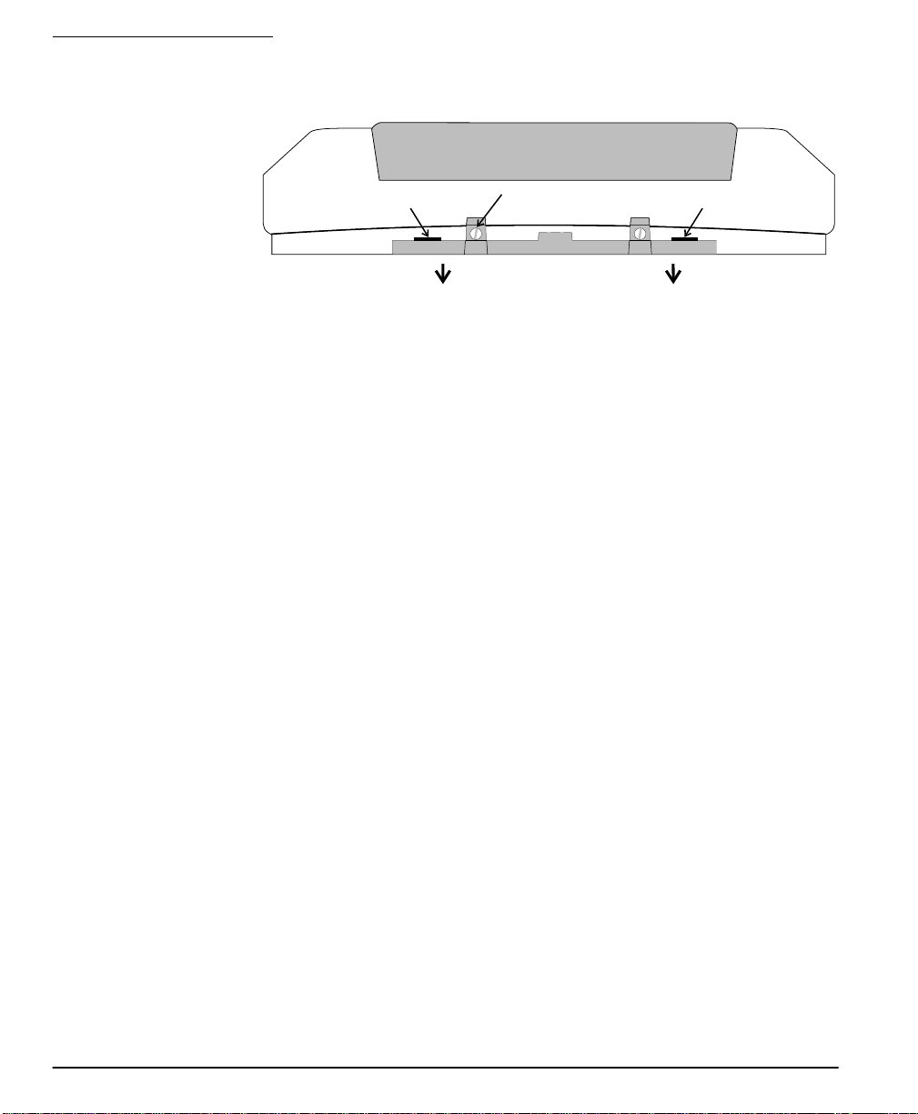
Figure 1: Removing NT9010 Wall-Mount Backplate
Complete all wiring before applying AC power.
1. Remove
2. Twist with
Screwdriver
plastic screw
3. Pull top of backplate
away from NT9010
2. Twist with
Screwdriver
To remove the backplate from the NT9010:
1. Remove the plastic screw from the top of the NT9010 unit (see Figure 1). Keep
the screw in a safe location so that you can replace it later.
2. Insert a flathead screwdriver in the slots shown in Figure 1. Twist the screwdriver
so that the backplate separates from the plastic housing.
3. Pull the top of the backplate away from the NT9010.
4. Unhook the backplate from the bottom of the NT9010.
Now you can attach the backplate to the wall:
1. Pull the prepared AC and telephone wires through the square hole in the backplate.
2. Place the backplate on the wall in the selected mounting location, and mark the
screw locations.
3. Using wall anchors for all screw locations, secure the backplate to the wall.
1.2.5 Connecting
the Battery
6
Before you attach the NT9010 to the backplate, you must connect the battery. The
battery is used to provide backup power in the event of an AC power failure and to
provide additional current when necessary, such as when the system is in alarm.
NOTE:
Place the unit face down before removing the plastic.
1. Remove the two metal screws at the back of the NT9010.
2. Remove the back plastic from the NT9010.
3. Connect the RED battery lead to the positive (+) terminal of the battery, the
BLACK battery lead to the negative (-) terminal.
4. Replace the back plastic on the NT9010 and secure it with the metal screws.
NOTE:
The unit will not power up if only the battery is connected. AC
power must also be connected to the NT9010.
Section 1.2: Installing The NT9010
Connecting AC and Telephone Wiring
Connect the AC and telephone line wiring to
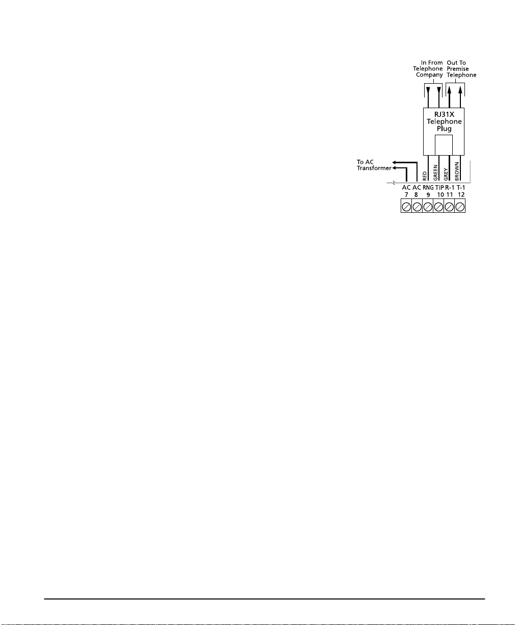
Figure 2: AC and Telephone Line Wiring
the terminals mounted on the NT9010 backplate. When you later attach the NT9010 to
the backplate, the posts on the back of the
unit will plug into the terminals, completing
the connection.
AC Terminals
For the NT9010 to work correctly, you will
need to connect it to an AC power source that
is not controlled by a switch. The system
comes with a 9V, 20VA plug-in transformer.
Connect the transformer to an unswitched AC
source and to the two terminals on the backplate labelled AC.
NOTE:
Risk of fire if the rated voltage is not used. Do not power the
Envoy controller at a voltage higher than 9V AC. Use only transformer
Model PTD920 as supplied with the unit.
NOTE:
Do not connect the transformer to a power supply until all other
wiring is complete.
NOTE:
If you remove power from the unit (AC and battery), you must
wait at least 10 seconds before reapplying power.
Telephone Terminals - TIP, RING, T-1, R-1
If a telephone line is required for users to have local or remote telephone access to the
system, for central station communication, or for downloading, connect an RJ-31X
jack to the R-1, T-1, RING, and TIP terminals on the backplate as shown in Figure 2.
NOTE:
Please ensure that all plugs and jacks meet the dimension, tolerance and metallic plating requirements of the Code of Federal Regulations,
Title 47, Part 68, Subpart F. For proper operation there must be no other
telephone equipment connected between the control panel and the telephone company facilities.
Do not connect the alarm panel communicator to telephone lines intended
for use with a FAX machine. These lines may incorporate a voice filter which
disconnects the line if anything other than FAX signals are detected, resulting in incomplete transmissions.
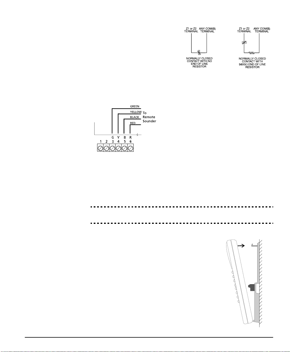
Connecting Zone Wiring – Hardwired
You can connect up to two hardwired zones to the NT9010. For the hardwired
zones to work correctly, you must enroll them with the system (see 2.3.3 Enrolling
Hardwired Zones on page 39). For a complete description of the operation of all
zone types, please see 2.3.1 Zone Definitions on page 36.
7
Chapter 1: Quick Set Up
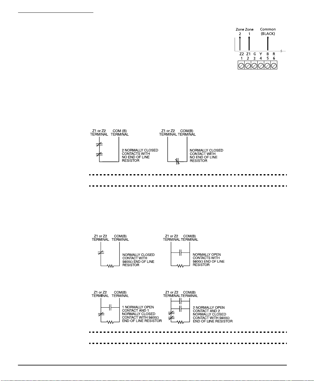
Use the following NT9010 terminals to make your zone
connections:
There are two different ways in which zones may be wired,
depending on which programming options have been
selected. The system can be programmed to supervise normally closed, or Single End of Line loops. Please refer to the
following sections to study each type of individually supervised zone wiring.
Normally Closed (NC) Loops
To enable normally closed loops, programming section [013], option [1] must be
ON.
NOTE:
This option should only be selected if Normally Closed (NC)
devices/contacts are being used.
Normally Closed Loops . . . . . . . . . . . . . . . . . . . . . . . . . . Section [013], Option [1]
Single End Of Line (EOL) Resistors
To enable system detection of single end of line resistors, programming section
[013], option [1] must be OFF.
NOTE:
This option should be selected if either Normally Closed (NC) or
Normally Open (NO) detection devices or contacts are being used.
End of Line Resistors . . . . . . . . . . . . . . . . . . . . . . . . . . . . Section [013], Option [1]
8
Section 1.2: Installing The NT9010
Keyswitch Zone Wiring
Zones may be programmed to be used as
keyswitch arming zones and must be
wired according to the following diagram:
For a complete description of how keyswitch zones operate, see 2.3.1 Zone
Definitions on page 36.
Connecting the Remote Sounder
You can connect a hardwired remote sounder to the NT9010 system. This sounder
provides an additional station for the NT9010 to sound alarms and system status,
and for central station talk/listen-in sessions.
Connect the remote sounder to the NT9010 control unit as shown below:
For the sounder to work on the system you must
also turn on the Remote Annunciation option.
When this option is turned on, the remote
sounder will also be supervised.
The Local Annunciation option controls the
sounder in the NT9010 control unit. If you turn
this option off, there will be no alarms or voice
prompts from the NT9010. If both options are on, there will be sound from both
the NT9010 and the Remote Sounder.
If there is a Remote Sounder on the system and it does not report a supervisory signal within 30 seconds, a “Service Required” trouble will be generated, and a
“Remote Sounder Trouble” event will be logged in the buffer.
See also 2.3.13 Talk/Listen-in Programming on page 49.
Local Annunciation . . . . . . . . . . . . . . . . . . . . . . . . . . . . . Section [017], Option [4]
Remote Annunciation . . . . . . . . . . . . . . . . . . . . . . . . . . . Section [017], Option [5]
Attach NT9010 to Backplate
NOTE:
Before attaching the backplate, be
2. Snap top of
NT9010 onto
top of backplate
sure to connect the battery. See 1.2.5 Connecting
the Battery on page 6.
When you have mounted the backplate to the wall,
completed the wiring, and connected the battery, you
WALL
can attach the NT9010 unit to the backplate.
1. Push the bottom of the NT9010 onto the backplate posts, as shown at right.
2. Snap the top of the NT9010 onto the top of the
backplate, as shown at right.
3. Secure the NT9010 to the backplate by replacing
the plastic screw in the top of the NT9010.
1. Push bottom
of NT9010 onto
backplate posts
9

Chapter 1: Quick Set Up
1.2.6 Mounting
the Wireless
Devices
1.2.7 Enrolling
Devices and
Setting Up
the System
Do not permanently mount the wireless devices until you have completed the
Placement Tests (see 1.2.7 Enrolling Devices and Setting Up the System on
page 10). Once you have a good location for each of the devices, follow the
mounting instructions on the Installation Instruction sheet for each device. For
WLS904P-433, see Appendix D: WLS904P Wireless Motion Detector Installa-
tion Instructions on page 62. For WLS925L-433, see Appendix C: WLS925L-433
Mini Door/Window Contact Installation Instructions on page 61.
Flash Programming will guide you through the steps needed to set up each zone and
basic system programming. If you need to perform more advanced programming for
your installation, please see Chapter 2: Advanced Programming on page 15.
To access Flash Programming:
1. Press [✱][8].
2. Enter the Installer’s code. The Installer Code is [5555] at default, but should be
changed to prevent unauthorized access to programming.
3. Press [1] to enter Flash Programming.
4. Follow the audio instructions announced by Flash Programming. Flash Programming will guide you through the following programming areas:
■
Device enrollment
■
Zone label assignment
■
Central station telephone number
■
System account code
■
Placement tests of each wireless device
You can use the Forward (Playback) button to advance to the next section in
Flash Programming, and the Backward (Record) button to return to the previous
section.
5. Be sure to record all the zone serial numbers and your programming choices in
the NT9010 Programming Worksheets.
Here are some notes about system programming done through Flash Programming.
10
Zone Definitions
When you enter a serial number for a device into the NT9010 Flash Programming,
the unit will analyze the number to determine what kind of device you are enrolling. Based on the type of device, the system will make the following programming
choices:
Device Type Zone Definition Other Programming
Door/window contact
(2XXXXX, including hardwired contacts entered as
200001 and 200002)
Motion or glassbreak
detector (3XXXXX)
Smoke detector
(4XXXXX)
Delay 1 (Type [01]) For hardwired zones (serial
numbers 200001 and
200002), Zone Supervision
disabled (section [804])
Interior Stay/Away
None
(Type [05])
Delayed 24 Hour Fire
None
(Type [87])
Wireless key (6XXXXX) None None

Section 1.2: Installing The NT9010
NOTE:
entry/exit point zones first.
NOTE:
To ensure that the NT9010 works properly, you should enroll all
PIR’s covering entry points should be zone type [06] Delay Stay/Away
[01] Delay 1 Zone: If this zone is violated when the system is armed (e.g.
door or window is opened), the entry delay will begin. The buzzer
will sound to warn the user that the system must be disarmed. If the
system is not disarmed before the entry delay expires, an alarm will
be generated.
[05] Interior Stay/Away Zone: If this type of zone is violated when the
system is armed (e.g. the motion detector senses motion), an instant
alarm will be generated unless a Delay Zone is violated first. If a Delay
Zone is violated first, this zone will also follow the entry delay.
The zone will be automatically bypassed under the following conditions:
■
the NT9010 is armed in the Stay Mode
■
the NT9010 is armed without entry delay ([✱][9] arming)
■
the NT9010 is armed with an access code and during the exit delay a
Delay zone is NOT violated (user does not go through the entry/exit
door).
If zones are automatically bypassed, the user can reactivate the zones
by entering [
✱
][1].
[87] Delayed 24 Hour Fire (Wireless): If this zone is violated (e.g. the
smoke detector senses smoke), the alarm will immediately sound,
but the alarm communication to the central station will be delayed
for 30 seconds. If during the 30 second delay the user presses the [#]
key, the alarm and communicator will be delayed an additional 90
seconds. This provides time for a user to correct the problem.
If after the 90 second delay the zone is still violated the process will
begin again: the alarm will sound but the alarm communication will
be delayed for 30 seconds.
If the user does not press the [#] key, after 30 seconds the alarm will
latch on and the system will communicate a fire alarm to the central
station. The alarm will sound until the Bell Cutoff time expires, or
until a valid code is entered.
11

Chapter 1: Quick Set Up
Programming Zone Labels
If an enrolled device is a door/window contact, motion detector, glassbreak detector, or smoke detector the system will then prompt you to enter an audio label for
the new zone. You can choose from any of the following preset audio labels:
Press
Function
Key:
Door/window
contacts
(2XXXXX)
Motion or
glassbreak
detector
(3XXXXX)
Smoke detector
(4XXXXX)
A Front door Main floor motion Main floor fire
B Back door Upstairs motion Upstairs fire
C Garage door Downstairs motion Downstairs fire
D Window Hallway motion Hallway fire
E Patio door Garage motion Garage fire
If necessary, you can also program custom labels for the zones through the NT9010
Flash Programming.
1. For door/window contacts, motion detectors, and glassbreak detectors, at the
appropriate place in Flash Programming, instead of selecting labels A to E, press
function key F.
2. You can now enter up to six pre-programmed words from the Audio Label
Library. For each word you want to program, enter a 3-digit code from the Label
Library (for a list of labels and codes, see the NT9010 Programming Worksheets,
Appendix A). If your label is less than six words, press [#] at the end of the label.
3. If you want to use a recorded label instead of the words available in the Audio
Label Library, enter [244] for the first label entry, then the number of the label
[001] to [005]. The recorded label will replace all six words in the section. You
will not be able to add additional words to the label. To record a label for a
zone, please see section 2.1.5 Programming Audio Labels on page 16.
4. When you have entered the label, the system will recite it. If the label is correct,
press [1]. If the label is not correct, press [2] and repeat steps 1 to 3 to fix the label.
NOTE:
You must accept a label to exit this section. If you choose F for a
custom label, then you must create your own label using the Audio Label
Library and accept it.
NOTE:
If you chose one of the audio labels, section [001] to [005] (#3
above) and there is no audio label recorded, the label will default to “zone
X” where “X” is the zone number of the device enrolled. When the label is
recorded in section [807], [701] to [705] it will be used.
12
Entering the Central Station Telephone Number
When prompted, enter the telephone number for the central station. The number
can be up to 32 digits long. When you program the number, the system automatically inserts the hexadecimal digit “D” at the beginning, to tell the system to con-

Section 1.2: Installing The NT9010
duct a dial tone search before dialing. If necessary, you can enter the following
hexadecimal digits in the telephone number:
• HEX B to dial “✱” (function button B “Away”)
• HEX C to dial “#” (function button C “Chime”)
• HEX D for an additional dial tone search (function button D “Exit”)
• HEX E to insert a 2-second pause (function button E “Status”)
When you have finished entering the telephone number, press [✱]. The system will
recite the number back to you.
Entering the Account Code
The system will send the account code to the central station when communicating
system events (e.g. Low Battery, Test Transmission). Enter a 4-digit code.
Testing the Placement of Wireless Devices
Each wireless detector must pass three consecutive placement tests before it will
work properly on the system. Follow the instructions in Flash Programming to conduct the tests. The buzzer will squawk once for “Good” placement and three times
for “Bad” placement.
If you exit the Placement Test section before all the zones have passed the necessary placement tests, a General System Trouble is generated. This trouble can only
be cleared by re-entering the Placement Test and testing all of the devices that have
not yet passed, or by deleting the serial numbers of the devices that did not pass
the test (see 1.2.9 Deleting Wireless Devices on page 13).
NOTE:
Deleting or passing the zone through DLS will not clear this trouble.
1.2.8 Other NT9010
Options
1.2.9 Deleting
Wireless
Devices
After all zones have passed the Placement Test, Flash Programming will move to the
advanced programming sections. If you do not need to do more programming,
press [#] to exit.
If you need to complete programming not covered by Flash Programming, please
see Chapter 2: Advanced Programming on page 15 . For example, you may
need to change the definitions of one or more zones. This programming is
described in 2.3.1 Zone Definitions on page 36.
To remove a wireless device from the system, you will need to use the advanced
programming sections.
1. Press [✱][8], then enter the Installer’s code. The default Installer’s code is [5555].
3. When prompted, press [2] to go to advanced programming.
4. Enter [804], then enter the 2-digit number of the zone you want to delete (01 -
32). The system announces the current serial number for the zone.
5. Program the serial number for the zone as [000000]. The wireless device for the
zone will be removed.
NOTE:
it to clear troubles caused by deleted zones.
You may need to remove power from the system and then restore
13

Section 1.3: Troubleshooting
1.3.1 Typical
Installation
Problems
and
Solutions
When I try a placement test I get no result or “Bad” results.
Check the following:
• Are you testing the correct zone?
• Was the correct serial number entered when the device was enrolled?
• Is the device in range of the NT9010? Try testing the device in the same room as
the NT9010.
• Are you testing the zone correctly? (See the Installation Instruction sheet for
each device for testing instructions.)
• Are the batteries working and installed correctly?
• Are there any large metal objects that may be preventing the signal from reaching the NT9010?
The device must be located where at least three “Good” results are obtained. If
several devices show “Bad” results, or if wireless keys operate inconsistently, you
may need to move the NT9010. See 1.2.2 Create an Installation Plan on page 5
for tips on choosing a mounting location for the NT9010.
The LED on the motion detector does not turn on when I walk in
front of the unit.
The LED is for walk test purposes only. See your WLS904-433, WLS904P-433 or
WLS914-433 Installation Instruction sheet for walk test instructions.
14

Chapter 2: Advanced Programming
Section 2.1: Programming the NT9010
The chapter describes how to use advanced programming. For instructions on using Flash Programming, please
see Chapter 1: Quick Set Up Guide.
2.1.1 How to Enter
Advanced
Programming
You can use the Advanced Programming to set all communicator and system
options. The Installer Code is [5555] at default, but should be changed to prevent
unauthorized access to programming.
Step 1: From any keypad enter [✱][8][Installer Code].
• The System light will flash and the Armed light will turn on to indicate you are
in programming
• The NT9010 will announce “To use Flash Programming press 1. To bypass Flash
Programming press 2.”
Step 2: To skip Flash Programming and go to the advanced programming sections,
press [2].
Step 3: Enter the 3-digit section number you want to program.
• The Armed light will turn off and the Ready light will turn on to indicate the system is ready for the information for the selected section
• You can use the Forward (Playback) button to go forward through the advanced
programming data. The Backward (Record) button will not work in the
advanced programming sections, except for sections [301] to [303], and [402].
Step 4: Sections [802], [804], or [807] have 2- or 3-digit sub-sections. To access
programming in these sections enter the programming sub-section number.
NOTE:
an error tone and say the section number that was entered.
Installer Code . . . . . . . . . . . . . . . . . . . . . . . . . . . . . . . . . . . . . . . . . . Section [006]
If the section number entered is not valid, the NT9010 will sound
2.1.2 Programming
Decimal Data
When the Ready light is ON the NT9010 is waiting for the information to be programmed for the selected section.
If a digit is entered for each program box in a section the system will automatically
exit from the section. It will turn OFF the Ready light and turn the Armed light back
ON.
You can also press the [#] key to exit a section before entering data for every box.
This is handy if you only need to change the first few program boxes. All other locations in the section will remain unchanged. If the [#] key is pressed the system will
turn OFF the Ready light, turn ON the Armed light and exit from the section.
15

Chapter 2: Advanced Programming
You can use also the Forward (Playback) button to go forwards through the programming data. The Backward (Record) button will not work in the advanced programming sections (except for sections [301] to [303], and section [402]).
2.1.3 Programming
Hexadecimal
Data
2.1.4 Programming
Toggle
Options
2.1.5 Programming
Audio Labels
You may need to enter hexadecimal (HEX) digits for some of the programming sections. To program a HEX digit press the function button corresponding to the HEX
digit you want to program:
Button Name HEX Digit
Stay A
Away B
Chime C
Exit D
Status E
Vol ume F
If you enter information into a section and make a mistake, press the [#] key to exit
the section. Select that section again and re-enter the information correctly.
If you are using a pulse communications format, a decimal zero [0] does not transmit. Programming a zero [0] tells the system not to send any pulses for that digit. To
make a zero [0] transmit, it must be programmed as a Hexadecimal ‘A’.
Some sections contain several toggle options. Refer to the Programming Work-
sheets to determine what each option represents. When you enter a toggle option
section, the NT9010 recites the numbers of the options that are currently ON.
Press the number corresponding to the option to toggle it ON or OFF. Once all the
toggle options have been selected correctly press the [#] key to exit the section and
save the changes.
You can program audio labels for the system, and for each of the zones. If you
enroll the zones using Flash Programming, you can choose from five pre-set labels
for the zone (please see Chapter 1: Quick Set Up).
Alternatively, you can program custom labels using the advanced programming
sections. To program or change a label:
1. From Advanced Programming, enter section [807].
2. Enter the 3-digit sub-section number of the label ([601] to [633]). The system
announces the section number and then recites the words presently programmed in the label. Each label may have up to six words. The system then
prompts:
“Enter three digit word. To exit, press pound”.
3. Enter the 3-digit code for each word you want to program. You can enter up to
six words for each label. Please see Appendix A: Audio Label Library on page
27 in Programming Worksheets for a list of the 3-digit codes for each available
word. To add numbers to a label, see Adding Numbers to Labels on page 17.
If your label is less than six words, press [#] at the end of the label.
16

Section 2.1: Programming the NT9010
4. If you want to use a recorded label, in place of the first word of the label enter
[244], then the number of the label [001] to [005]. The recorded label will
replace all six words in the section. To record a label, see Recording Custom
Labels on page 17.
5. When you have entered the label, the system will recite it. If the label is correct,
press [#]. To change the label, repeat steps 1-4, above.
6. Record the new label in the appropriate section of the Programming Work-
sheets.
Adding Numbers to Labels
Three special Number Commands are available to allow the system to include a
number in the voice label. The number commands allow the system to announce
the number in three different modes:
Label 000: Number Command 1, Combined Form. The number will be
announced in its full form. For example, the number 401 would be announced as
“four hundred and one”.
Label 001: Number Command 2, Ordered Form. The number will be announced
in a descriptive form. For example, the number 401 would be announced as “four
hundred and first”.
Label 002: Number Command 3, Individual Numbers. Each digit in the number
will be announced individually. For example, the number 401 would be announced
as “four zero one”.
The number commands take up two of the six available word spaces in a label. In
the first space select the type of announcement for the number (Number Command 000, 001 or 002). In the second space program the 3-digit number to be
read (from 000 to 999).
NOTE:
Because number commands take up 2 label spaces, you cannot
program them in the sixth entry spot for a label.
Recording Custom Labels
You can record up to five custom labels for the system and for the zones using programming sections [701] to [705]. You can use any of these labels for the system or
zone labels, instead of the words available in the Audio Label Library. To record a
custom label:
1. From Advanced Programming, enter [807].
2. Enter one of sub-sections [701] to [705].
3. Press the Record function key on the NT9010.
4. Speak into the NT9010 microphone. Each label can be up to 1.5 seconds long.
To stop recording, press [#].
5. When you are finished recording, press the Playback function key. The NT9010
plays your recorded label back to you. To listen to the label again, press Playback
again.
6. If you want to re-record the label, press the Record function key again.
7. To record more labels, repeat steps 1 to 5.
17
 Loading...