

Tyco Safety Canada 00NB912 Installation guide

WLS912L
Glassbreak Detector
INSTALLATION INSTRUCTIONS
The WLS912L is a battery-operated glassbreak sensor, designed to detect the
sound produced by the shattering of framed glass. Equipped with an RF transmitter, the WLS912L establishes a supervised, one–way communications link with the
system controller.
The WLS912L uses Dynamic Signal Processing* to provide accurate detection of
plate, laminated, wired and tempered glass types, while rejecting common false
alarm sounds.
*Protected under US Patent 5,675,320
Specifications
Operating Voltage ................. 3.0V (two 3V Lithium EL123AP Batteries)
Operating Temperature .......... 0o C - 50oC (32o F- 122oF)
Operating Humidity ............... 5% – 95% RH, non-condensing
Maximum detection range
Glass Type Thickness Minimum Glass
Plate/
Tempered
Wired/
Laminated
1/8" – 1/4"
3 – 6mm
1/4"
6mm
Size (L X W)
12" X 12"
30cm X 30cm
18"X18"
46cmX46cm
Level 1 Setting Level 2 Setting
20ft
6m
20ft
6m
10ft
3m
DO NOT USE
Battery Guidelines and Installation
• Use fresh batteries. Most batteries have a “best before” date printed on their
packaging or on the batteries themselves. Buy batteries that have a “best
before” date of two years or more from your purchase date
• When disposing of used batteries, follow the instructions and precautions
printed on the batteries. Many cities and communities have collection sites or
services for used household batteries. Contact your municipal offices for
information on the disposal of used batteries
• Do not mix old and new batteries
NOTE: Use only Energizer Lithium EL123AP batteries.
To install batteries:
1. Remove the detector from its mounting plate:
If unmounted, hold the detector by its sides and push down
on the top end of the mounting plate, as shown at right.
If mounted, press the detector in the direction shown below.
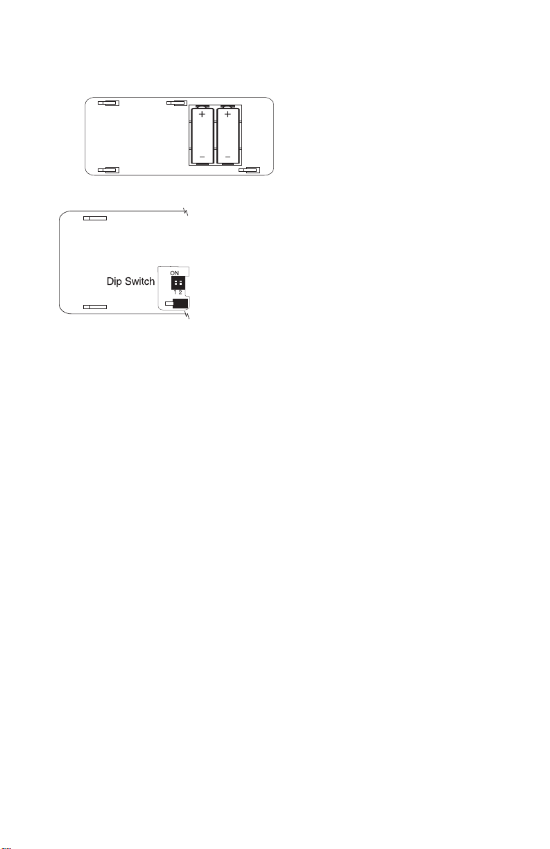
2. Install the batteries positive (+) side first, with the correct polarity, as shown
below.
Setting the Dip Switches
The detector has user-selectable dip switch settings as
shown.
Dip Switch 1– Not Used
Dip Switch 2– Level 1/Level 2 Detection
This is a sensitivity selection dip switch which may be
used to optimize false alarm immunity for certain
acoustic environments.
Switch 2 = OFF). This is the highest sensitivity setting for the detector, and will be
suitable for most applications.
For rooms which are smaller, and contain a significant number of sound-reflective
surfaces (such as bathrooms, kitchens, entrances, etc.), Level 2 detection (Dip
Switch 2=ON) provides a reduced sensitivity setting which may be more appropriate.
The detector is factory set for Level 1 detection (Dip
Selecting a Mounting Location
The detector is omnidirectional, providing 360 degree coverage. Coverage is
measured from the center of the detector to the point on the glass farthest from
the detector.
Guidelines for optimizing detection and avoiding false alarms
• For optimum protection, the detector should have a direct line of sight to the
protected glass.
• Window coverings will absorb sound from the shattering glass. In these
cases, mount the detector as close as possible to the protected glass, either
on an adjacent wall, the ceiling, or behind the window covering if possible.
• The detector should be mounted at least 1.8m (6 feet) off the ground.
• Do not mount the detector on the same wall as the protected glass.
• Avoid installation near noise sources, such as speakers or other objects
which produce sounds continuously.
• Do not install the detector beyond the maximum recommended range, even
if the AFT–100 simulator shows additional range - future changes in room
acoustics could reduce the range.
• Application on 24 hour loops should be avoided unless the location is
unoccupied.
• Test false alarm immunity by creating any sounds in the room which will
likely occur when the alarm system is armed.
Note: T est the detec tor tho roug hl y f or pr oper plac ement u sing the AFT-100
Glassbreak Simulator. Other simulators may trip the unit, but will not provide accurate test results.
 Loading...