

Tyco Safety Canada 00NB907 User Manual
Metal will block/reflect a wireless signal. DO NOT mount the WLS907, or any
other wireless component, on or near large metal objects (i.e. metal doors, metal
window blinds). Instead, find a close location that provides ‘good’ test results
and use the external contacts instead of the built-in reed switch. Try to avoid
mounting the wireless receiver in a basement or near large metal surfaces (i.e.
metal ductwork) as this can reduce the range.
Using External Contacts
The external contact terminals can be used to connect external contacts or other
switches/devices to the universal transmitter. Install the additional device as per
the manufacturer’s instruction. Connect the device to the contact terminals of the
WLS907. The input is normally closed and is not supervised.
The wires connecting the external device to the input terminals can be any
provided that the resistance of the wire does not exceed 100
length
WW
W
.
WW
Only one contact can be used. If an external contact is used, do not install the
magnet.
Tamper Switches
There are two tamper switches on the WLS907 board. Both removing the cover and/or
removing the WLS907 from its mounting location will cause a zone tamper. See your
panel installation manual for more information on trouble conditions.
Enrolling a WLS907
On the back of the door contact housing, there will be two serial numbers, a five
digit and six digit. Please refer to your receiver installation manual for information
on which serial number should be enrolled.
FCC COMPLIANCE STATEMENT
CAUTION: Changes or modifications not expressly approved by Digital Security Controls Ltd. could void your authority to
use this equipment.
This equipment generates and uses radio frequency energy and if not installed and used properly, in strict accordance with the
manufacturer’s instructions, may cause interference to radio and television reception. It has been type tested and found to
comply with the limits for Class B device in accordance with the specifications in Subpart “B” of Part 15 of FCC Rules, which
are designed to provide reasonable protection against such interference in any residential installation. However, there is no
guarantee that interference will not occur in a particular installation. If this equipment does cause interference to television or
radio reception, which can be determined by turning the equipment off and on, the user is encouraged to try to correct the
interference by one or more of the following measures:
•
Re-orient the receiving antenna
•
Relocate the alarm control with respect to the receiver
•
Move the alarm control away from the receiver
•
Connect the alarm control into a different outlet so that alarm control and receiver are on different circuits.
If necessary, the user should consult the dealer or an experienced radio/television technician for additional suggestions. The user may find the following booklet prepared by the FCC helpful: “How to Identify and Resolve Radio/
Television Interference Problems”. This booklet is available from the U.S. Government Printing Office, Washington,
D.C. 20402, Stock # 004-000-00345-4.
Limited Warranty
Digital Security Controls Ltd. warrants that for a period of twelve months from the date of purchase, the product shall
be free of defects in material and workmanship under normal use and that in fulfillment of any breach of such warranty,
Digital Security Controls Ltd. shall, at its option, repair or replace the defective equipment upon return of the
equipment to its repair depot. This warranty applies only to defects in parts and workmanship and not to damage
incurred in shipping or handling, or damage due to causes beyond control of Digital Security Controls Ltd. such as
lightning, excessive voltage, mechanical shock, water damage, or damage arising out of abuse, alteration or improper
application of the equipment.
The foregoing warranty shall apply only to the original buyer, and is and shall be in lieu of any and all other warranties,
whether express or implied and of all other obligations or liabilities on the part of Digital Security Controls Ltd. This
warranty contains the entire warranty. Digital Security Controls Ltd. neither assumes, nor authorizes any other person
purporting to act on its behalf to modify or to change this warranty, nor to assume for it any other warranty or liability
concerning this product.
In no event shall Digital Security Controls Ltd. be liable for any direct , indirect or consequential damages, loss of
anticipated profits, loss of time or any other losses incurred by the buyer in connection with the purchase, installation
or operation or failure of this product.
Warning:
However, despite frequent testing, and due to but not limited to, criminal tampering or electrical disruption, it is
possible for this product to fail to perform as expected.
Digital Security Controls Ltd. recommends that the entire system be completely tested on a regular basis.
© 2000 Digital Security Controls Ltd., Toronto, Canada
Tech. Line: 1-800-387-3630 • www.dscgrp.com
Printed in Canada 29003039 R005
WLS907NB433
Wireless Door/Window Contact
INSTALLATION INSTRUCTIONSINSTALLATION INSTRUCTIONS
INSTALLATION INSTRUCTIONS
INSTALLATION INSTRUCTIONSINSTALLATION INSTRUCTIONS
Remove Cover
To remove the cover of the WLS907 universal transmitter, insert a small
screwdriver in the slot on the end of the unit. Push the tab to release the cover.
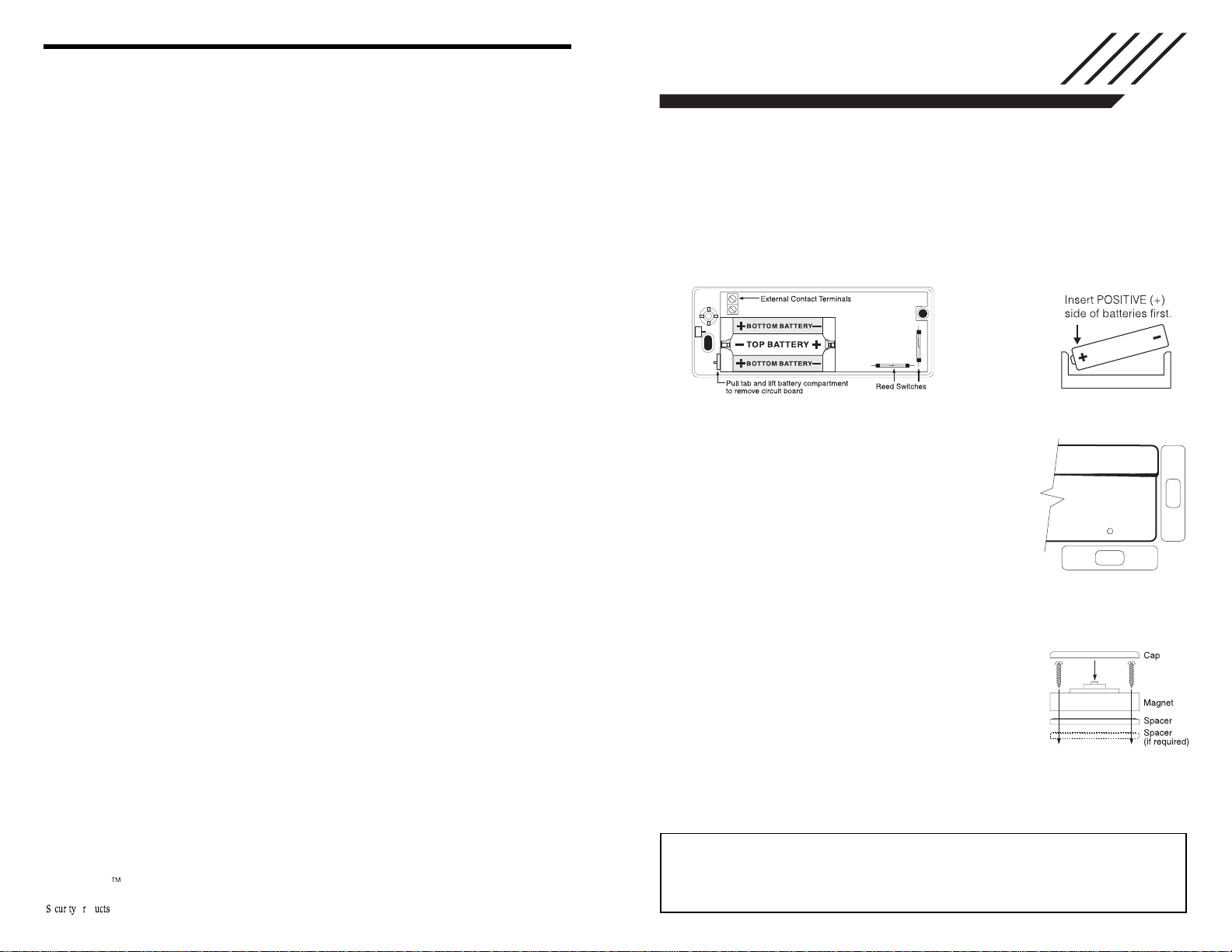
Install Batteries
Use care when installing the batteries. Follow the guidelines below:
1. Observe the correct polarity (see Figure 1).
2. Install the batteries positive (+) side first (see Figure 2).
Use only Eveready Alkaline Energizer batteries. Only replace low batteries with
fresh ones. Always replace all three batteries at the same time.
Figure 1 Figure 2
Find a Location for the Transmitter
Locate where the transmitter is to be mounted. Perform
the Module Placement Test to ensure that the selected
location is in range of the wireless receiver (see
receiver Installation Manual for instructions).
Determine where the magnet will be placed. In order to
activate the reed switch, the magnet must line up with the
end of the transmitter OR the dot on the magnet must line
up with the dot on the edge of the cover(see Figure 3).
Remove Circuit Board
Before mounting the unit, remove the circuit board. Pull the tab located next to the
battery compartment. Gently lift the circuit board out of the plastic (see Figure 1).
NOTE: Do not touch the coils on the circuit board as this may damage the unit.
Mount Transmitter and Magnet
Mount the backplate of the transmitter using the screws
provided and replace the circuit board. The head of the
screw must be below the circuit board so that the sensor is
not shorted out. Use flat-headed screws only. Use wall
anchors if necessary. Replace the cover carefully, so as not
to damage the antenna.
Mount the magnet no more than ¼” from the transmitter. Use
the spacers provided (see Figure 4). Once the unit and magnet are mounted, open
and close the window/door to ensure that none of the parts interfere with this
movement. Only one magnet can be used per transmitter.
• W A R N I N G •
Please refer to the System Installation Manual for information on
limitations regarding product use and function and information on the
limitations as to liability of the manufacturer.
Figure 3
Figure 4
 Loading...