

Tyco Safety Canada 00NB904 Users Guide
WLS904-418
WLS904-433
Wireless Motion Detector
INSTALLATION INSTRUCTIONSINSTALLATION INSTRUCTIONS
INSTALLATION INSTRUCTIONS
INSTALLATION INSTRUCTIONSINSTALLATION INSTRUCTIONS
Each WLS904 motion detector should be located so that it provides
optimal coverage of the intended area. Refer to Changing Motion Detector
Lenses below for information on the four lenses available for the WLS904
Motion Detector. When locating motion detectors, observe the following:
• For the Wall-to-Wall, Corridor and Curtain Lenses, the Mounting Height
should be 6-10 ft./ 2-3 m from the floor. The nominal mounting height is
7.5 ft./ 2.3 m.
• For the Pet Alley Lens only, the Mounting Height should be 4-5 ft./1.2-1.5m
from the floor.
• Do not aim the detector at reflective surfaces such as mirrors or
windows. This may distort the coverage pattern or reflect sunlight
directly onto the detector. Avoid locations where the detector may be
exposed to direct or reflected sunlight.
• Avoid locations that are subject to direct air flow, such as near an air duct outlet.
• Do not locate the detector near sources of steam or oil vapor, such as
a stove or fryer.
• Do not obscure the Detector’s coverage pattern with large objects within
the detection area. If you can’t see the detector, it can’t see you.
• For indoor use only
• Dead zone 6”/15 cm
NOTE: No detector should be mounted without first performing a
module placement test to determine that it is in range of the
wireless receiver. See the Placement Test instructions in the
Instruction Sheet for your receiver, or in the installation manual for
your system.
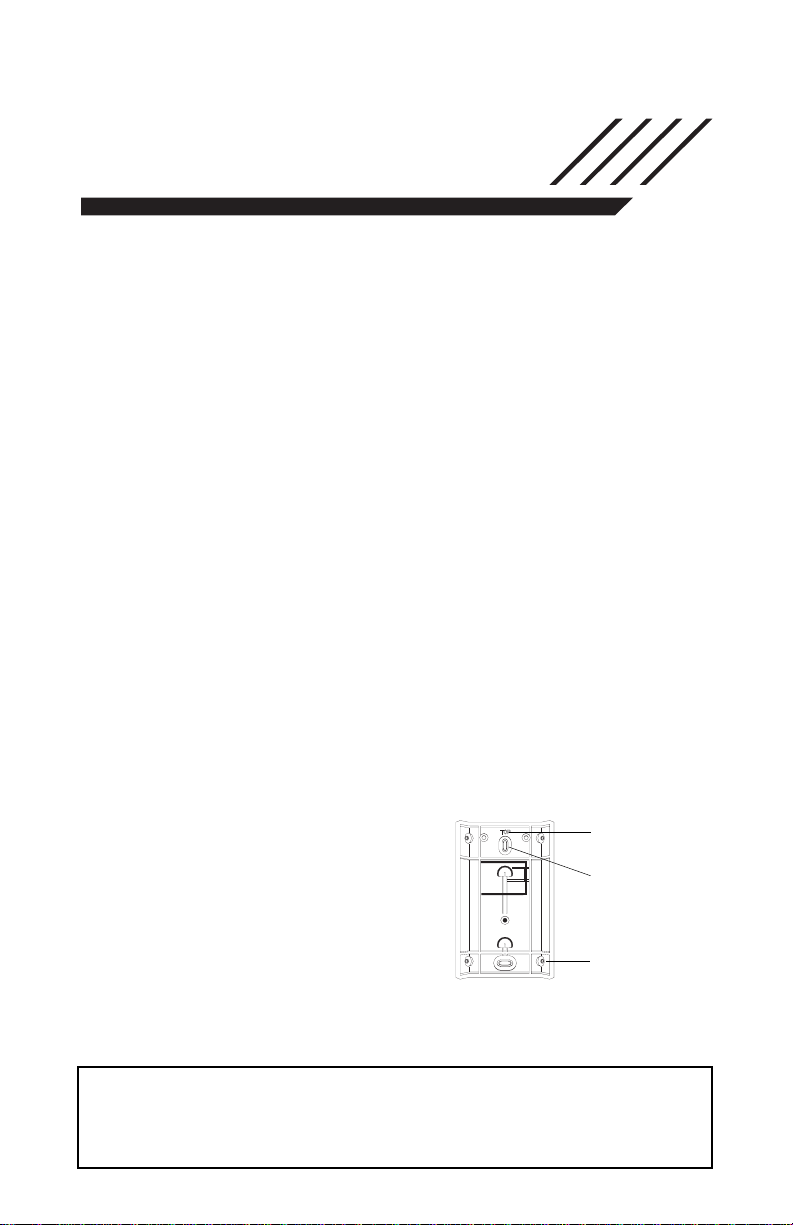
When a location has been determined,
remove the plastic from the mounting
holes and locate the backplate on the
wall and mark screw locations. It is
suggested that wall anchors be used for
all screw locations. Secure the backplate
to the wall, and then secure the enrolled
Detector to its backplate.
Motion Detector Backplate
ENSURE PROPER
ORIENTATION OF
BACKPLATE.
MOUNTING HOLE
KNOCKOUTS
CORNER MOUNTING
KNOCKOUTS
• W A R N I N G •
Please refer to the System Installation Manual for information on
limitations regarding product use and function and information
on the limitations as to liability of the manufacturer.
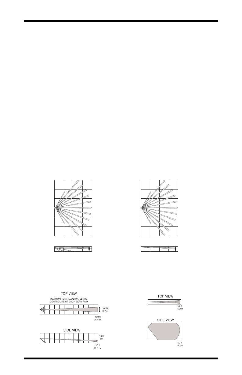
Changing Motion Detector Lenses
Each motion detector is supplied with the Wall-to-Wall lens; three additional
lenses are available for the WLS904 motion detector. The charts on this
page illustrate the range and coverage patterns of each lens.
To change the lens, first open the motion detector by removing the screw in
the bottom of the battery compartment. With the screw removed, pull the
back of the detector away from the front case.
NOTE: The coils and antenna on the motion detector circuit board are very
sensitive components precisely adjusted for maximum performance. Do
not touch the coils or antenna! Even minor distortions can affect the
performance of the motion detector.
Remove the lens holder by pressing down on the top of the holder and pulling
the holder away from the case. When installing the new lens, ensure the
grooved surface faces the interior of the case, and the notches on the lens face
the bottom of the case. Replace the lens holder by snapping it back into place.
Reassemble the motion detector by first engaging the clips on the bottom of
the case. Close the case and then secure the case with the screw in the
bottom of the battery compartment.
Wall-to-Wall Lens Pet Alley
DSC Model BV-L1 DSC Model BV-L4
Range: 50' L × 60' W (16 m × 18 m) Range: 50' L × 60' W (16 m × 18 m)
TOP VIEW
30 ft
9.1 m
15 ft
4.6 m
0ft
0m
15 ft
4.6 m
30 ft
9.1 m
50 ft
SIDE VIEW
15.2 m
15.2 m
50 ft
TOP VIEW
SIDE VIEW
50 ft
15.2 m
50 ft
15.2 m
30 ft
9.1 m
15 ft
4.6 m
15 ft
4.6 m
30 ft
9.1 m
0ft
0m
Corridor Lens Curtain Lens
DSC Model BV-L2 DSC Model BV-L3
Range: 120' L × 10.5' W (36.5 m × 3 m) Range: 50' L × 4.4' W (16 m × 1.3 m)
 Loading...