

Tyco Safety Canada 00NB9001 Installation guide

WARNING
This manual contains information on limitations
regarding product use and function and information
on the limitations as to liability of the manufacturer.
The entire manual should be carefully read.
v1.0
NT9010
NT9010
NT9010 NT9010
v1.0
v1.0v1.0
Installation
Manual
DLS-3 v1.2 and higher
with Driver Pack
®
Security Products

FCC COMPLIANCE STATEMENT
CAUTION: Changes or modifications not expressly approved by Digital Security Controls Ltd. could void your authority to use this equipment.
This equipment has been tested and found to comply with the limits for a Class B
digital device, pursuant to Part 15 of the FCC Rules. These limits are designed to
provide reasonable protection against harmful interference in a residential installation. This equipment generates, uses and can radiate radio frequency energy
and, if not installed and used in accordance with the instructions, may cause
harmful interference to radio communications. However, there is no guarantee that
interference will not occur in a particular installation. If this equipment does cause
harmful interference to radio or television reception, which can be determined by
turning the equipment off and on, the user is encouraged to try to correct the interference by one or more of the following measures:
‘ Re-orient the receiving antenna.
‘ Increase the separation between the equipment and receiver.
‘ Connect the equipment into an outlet on a circuit different from that to which the
receiver is connected.
‘ Consult the dealer or an experienced radio/television technician for help.
The user may find the following booklet prepared by the FCC useful: “How to Identify and Resolve Radio/Television Interference Problems”. This booklet is available
from the U.S. Government Printing Office, Washington D.C. 20402, Stock # 004000-00345-4.
IMPORTANT INFORMATION
This equipment complies with Part 68 of the FCC Rules. On the side of this
equipment is a label that contains, amon g other information, the FCC registration number of this equipment.
Notification to Telephone Company The customer shall notify the telephone
company of the particular line to which the connection will be made, and provide the FCC registration number and the ringer equivalence of the protective
circuit.
FCC Registration Number: F53CAN-xxxx-AL-E
Ringer Equivalence Number: 0.xB
USOC Jack: RJ31X
Telephone Connection Requirements Except for the telephone company provided ringers, all connections to the telephone network shall be made through
standard plugs and telephone company provided jacks, or equivalent, in such a
manner as to allow for easy, immediate disconnection of the terminal equipment.
Standard jacks shall be so arranged that, if the plug connected thereto is withdrawn, no interference to the operation of the equipment at the customer’s premises which remains connected to the telephone network shall occur by reason of
such withdrawal.
Incidence of Harm Should terminal equipment or protective circuitry cause harm
to the telephone network, the telephone company shall, where practicable, notify
the customer that temporary disconnection of service may be required; however,
where prior notice is not practicable, the telephone company may temporarily discontinue service if such action is deemed reasonable in the circumstances. In the
case of such temporary discontinuance, the telephone company shall promptly
notify the customer and will be given the opportunity to correct the situation.
Additional Telephone Company Information The security control panel must be
properly connected to the telephone line with a USOC RJ-31X telephone jack.
The FCC prohibits customer-provided terminal equipment be connected to party
lines or to be used in conjunction with coin telephone service. Interconnect rules
may vary from state to state.
Changes in Telephone Company Equipment or Facilities The telephone company may make changes in its communications facilities, equipment, operations
or procedures, where such actions are reasonably required and proper in its business. Should any such changes render the customer’s terminal equipment incompatible with the telephone company facilities the customer shall be given
adequate notice to the effect modifications to maintain uninterrupted service.
Ringer Equivalence Number (REN) The REN is useful to determine the quantity
of devices that you may connect to your telephone line and still have all of those
devices ring when your telephone number is called. In most, but not all areas, the
sum of the RENs of all devices connected to one line should not exceed five (5.0).
To be certain of the number of devices that you may connect to your line, you may
want to contact your local telephone company.
Equipment Maintenance Facility If you experience trouble with this telephone
equipment, please contact the facility indicated below for information on obtaining
service or repairs. The telephone company may ask that you disconnect this
equipment from the network until the problem has been corrected or until you are
sure that the equipment is not malfunctioning.
Digital Security Controls Ltd. 160 Washburn St., Lockport, NY 14094
AVIS: L’étiquette de l’Industrie Canada identifie le matériel homologué.
Cette étiquette certifie que le matériel est conforme à certaines normes de
protection, d’exploitation et de sécurité des réseaux de télécommunications.
Industrie Canada n’assure toutefois pas que le matériel fonctionnera à la satisfaction de l’utilisateur.
Avant d’installer ce matériel, l’utilisateur doit s’assurer qu’il est permis de le
raccorder aux installations de l’entreprise locale de télécommunication. Le
matériel doit également être installé en suivant une méthode acceptée de
raccordement. L’abonné ne doit pas oublier qu’il est possible que la conformité aux conditions énoncées ci-dessus n’empêchent pas la dégradation du
service dans certaines situations.
Les réparations de matériel homologué doivent être effectuées par un centre
d’entretien canadien autorisé désigné par le fournisseur. La compagnie de
télécommunications peut demander à l’utilisateur de débrancher un appareil
à la suite de réparations ou de modifications effectuées par l’utilisateur ou à
cause de mauvais fonctionnement.
Pour sa propre protection, l’utilisateur doit s’assurer que tous les fils de mise
à la terre de la source d’énergie électrique, les lignes téléphoniques et les
canalisations d’eau métalliques, s’il y en a, sont raccordés ensemble. Cette
précaution est particulièrement importante dans les régions rurales.
AVERTISSEMENT: L’utilisateur ne doit pas tenter de faire ces raccordements
lui-même; il doit avoir recours à un service d’inspection des installations
électriques, ou à un électricien, selon le cas.
L’indice de charge (IC) assigné a chaque dispositif terminal indique, pour
éviter toute surcharge, le pourcentage de la charge totale qui peut être raccordée à un circuit téléphonique bouclé utilisé par ce dispositif. La terminaison du circuit bouclé peut être constituée de n’importe quelle combinaison
de dispositifs, pourvu que la somme des indices de charge de l’ensemble
des dispositifs ne dépasse pas 100.
L’Indice de charge de ce produit est 0.4B.
NOTICE: The Industry Canada label identifies certified equipment. This certification means that the equipment meets certain telecommunications network protective, operational and safety requirements. Industry Canada does
not guarantee the equipment will operate to the user’s satisfaction.
Before installing this equipment, users should ensure that it is permissible to
be connected to the facilities of the local telecommunications company. The
equipment must also be installed using an acceptable method of connection. The customer should be aware that compliance with the above conditions may not prevent degradation of service in some situations.
Repairs to certified equipment should be made by an authorized Canadian
maintenance facility designated by the supplier. Any repairs or alterations
made by the user to this equipment, or equipment malfunctions, may give
the telecommunications company cause to request the user to disconnect
the equipment.
User should ensure for their own protection that the electrical ground connections of the power utility, telephone lines and internal metallic water pipe
system, if present, are connected together. This precaution may be particularly important in rural areas.
CAUTION: Users should not attempt to make such connections themselves,
but should contact the appropriate electric inspection authority, or electrician, as appropriate.
The Load Number (LN) assigned to each terminal device denotes the percentage of the total load to be connected to a telephone loop which is used
by the device, to prevent overloading. The termination on a loop may consist
of any combination of devices subject only to the requirement that the total of
the Load Numbers of all the devices does not exceed 100.
The Load Number of this unit is 0.4B.


Table of Contents
Section 1: Introduction 1
1.1 About the NT9010 System ........................................... 1
1.2 About the NT9010 Manual Set ..................................... 1
1.3 Main system Specifications ........................................... 1
1.4 Additional Devices ........................................................ 2
Section 2: Completing Wiring 3
2.1 AC and Battery Hookups .............................................. 3
2.2 Telephone Connection Terminals - TIP, RING, T-1, R-1 .. 3
2.3 Zone Wiring ................................................................. 3
2.4 Connecting the Remote Sounder .................................. 4
Section 3: Programming the NT9010 5
3.1 How to Enter Advanced Programming .......................... 5
3.2 Programming Decimal Data .......................................... 5
3.3 Programming Hexadecimal Data ................................... 5
3.4 Programming Toggle Options ....................................... 5
3.5 Programming Audio Labels ........................................... 5
3.6 Reviewing Programming ............................................... 6
3.7 Exiting Programming .................................................... 6
Section 4: Changing How the NT9010 Works For Users 7
4.1 Accessing the NT9010 System Using a Telephone ......... 7
4.2 Access Codes ............................................................... 7
4.3 Voice Prompt Interface ................................................. 8
4.4 Alarm Announcements ................................................. 9
4.5 Arming and Disarming Options .................................... 9
4.6 Automatic Arming ........................................................ 9
4.7 Entry and Exit Delay Options ....................................... 10
4.8 Bell Options ................................................................ 10
4.9 User Commands ......................................................... 10
4.10 Function Keys ............................................................. 12
4.11 Programming Wireless Keys and Handheld Keypads ....13
4.12 Fire, Auxiliary, and Panic Keys .....................................13
4.13 Keypad Options ..........................................................14
4.14 Sleep Mode ................................................................14
Section 5: Changing Other NT9010 Functions 15
5.1 Zone Definitions .........................................................15
5.2 Zone Attributes ...........................................................16
5.3 Enrolling Hardwired Zones ..........................................16
5.4 Wireless Device Serial Numbers ...................................16
5.5 Wireless Zone Supervision ...........................................16
5.6 RF Jamming Detection Zone ........................................17
5.7 Zone Tamper/Fault Options .........................................17
5.8 Communicator - Dialing ..............................................17
5.9 Communicator - Telephone Numbers .........................18
5.10 Communicator - Account Codes .................................18
5.11 Communicator - Reporting Formats ............................18
5.12 Communicator - Reporting Codes ...............................20
5.13 Talk/Listen-in Programming .........................................21
5.14 Downloading ..............................................................21
5.15 Telephone Line Monitoring (TLM) ...............................22
5.16 Test Transmissions ......................................................22
5.17 Event Buffer ................................................................23
5.18 Swinger Shutdown .....................................................23
5.19 Timebase ....................................................................23
5.20 Factory Default ...........................................................23
5.21 Installer Lockout .........................................................23
5.22 Walk Test ...................................................................24
Appendix A: Reporting Codes 25
i

NOTES:
ii

Section 1: Introduction
1.1 About the NT9010 System
The NT9010 is a full-featured, wireless security system. It has
been designed for fast and easy installation.
The NT9010 system is made up of the following components:
• a main control unit
• Up to 32 WLS9XX wireless detectors and WLS908 panic pendants (total)
• You can also add up to 16 WLS909 wireless keys, and 4
WLS910 handheld keypads to the system.
The NT9010 system supports up to 32 zones (detectors and
panic pendants), and 32 system users. The NT9010 main control
unit guides users through their available options with easy-tounderstand audio prompts. The status of the NT9010 system can
be monitored over a telephone line.
You can program the system using the NT9010 control unit, or
using DLS-3 downloading software and a computer. If you program the system from the NT9010 control unit, you can do the
basic zone enrollment and programming using the Installation
Wizard. See the Quick Set Up Guide for more information on
using the Installation Wizard.
1.2 About the NT9010 Manual Set
Quick Set Up Guide
This Guide is for people who will be installing NT9010 systems
requiring only basic programming. This will be the case in the
majority of installations. Please review this Guide before beginning your installation. The Quick Set Up Guide covers the following topics:
• An overview of the system
• How to mount and complete basic NT9010 wiring
• How to enroll devices and program the system using the
Installation Wizard
• Basic troubleshooting tips
• Guidelines for placing smoke detectors
Installation Manual
This Manual is for people who will be installing a system that
needs special features or custom programming. If your installation requires more programming than is included in the Installation Wizard, review the relevant sections of this manual for more
information.
Programming Worksheets
Use this booklet to record your zone choices and other programming for the system. Keep this booklet in a safe place for future
reference.
User’s Guide
The User’s Guide provides easy to follow instructions for NT9010
users. This Guide contains instructions on turning the system on
or off, dealing with alarms and emergencies, using advanced
functions, fire safety, and how to replace wireless device batteries.
Installers should also review this manual, in order to properly
instruct the end-users once the installation is complete.
1.3 Main system Specifications
Flexible Zone Configuration:
• 32 fully programmable zones
• 23 zone types, 8 programmable zone options
• Connect up to 2 hardwired zones
Access Codes:
• 38 access codes: 32 user codes, 1 Master code, 2 supervisor
codes, 2 duress codes, and 1 maintenance code
Remote Sounder Output:
• Four-wire supervised connection to optional remote sounder
• Can be wired up to 350ft (105m) from the NT9010 control
unit
• Capable of steady or pulsed siren, voice prompts, and central
station talk/listen-in sessions
EEPROM Memory:
• Will not lose programming or system status on complete AC
and battery failure
Power Requirements:
• Plug-in Transformer = 9VAC, 20VA
• Battery = 6 volt 3.5 Ah minimum rechargeable sealed lead
acid
Digital Communicator Specifications:
• Supports all major formats including SIA, Contact ID, and
20bps formats
• Split reporting of selected transmissions to each telephone
number
• 3 programmable telephone numbers
• 2 system account codes
• DTMF and pulse dialing
• DPDT line seizure
• Anti-jam detection
• Event-initiated personal paging
System Supervision Features
The NT9010 continuously monitors a number of possible trouble
conditions including:
• AC Power Failure (system enters “Sleep” mode on loss of AC
power for longer than 30 seconds)
• Trouble by Zone
• Fire Trouble
• Telephone Line Trouble
• Low Battery Condition
• Remote Sounder Supervisory
• Loss of Internal Clock
• Tamper by Zone
• Failure to Communicate
• Improper Zone Placement
1

False Alarm Prevention Features
• Audible Exit Delay
• Audible Exit Fault
• Urgency on Entry Delay
•Quick Exit
• Swinger Shutdown
• Recent Closing Transmission
• Cross Zone Alarm
• Burglary-verified timer
• Communication Delay
• Rotating Keypress Buffer
Additional Features
• Keypad activated alarm output and communicator test
• Keypad lockout
• 128 event buffer, time and date stamped
• Uploading/downloading capability
1.4 Additional Devices
WLS904 Wireless Motion Detector
The Wireless Motion Detector can be used to include wireless
space protection. The unit comes with four ‘AAA’ batteries.
WLS906 Wireless Smoke Detector
The Wireless Smoke Detector can be used to include wireless
smoke detection. The unit comes with six ‘AA’ batteries.
WLS907 Wireless Universal Transmitter
The Wireless Slimline Universal Transmitter can be used to add
wireless door or window contacts. The unit comes with three
‘AAA’ batteries and has built-in contacts.
WLS908 Wireless Panic Pendant
The Wireless Panic Pendant can be used to include personal wireless protection. The unit comes with 1 mini 12V battery (not user
changeable).
WLS909 Wireless Key
The Wireless Key can be used to include a simple and mobile
method of arming and disarming the system. The unit comes
with three Photo/Electronic 1.5V batteries.
This system can have a maximum of 16 Wireless Keys.
WLS910 Wireless Handheld Keypad
The Wireless Handheld Keypad can be used to include a simple
and mobile method of arming and disarming the system. The
unit comes with three ‘AAA’ batteries.
The system can have a maximum of four Wireless Handheld Keypads.
WLS912 Wireless Glassbreak Detector
The Wireless Glassbreak Detector can be used to include wireless
glassbreak detection. The unit comes with three ‘AA’ batteries.
WLS914 Dual PIR Wireless Motion Detector
The Dual PIR Wireless Motion Detector can be used to include
wireless space protection. The unit comes with four ‘AAA’ batteries.
WLS915 Wireless Universal Transmitter
The WLS915 Wireless Universal Transmitter is a smaller transmitter that can be used for door and window contacts. The unit
comes with three ‘AAA’ batteries and has built-in contacts.
Remote Sounder
You can connect a hardwired remote sounder to the NT9010 system. This sounder provides an additional station for the NT9010
to sound alarms and system status, and for central station talk/
listen-in sessions.
2
Section 2: Completing Wiring
This section describes special options for AC or battery power, and instructions on installing hardwired zones and the remote sounder.
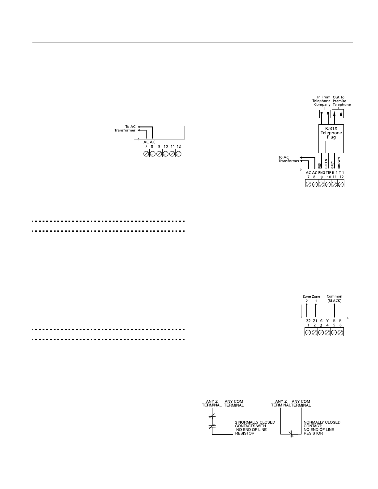
2.1 AC and Battery Hookups
AC Terminals - AC
Connect the AC and telephone line wiring to the terminals
mounted on the NT9010 backplate. When you later attach the
NT9010 to the backplate, the posts on the back of the unit will
plug into the terminals, completing the connection.
For the NT9010 to work correctly,
you will need to connect it to an
AC power source that is not controlled by a switch. The system
comes with a 9V, 20VA plug-in
transformer. Connect the transformer to an unswitched AC source and to the two terminals on
the backplate labelled AC.
The system can be programmed to accept a power line frequency
of either 50Hz AC or 60Hz AC in programming section [701],
option [1].
NOTE:Do not connect the transformer until all other wiring
is complete.
AC Power Line Frequency . . . . . . . . . Section [701], Option [1]
Battery Connection
The battery is used to provide back up power in the event of an
AC power failure and to provide additional current when the system demands exceed the power output of the transformer, such
as when the system is in alarm.
NOTE:Do not connect the battery until all other wiring is
complete.
Connect the RED battery lead to the positive of the battery, the
BLACK battery lead to the negative.
The High Current Charge/Standard Battery Charge option
(section [701], option [7]) allows you to choose between a high
current battery charge and the standard battery charge rate.
High Current/Standard Battery Charge Section [701], Option [7]
2.2 Telephone Connection Terminals - TIP,
RING, T-1, R-1
If a telephone line is
required for central station
communication or for
downloading, connect an
RJ-31X jack to the R-1, T-1,
RING, and TIP terminals on
the backplate as shown
below.
NOTE: Please ensure that all
plugs and jacks meet the
dimension, tolerance and
metallic plating requirements of 47 C.F.R. Part 68,
SubPart F. For proper operation there must be no other
telephone equipment connected between the control
panel and the telephone company facilities.
Do not connect the alarm system communicator to telephone lines intended for use with a FAX machine. These
lines may incorporate a voice filter which disconnects the
line if anything other than FAX signals are detected, resulting in incomplete transmissions.
2.3 Zone Wiring
You can connect up to two hardwired zones to the NT9010. For
the hardwired zones to work correctly, you must enroll them with
the system (see section 5.3 “Enrolling Hardwired Zones” on
page 16). For a complete description of the operation of all zone
types, please see section 5.1 “Zone Definitions” on page 15.
Use the following NT9010 terminals to
make your zone connections:
There are two different ways in which
zones may be wired, depending on
which programming options have been
selected. The system can be programmed
to supervise normally closed, or Single
End of Line loops. Please refer to the following sections to study
each type of individually supervised zone wiring.
Normally Closed (NC) Loops
To enable normally closed loops, programming section [013],
option [1] must be ON.
NOTE: This option should only be selected if Normally
Closed (NC) devices/contacts are being used.
3
Normally Closed Loops . . . . . . . . . . . .Section [013], Option [1]
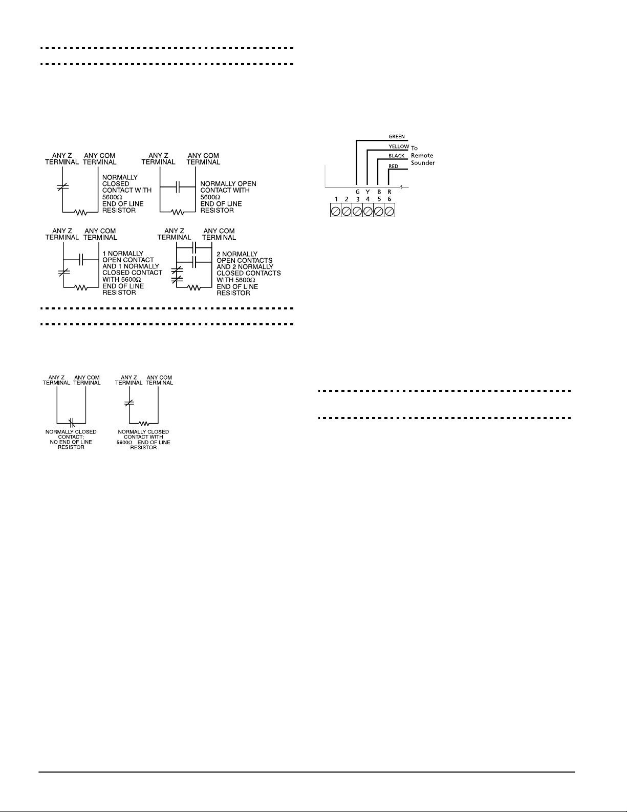
Single End Of Line (EOL) Resistors
To enable system detection of single end-of-line resistors, programming section [013], option [1] must be OFF.
NOTE: This option should be selected if either Normally
Closed (NC) or Normally Open (NO) detection devices or
contacts are being used.
End of Line Resistors . . . . . . . . . . . . . .Section [013], Option [1]
Keyswitch Zone Wiring
Zones may be programmed to be used as keyswitch arming
zones and must be wired according to the following diagram:
2.4 Connecting the Remote Sounder
You can connect a hardwired remote sounder to the NT9010 system. This sounder provides an additional station for the NT9010
to sound alarms and system status, and for central station talk/
listen-in sessions.
Connect the remote sounder to the NT9010 control unit as
shown below:
For the sounder to work on the system you must also turn on the
Remote Annunciation option. When this option is turned on,
the remote sounder will also be supervised.
The Local Annunciation option controls the sounder in the
NT9010 control unit. If you turn this option off, there will be no
alarms or voice prompts from the NT9010. If both options are on,
there will be sound from both the NT9010 and the Remote
Sounder.
If there is a Remote Sounder on the system and it does not report
a supervisory signal within 30 seconds, a “Service Required”
trouble will be generated, and a “Bell Circuit Trouble” event will
be logged in the buffer.
See also section 5.13 “Talk/Listen-in Programming” on page 21.
For a complete description of how keyswitch zones operate, see
section 5.1 “Zone Definitions” on page 15.
Local Annunciation. . . . . . . . . . . . . . . Section [017], Option [4]
Remote Annunciation. . . . . . . . . . . . . Section [017], Option [5]
4

Section 3: Programming the NT9010
The following section of the manual describes how to use the advanced programming sections. For instructions on using the Installation
Wizard, please see the Quick Set Up Guide.
3.1 How to Enter Advanced Programming
You can use the Advanced Programming to set all communicator
and system options. The Installer Code is [5555] at default, but
should be changed to prevent unauthorized access to programming.
NOTE: After you exit from the Installation Wizard or
Advanced Programming, the system will reset itself. This
will take 15 seconds. Do not attempt to perform any system
function during this reset period.
Step 1: From any keypad enter [*][8][Installer Code].
• The System light will flash and the Armed light will turn on to
indicate you are in programming
• The NT9010 will announce “To use the Wizard press 1. To
bypass the Wizard press 2.”
Step 2: To skip the Installation Wizard and go to the advanced
programming sections, press [2].
Step 3: Enter the 3-digit section number you want to program.
• The Armed light will turn off and the Ready light will turn on
to indicate the system is ready for the information for the
selected section
• You can use the Forward (Playback) button to go forwards
through the advanced programming data. The Backward
(Record) button will not work in the advanced programming
sections, except for sections [301] to [303], and [402].
Step 4: Sections [802], [804], or [807] have 2- or 3-digit sub-sections. To access programming in these sections enter the programming sub-section number.
NOTE: If the section number entered is not valid, the
NT9010 will sound an error tone and say the section number that was entered.
Installer Code. . . . . . . . . . . . . . . . . . . . . . . . . . . . Section [006]
3.2 Programming Decimal Data
When the Ready light is ON the NT9010 is waiting for the information to be programmed for the selected section.
If a digit is entered for each program box in a section the system
will automatically exit from the section. It will turn OFF the Ready
light and turn the Armed light back ON.
You can also press the [#] key to exit a section before entering
data for every box. This is handy if you only need to change the
first few program boxes. All other locations in the section will
remain unchanged. If the [#] key is pressed the system will turn
OFF the Ready light, turn ON the Armed light and exit from the
section.
You can use also the Forward (Playback) button to go forwards
through the programming data. The Backward (Record) button
will not work in the advanced programming sections.
3.3 Programming Hexadecimal Data
You may need to enter hexadecimal (HEX) digits for some of the
programming sections. To program a HEX digit press the function
button corresponding to the HEX digit you want to program:
Button Name HEX Digit
Stay A
Away B
Chime C
Exit D
Status E
Vol ume F
If you enter information into a section and make a mistake, press
the [#] key to exit the section. Select that section again and reenter the information correctly.
If you are using a pulse communications format, a decimal zero
[0] does not transmit. Programming a zero [0] tells the system
not to send any pulses for that digit. To make a zero [0] transmit,
it must be programmed as a Hexadecimal ‘A’.
3.4 Programming Toggle Options
Some sections contain several toggle options. Refer to the Programming Worksheets to determine what each option repre-
sents. When you enter a toggle option section, the NT9010
recites the numbers of the options that are currently ON.
Press the number corresponding to the option to toggle it ON or
OFF. Once all the toggle options have been selected correctly
press the [#] key to exit the section and save the changes.
3.5 Programming Audio Labels
You can program audio labels for the system, and for each of the
zones. If you enroll the zones using the Installation Wizard, you
can choose from five pre-set labels for the zone (please see the
Quick Set Up Guide).
Alternatively, you can program custom labels using the advanced
programming sections. To program or change a label:
1. From Advanced Programming, enter section [807].
2. Enter the 3-digit sub-section number of the label ([561], or
[601] to [633]). The system announces the section number
and then recites the words presently programmed in the
label. Each label may have up to six words. The system then
prompts:
“Enter three digit word. To exit, press pound”.
3. Enter the 3-digit code for each word you want to program.
You can enter up to six words for each label. Please see
Appendix A: “Audio Label Library” in the Programming
Worksheets for a list of the 3-digit codes for each available
word. To add numbers to a label, see “Adding Numbers to
Labels” on page 6.
If your label is less than six words,
press [#] at the end of the label.
5
 Loading...