

Tyco Safety Canada 005132XS433 User Manual

• W A R N I N G •
This manual contains information on limitations regarding
product use and function and information on the limitations as to
liability of the manufacturer.
Installation
Manual
PC5132XS-433 NA
Version 5.O

LIMITED WARRANTY
Digital Security Controls Ltd. warrants the original purchaser
that for a period of twelve months from the date of purchase,
the product shall be free of defects in materials and workmanship under normal use. During the warranty period, Digital
Security Controls Ltd. shall, at its option, repair or replace any
defective product upon return of the product to its factory, at
no charge for labour and materials. Any replacement and/or
repaired parts are warranted for the remainder of the original
warranty or ninety (90) days, whichever is longer. The original purchaser must promptly notify Digital Security Controls
Ltd. in writing that there is defect in material or workmanship,
such written notice to be received in all events prior to
expiration of the warranty period. There is absolutely no
warranty on software and all software products are sold as a
user license under the terms of the software license agreement
included with the product. The Customer assumes all
responsibility for the proper selection, installation, operation
and maintenance of any products purchased from DSC. Custom
products are only warranted to the extent that they do not
function upon delivery. In such cases, DSC can replace or
credit at its option.
International Warranty
The warranty for international customers is the same as for
any customer within Canada and the United States, with the
exception that Digital Security Controls Ltd. shall not be responsible for any customs fees, taxes, or VAT that may be due.
Warranty Procedure
To obtain service under this warranty, please return the item(s)
in question to the point of purchase. All authorized distributors
and dealers have a warranty program. Anyone returning goods
to Digital Security Controls Ltd. must first obtain an
authorization number. Digital Security Controls Ltd. will not
accept any shipment whatsoever for which prior authorization has not been obtained.
Conditions to Void Warranty
This warranty applies only to defects in parts and workmanship
relating to normal use. It does not cover:
• damage incurred in shipping or handling;
• damage caused by disaster such as fire, flood, wind, earthquake or lightning;
• damage due to causes beyond the control of Digital Security
Controls Ltd. such as excessive voltage, mechanical shock or
water damage;
• damage caused by unauthorized attachment, alterations, modifications or foreign objects;
• damage caused by peripherals (unless such peripherals were
supplied by Digital Security Controls Ltd.);
• defects caused by failure to provide a suitable installation environment for the products;
• damage caused by use of the products for purposes other than
those for which it was designed;
• damage from improper maintenance;
• damage arising out of any other abuse, mishandling or improper application of the products.
Items Not Covered by Warranty
In addition to the items which void the Warranty, the following
items shall not be covered by Warranty: (i) freight cost to the
repair centre; (ii) products which are not identified with DSC's
product label and lot number or serial number; (iii) products
disassembled or repaired in such a manner as to adversely
affect performance or prevent adequate inspection or testing
to verify any warranty claim. Access cards or tags returned
for replacement under warranty will be credited or replaced
at DSC's option. Products not covered by this warranty, or
otherwise out of warranty due to age, misuse, or damage
shall be evaluated, and a repair estimate shall be provided.
No repair work will be performed until a valid purchase
order is received from the Customer and a Return Merchandise
Authorisation number (RMA) is issued by DSC's Customer
Service.
Digital Security Controls Ltd.’s liability for failure to repair the
product under this warranty after a reasonable number of attempts will be limited to a replacement of the product, as the
exclusive remedy for breach of warranty. Under no circumstances shall Digital Security Controls Ltd. be liable for any special,
incidental, or consequential damages based upon breach of
warranty, breach of contract, negligence, strict liability, or any
other legal theory. Such damages include, but are not limited to,
loss of profits, loss of the product or any associated equipment,
cost of capital, cost of substitute or replacement equipment,
facilities or services, down time, purchaser’s time, the claims of
third parties, including customers, and injury to property. The
laws of some jurisdictions limit or do not allow the disclaimer of
consequential damages. If the laws of such a jurisdiction apply
to any claim by or against DSC, the limitations and disclaimers
contained here shall be to the greatest extent permitted by law.
Some states do not allow the exclusion or limitation of incidental
or consequential damages, so that the above may not apply to you.
Disclaimer of Warranties
This warranty contains the entire warranty and shall be in lieu
of any and all other warranties, whether expressed or implied
(including all implied warranties of merchantability or fitness
for a particular purpose) and of all other obligations or liabilities on the part of Digital Security Controls Ltd. Digital Security Controls Ltd. neither assumes responsibility for nor
authorizes any other person purporting to act on its behalf to
modify or to change this warranty, nor to assume for it any
other warranty or liability concerning this product.
This disclaimer of warranties and limited warranty are governed by the laws of the province of Ontario, Canada.
WARNING: Digital Security Controls Ltd. recommends
that the entire system be completely tested on a regular
basis. However, despite frequent testing, and due to, but
not limited to, criminal tampering or electrical disruption, it is possible for this product to fail to perform as
expected.
Out of Warranty Repairs
Digital Security Controls Ltd. will at its option repair or replace out-of-warranty products which are returned to its
factory according to the following conditions. Anyone
returning goods to Digital Security Controls Ltd. must first
obtain an authorization number. Digital Security Controls
Ltd. will not accept any shipment whatsoever for which prior
authorization has not been obtained.
Products which Digital Security Controls Ltd. determines to
be repairable will be repaired and returned. A set fee which
Digital Security Controls Ltd. has predetermined and which
may be revised from time to time, will be charged for each
unit repaired.
Products which Digital Security Controls Ltd. determines
not to be repairable will be replaced by the nearest equivalent product available at that time. The current market price
of the replacement product will be charged for each replacement unit.

Table of Contents
C O N T E N T S
Introduction 1
1.1 How to use this Manual ....................................................................... 1
1.2 Specifications and Features ............................................................... 1
1.3 Compatible Wireless Devices ............................................................. 2
1.4 Batteries ............................................................................................... 2
PC5132 Set up & Wiring 3
2.1 Unpack the PC5132 ............................................................................ 3
2.2 Choose a Mounting Location for the PC5132 .................................... 3
2.3 Antennas ............................................................................................. 3
2.4 Connect the PC5132 Receiver ........................................................... 3
Enrolling Wireless Devices 4
3.1 A Note about Electronic Serial Numbers ............................................ 4
3.2 Enrolling Wireless Devices ................................................................. 4
3.3 Enroll & Program Wireless Keys (WLS9X9-433) ................................. 4
3.4 Identified Wireless Keys ...................................................................... 6
Other Programming 7
4.1 Program Zones and Partitions ............................................................. 7
4.2 Enable PC5132 Supervision ............................................................... 7
4.3 Enable Supervision of Wireless Zones ................................................ 8
4.4 Jamming Signal Detection .................................................................. 8
4.5 PC5132 Software Default .................................................................... 9
4.6 Deleting Wireless Devices .................................................................. 9
Testing & Mounting 10
5.1 Test the Reception of Wireless Devices ........................................... 10
5.2 Mount the PC5132 and Wireless Devices ........................................ 11
Additional Notes 13
6.1 Trouble Conditions ............................................................................ 13
6.2 Jamming Signal Detection ................................................................ 13
6.3 Wireless Zone Low Battery Transmission ......................................... 13
Troubleshooting 15
Programming Worksheets 16
Guidelines for Locating Smoke Detectors 21
Index 22

Thank you for purchasing the PC5132 Wireless Receiver. This product
is the result of several years of development and will allow you to connect
up to 32 wireless detection devices to the PC585, PC1565, and the Power series
control panels.
The PC5132 operates at 433 MHz. It provides several advantages:
• supervisory transmissions are sent every 12 minutes.
• programmable supervisory window can be as long as 24 hours
• diversity antenna arrangement for better RF reception
In addition, the PC5132 features:
• 6 digit serial numbers for all wireless devices: These new serial numbers
include hexadecimal digits.
Serial Numbers (ESN)” for more information on enrolling 6-digit devices.
We are confident you will find the PC5132 Wireless Receiver a unique and useful
control panel enhancement.
Please read Section 3.1 “A note on Electronic

Introduction
S E C T I O N 1
This manual describes how to install, program and maintain the PC5132.
Before you install the PC5132 module, you should have completed the following
steps in your system installation:
1. Plan the installation and wiring of the security system (see your system
Installation Manual
2. Install the control panel, and install and enroll at least one keypad to use
for programming.
3. Install and enroll any hardwired zone expander modules (PC5108) you
plan to use.
NOTE: PC5108 zone expander modules occupy zones in 2 groups of 4 (e.g.
zones 9-12 and zones 13-16). None of the zones assigned to a PC5108 module may be used for wireless devices.
Program the PC5132 from a system keypad or using downloading software on
a remote computer (e.g., DLS-3). Read your system
information.
1.1 How to use this Manual
Read this manual before you begin installing the PC5132. To install and set up the
PC5132 and wireless devices, follow these steps. Refer to the sections listed below.
1. Temporarily mount and wire the PC5132 module (see
2. Enroll and program wireless devices (see
3. Complete zone and other programming on the system (see
4. Test the placement of all the wireless devices
5. Permanently mount the PC5132 receiver and wireless devices
For additional information on trouble conditions, RF jamming signal detection and
battery replacement, see
For help with troubleshooting, see
1.2 Specifications and Features
• Current Draw: 40mA
• Frequency: 433 MHz
• Zones - receiver can receive signals from up to 32 wireless zones and 16
wireless keys
• Internal antenna
• Supervisory - programmable supervisory window, 2 to 24 hours, in 15
minute increments
• Location
- can be wired up to 750 ft. / 230 m from the main panel with 22 gauge wire;
the wiring used in this circuit connection must be insulated with PVC, TFE,
PTFE, FEP, Neoprene or Polymide
- connects to Keybus
- for longer wire runs, thicker gauge wire must be used.
• Compatibility: The PC5132 v5.X can be connected to the following panels:
PC5020, PC501X, PC1565, PC585
)
Section 6.
Section 7.
Installation Manual
Section 3
)
(see Section 5)
Section 2
Section 4
(see Section 5)
for more
)
)
1

I N T R O D U C T I O N
1.3 Compatible Wireless Devices
Please refer to the Instruction sheets of the following devices for more information.
The PC5132 v4.0 can receive signals from the following devices:
• WLS904-433 Motion Detector • WLS909-433 Wireless Key
• WLS904P-433 Pet Immune PIR • WLS912L-433 Glass Break Detector
• WLS906-433 Smoke Detector • WLS919-433 Wireless Key
• WLS907-433 Universal Transmitter • WLS925L-433 Mini Door/Window Contact
1.4 Batteries
The wireless devices, with the exception of the WLS925L-433 transmitter and
the WLS919-433 Wireless Key, are designed to use only Energizer Alkaline
batteries (by Eveready).
NOTE: Do not use other brands of batteries. Using any other brand may affect
system operation.
2
PC5132 Set up & Wiring
S E C T I O N 2
This section describes how to set up and wire the PC5132 module.
2.1 Unpack the PC5132
Check that the following parts are in your PC5132 package:
• PC5132 PCB •Hardware for mounting the cabinet
• PC5132 plastic cabinet
2.2 Choose a Mounting Location for the PC5132
NOTE: Mount the PC5132 receiver and wireless devices after you have done placement tests with the wireless devices (see sections 5.1 and 5.2).
Find a place that is:
• Dry
• Central to the proposed placement of all wireless devices
• As high as possible
• Far from sources of interference, including: electrical noise such as
computers, televisions and electric motors in appliances and heating and
air conditioning units; large metal objects like heating ducts and plumbing
which may shield the antenna.
Make sure that electrical wires will not run over the antenna(s) of the module when
it is mounted.
When mounting the PC5132 in a basement, place the module as high and as close
to the underside of the first floor as possible. The range of the module will be
reduced if the unit is mounted below ground level.
2.3 Antennas
The antennas have been installed at the factory. They should NOT be adjusted.
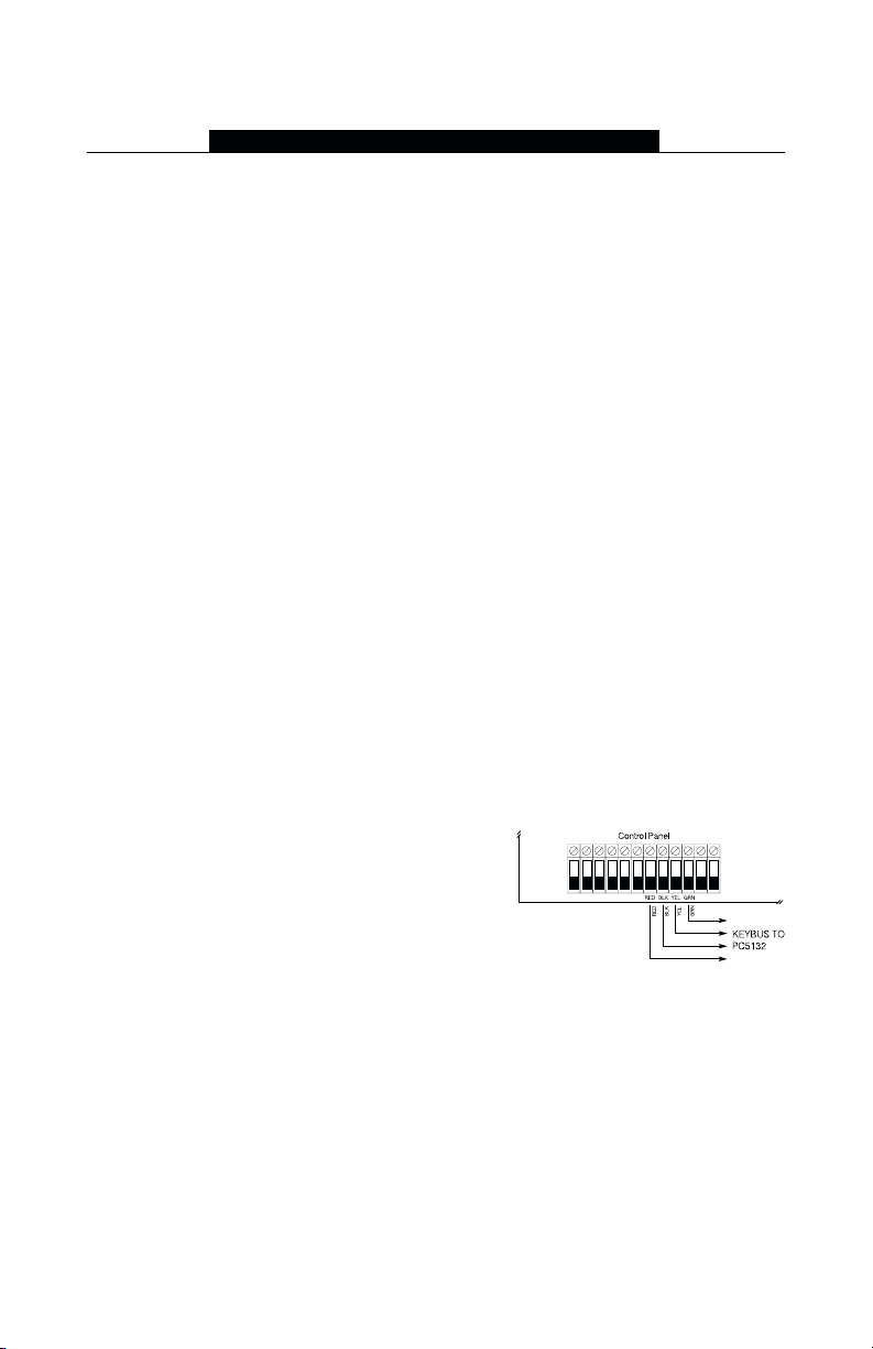
2.4 Connect the PC5132 Receiver
CAUTION: Remove all power from the system while connecting modules to the
Keybus.
Connect the PC5132 to the four-wire Keybus of
the control panel according to the diagram.
After you have completed the wiring, reconnect the power to the security system.
Now that you have wired the PC5132, you should enroll and program the wireless
devices. See section 3 for instructions.
3

Enrolling Wireless Devices
S E C T I O N 3
This section describes how to enroll wireless devices (WLS904-433, WLS904P433, WLS906-433, WLS907-433, WLS912L-433 and WLS925L-433), and wireless
keys (WLS909-433/WLS919-433). For more information on these devices, read the
instruction sheet included with each device.
3.1 A Note about Electronic Serial Numbers
An electronic serial number (ESN) is printed on the back of each wireless device.
ESNs are used to enroll the wireless devices with the PC5132 receiver.
In order to reduce the occurrence of wireless devices with the same serial number,
6-digit serial numbers are now printed on the back of each wireless device. The 6digit serial numbers include hexadecimal digits. For instructions on programming
hexadecimal numbers, see your system
Program’.
NOTE: 6-digit serial numbers are only supported on the following control panels:
PC5020, PC501X, PC1565 and PC585 v2.0 and higher.
The WLS904(P)-433, WLS906-433, WLS907-433, WLS912L-433, and WLS925L-433
devices have both a 5-digit and a 6-digit serial number printed on them. When
connecting the PC5132 to a PC5010 v1.x panel, enter 5-digit serial numbers only. When
connecting the PC5132 to a PC5015 v2.x and higher, PC5020, PC5010, PC1565, or
PC585 panel enter the 6-digit serial number.
3.2 Enrolling Wireless Devices
1. At a system keypad, enter [✱][8][Installer’s code] to go to the Installer
Programming section.
2. Enter programming section [804].
3. Enter the 2-digit number corresponding to the zone the device is to occupy
([01] to [32]).
NOTE: Hardwired and wireless devices cannot be assigned to the same zone.
PC5108 zone expander modules occupy zones in 2 groups of 4 (e.g. zones 9-12
and zones 13-16). None of the zones assigned to a PC5108 module may be used
for wireless devices. For more information on zone assignment, consult your system Installation Manual.
4. Enter the device’s ESN. Follow the instructions in section 3.1 above.
5. Record the serial number and the assigned zone number in the
programming worksheets in the back of this manual.
6. Continue with steps 3 - 5 until you have enrolled all wireless devices.
7. To exit press [#]. The device is now enrolled on the system.
NOTE: The devices will not work properly until you complete zone and partition
programming (see section 4).
Installation Manual
, section 4: ‘How to
4

W I R E L E S S D E V I C E S
3.3 Enroll & Program Wireless Keys
For wireless keys to work on the system, you need to enroll them and then program
the function buttons. Wireless keys are not assigned to zones and require no zone
programming. You can enroll up to 16 wireless keys on the system.
Enroll Wireless keys
1. At a system keypad, enter [✱][8][Installer’s code] to go to the Installer
Programming section.
2. Enter programming section [804].
3. Enter a 2-digit number [41]-[56] to assign the wireless key a slot. These
numbers correspond to wireless key numbers 01-16.
4. Enter the key’s ESN. The entry
digit ESN is being enrolled, add the digit [0] to the beginning of the ESN.
(E.g., if ESN=61234, enter 061234)
5. The key is now enrolled on the system. Record the serial number and the
assigned slot number in the programming worksheets in the back of this
manual.
6. Repeat steps 3 - 5 until all wireless keys have been enrolled.
((
PC5020/PC5020/
7.
(
PC5020/
((
PC5020/PC5020/
Partition 1. To assign keys to Partition 2, enable the appropriate options in
programming sections [91] and [92].
PC501PC501
PC501
PC501PC501
XX
only) only)
X
only) By default, all wireless keys are assigned to
XX
only) only)
NOTE: A wireless key can only be assigned to one partition.
8. To exit press [#].
Program the Wireless Key Function Buttons
WLS909-433/WLS919-433 wireless keys have four programmable function buttons.
You must program a set of four functions for the buttons before any keys will work.
After the functions are programmed, when you press and hold one of the four buttons
for two seconds, the system will execute the programmed function.
For systems not using partitions: program the function buttons in section [59].
All wireless keys will have the same four functions.
For systems using 2 partitions (PC5020/PC501X only): all wireless keys assigned to Partition 1 will have the four functions programmed in section [59]. All
wireless keys assigned to Partition 2 will have the four functions programmed in
section [60]. For example, if function button 1 in Section [59] is programmed for
Stay arming, then pressing the first button on wireless keys assigned to Partition 1
will Stay arm Partition 1.
NOTE: Wireless keys will not work when the partition they are assigned to is being
accessed for zone bypassing or programming.
1. At a system keypad, enter [✱][8][Installer’s code].
2. Enter programming section [804].
3. Enter programming section [59] for keys assigned to partition 1, or [60] for
keys assigned to partition 2.
4. For each of the 4 function buttons, enter the 2-digit number of the function
you want to select. See the programming worksheets in the back of this
manual for a list of function key options.
must
be six digits. If an older key with a 5-
5
 Loading...