

Page 1
Ty-Borealis Series
Three Phase ELI System
8 KW – 48 KW
Operators Manual
M4102 Ty-Borealis 8-48KW Operators Manual v1.0 2013-08-14
Page 2

i
M4102 Ty-Borealis 8-48KW Operators Manual v1.0 2013-08-14
Page 3

Dear Customer,
Thank you for selecting our emergency lighting inverter (ELI). We are
pleased to include you as one of our valued Tycor UPS customers!
We are confident that this emergency lighting inverter system, developed
and satisfaction you demand.
Please read this installation manual carefully as it contains the necessary
information required to install the ELI properly.
Thank you for choosing Tycor UPS.
ii
NOTE
The instructions contained in this manual are not intended to cover all of the
details or variations in equipment, or to provide for every possible contingency
to be met in connection with installation, operation, or maintenance. Should
further information be desired or should particular problems arise which are not
covered sufficiently for the purchaser’s purposes, the matter should be referred
directly to Tycor UPS.
Any electrical or mechanical modifications to this equipment, without prior
written consent of Tycor UPS, will void all warranties and may void UL/cUL
listing. Unauthorized modifications may also result in personal injury, death,
and damage to the equipment.
and manufactured in our ISO 9001 certified facilities, will provide the quality
M4102 Ty-Borealis 8-48KW Operators Manual v1.0 2013-08-14
Page 4
Preface
Congratulations on your choice of our emergency lighting inverter (ELI).
This equipment has been manufactured and tested using methods and procedures
UL 924.
This manual describes the recommended procedures for installing the ELI.
While every effort has been made to ensure the completeness and accuracy of this manual,
the use of the information contained in this document.
We recommend that this manual be kept with the ELI for future reference. If any problems
Centre before proceeding.
This document may not be copied or reproduced without the explicit written permission of
Tycor U P S .
Due to technical advancements and improvements, some of the information contained in
this manual may be changed or modified without prior notice.
iii
equivalent to
Tycor U P S assumes no responsibility or liability for any losses or damages resulting from
WARNING: This manual is intended to provide installation instructions
only. The information contained in this manual is to be used as a guideline
and recommendation only. Only qualified personnel should perform
installation and maintenance. Factory authorized personnel shall inspect
installation prior to start up and commissioning to validate warranty.
Failure to follow this directive will void the warranty.
are encountered with the procedures contained in this manual, please contact our Service
M4102 Ty-Borealis 8-48KW Operators Manual v1.0 2013-08-14
Page 5
Symbols
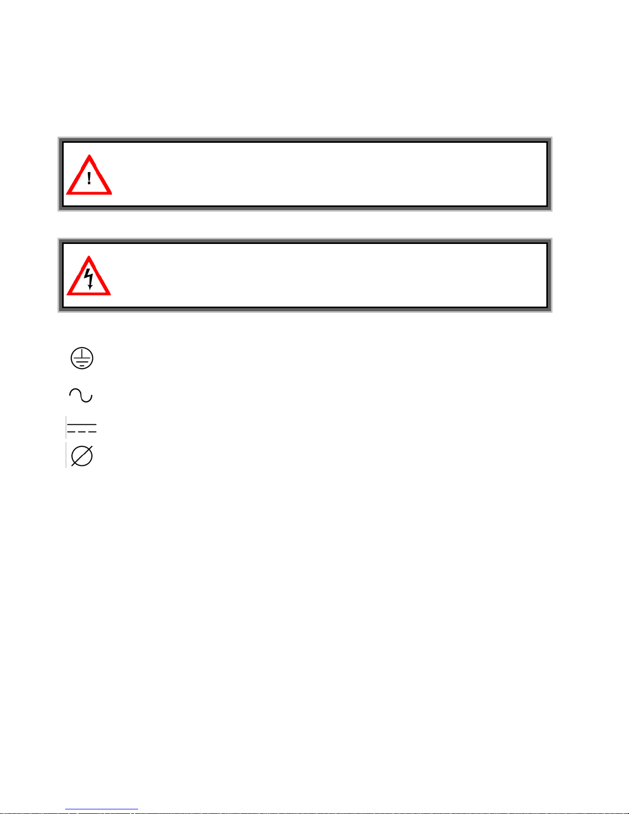
Warning Information
Electrical Hazard
Electrical Symbols
Protective grounding terminal; a terminal that must be connected to ground prior to
making any other connection to the equipment.
A terminal to/from which an alternating current or voltage may be applied/supplied.
A terminal to/from which a direct current or voltage may be applied/supplied.
This symbol indicates the word “phase”.
iv
The following symbols are used through out this manual.
This symbol alerts you to important information.
This symbol indicates an electrical hazard may be present.
M4102 Ty-Borealis 8-48KW Operators Manual v1.0 2013-08-14
Page 6

Safety Instructions
READ AND FOLLOW ALL SAFETY INSTRUCTIONS.
SAVE THESE INSTRUCTIONS.
This manual contains important safety instructions that should be followed during installation
process
operators
to
protect themselves and the equipment being installed.
GENERAL
Move the ELI in an upright position, in its original packaging, to its final destination.
and
be
Do not use this equipment for other than intended use.
-
-
-
-
- - -
-
-
-
-
-
-
v
and maintenance of the ELI system and optional packages. Before the installation
begins, we recommend that the installer read through the safety precautions,
manual and the option installation instructions, taking all necessary safety precautions
-
To lift the cabinets, use a forklift or lifting belts with spreader bars.
-
Check for sufficient floor and elevator loading capacity.
-
Check the integrity of the ELI equipment carefully.
If visible damage is evident, do not attempt to install or start the ELI. Contact the
transport delivery company immediately, file a claim with the transport company
inform Tycor UPS directly.
Do not use outdoors.
The use of accessory equipment not recommended by Tycor UPS may cause an unsafe
condition
WARNING! RISK OF ELECTRICAL SHOCK: use extreme caution when removing
covers.
All maintenance and service work should be performed by qualified and trained service
personnel. The ELI may contain its own energy source, (batteries) which can
dangerous to the untrained person. This ELI contains potentially hazardous voltages
The field-wiring terminals may be electrically live, even when the ELI is not connected to
the utility.
Use caution when servicing batteries. A battery can present a risk of electrical shock,
burn from high short-current. Battery acid can cause burns to skin and eyes. If acid is
spilled on skin or in eyes, flush with fresh water and contact physician immediately.
When replacing batteries use the same number and type (sealed-cell lead acid).
Proper disposal of batteries is required. Refer to your local codes for disposal
requirements.
Dangerous voltages may be present during battery operation. The batteries must be
disconnected during maintenance or service work. (Open battery breaker or fuses)
Be aware that the inverter can restart automatically after the utility voltage is restored.
M4102 Ty-Borealis 8-48KW Operators Manual v1.0 2013-08-14
Page 7

INSTALLATION
This ELI is intended for use in a controlled indoor environment free of conductive
Avoid locations in direct sunlight or near heat sources (gas or electric heaters).
-
-
- - -
- - -
STORAGE
Store the ELI in a dry location free of contaminants;
periodically (time depending on storage temperature).
WARNING!
IS
S
DEATH.
QUALIFIED TO DO SO. AN INSTALLER SHOULD NEVER WORK ALONE.
WARNING!
CAPACITORS TO DISCHARGE BEFORE WORKING ON THE EQUIPMENT.
CAUTION!
necessary to correct the interference.
CAUTION!
cables.
vi
contaminants and protected against any type of intrusion.
Do not install the ELI in an excessively humid environment or near water.
-
Avoid spilling liquids and/or dropping any foreign object(s) onto the ELI.
The unit must be placed in a sufficiently ventilated area; the ambient temperature should
not exceed 40°C (104°F).
Optimal battery life is obtained if the ambient temperature does not exceed 25°C (77°F).
HIGH GROUND LEAKAGE CURRENT: ground connection completed before connecting
the AC voltage wires on the input!
Switching OFF the ELI does not isolate the ELI from the utility as the utility supply is still
HOT at the input terminal strip. Supply breaker needs to be opened.
It is important that air can move freely around and through the unit. Do not block the air
vents.
-
-
Storage temperature must be within -25°C (-13°F) to 55°C (131°F).
-
If the unit is stored for a period exceeding 3 months, the batteries must be recharged
LETHAL VOLTAGES MAY BE PRESENT WITHIN THIS UNIT EVEN WHEN IT
APPARENTLY NOT OPERATING. OBSERVE ALL CAUTIONS AND WARNINGS IN THI
MANUAL. FAILURE TO DO SO COULD RESULT IN SERIOUS INJURY OR
REFER UNIT TO QUALIFIED SERVICE PERSONNEL IF MAINTENANCE IS REQUIRED.
NO ONE SHOULD WORK ON THIS EQUIPMENT UNLESS THEY ARE FULLY
WHEN REMOVING POWER FROM THE ELI, ALLOW FIVE MINUTES
This equipment complies with the requirements in Part 15 of FCC rules for a Class A
computing device. Operation of this equipment in a residential area may cause
interference to radio and TV reception, requiring the operator to take whatever steps
Do not put option control wiring in the same conduit as the ELI input or output power
FOR
M4102 Ty-Borealis 8-48KW Operators Manual v1.0 2013-08-14
Page 8

THIS SAFETY NOTICE IS ADDRESSED TO THE TYCOR UPS
Electrical Safety
•
Maintenance work to be performed by a factory trained customer engineers, or
boards and working inside the unit.
• • • • •
READ AND FOLLOW ALL SAFETY INSTRUCTIONS.
SAVE THESE INSTRUCTIONS.
vii
CUSTOMER ENGINEERS WHO PERFORM MAINTENANCE OF THE
UNINTERRUPTIBLE POWER SUPPLY (ELI) SYSTEMS.
qualified personnel. Extremely dangerous voltage levels can exist within the ELI
system. Extreme caution must be used.
Ensure system is in maintenance bypass mode or external wrap-around bypass
mode before work is started.
This manual is designed as an aid tool in diagnosing problems that may arise.
Tycor U P S does not assume responsibility if information causes injuries.
Apart from the front door, do not open any other part of the ELI without consulting the
factory first. Before removing the protection screens, be sure that the unit is
completely powered off.
Be aware that dangerous voltage can be supplied by the internal battery or
electrolytic capacitors.
When system is in bypass mode and all fuses have been opened dangerous
voltages may exist within the ELI system. Use extreme caution when exchanging
M4102 Ty-Borealis 8-48KW Operators Manual v1.0 2013-08-14
Page 9

1
Introduction ........................................................................................................................................................... 1
1.1
1.3
Overview............................................................................................................................................................................... 1
Definitions............................................................................................................................................................................ 2
2
Theory of Operation............................................................................................................................................. 3
2.1
2.10
General Topology............................................................................................................................................................... 3
Manual Bypass Switch.....................................................................................................................................................10
3
5
Inter-PCB Diagram ............................................................................................................................................. 12
Installation ........................................................................................................................................................... 16
5.1
5.3
Site & Environmental Conditions..................................................................................................................................16
Terminal Strip Connections............................................................................................................................................19
6
7
Front Panel........................................................................................................................................................... 20
Operation.............................................................................................................................................................. 25
7.1
7.6
Switch On Procedure (Authorized Trained Personnel Only) .................................................................................25
Battery Condition Test.....................................................................................................................................................28
8
The LCD Display ................................................................................................................................................. 29
8.1
8.5
Menu 0 – Main Menu.........................................................................................................................................................29
Menu 4 – Historical Event Menu ....................................................................................................................................34
viii
TABLE OF CONTENTS
1.2
Features................................................................................................................................................................................ 1
2.2
Normal Operation Mode ................................................................................................................................................... 4
2.3
Backup Mode ...................................................................................................................................................................... 4
2.4
Reserve Mode ..................................................................................................................................................................... 5
2.5
Manual Bypass Mode ........................................................................................................................................................ 5
2.6
Features and Advantages ................................................................................................................................................ 6
Rectifier ................................................................................................................................................................................ 8
2.7
2.8
Inverter.................................................................................................................................................................................. 9
Static Switch.......................................................................................................................................................................10
2.9
4
Physical Topology ............................................................................................................................................. 13
5.2
Cable Selection..................................................................................................................................................................18
7.2
Shutdown Procedure .......................................................................................................................................................26
7.3
From Inverter To Manual Bypass Procedure .............................................................................................................27
From Manual Bypass to Inverter Procedure ..............................................................................................................28
7.4
Manual Battery Test..........................................................................................................................................................28
7.5
8.2
Menu 1 – Select Menu ......................................................................................................................................................30
Menu 2 – Status Warning Menu.....................................................................................................................................30
8.3
8.4
Menu 3 – Real Time Data Menu .....................................................................................................................................32
M4102 Ty-Borealis 8-48KW Operators Manual v1.0 2013-08-14
Page 10

9 INTERFACE CONNECTIONS ........................................................................................................................... 36
9.1
9.6
Dry Contacts.......................................................................................................................................................................36
Emergency Lighting Notification ..................................................................................................................................38
10
Battery Backup Units (BBU) ............................................................................................................................ 39
10.1 Run Time Charts................................................................................................................................................................41
Options ................................................................................................................................................................. 45
11
11.1
11.5
Emergency Stop Switch ..................................................................................................................................................45
Normally Off Function......................................................................................................................................................45
12
13
Technical Specifications .................................................................................................................................. 46
Contact Information........................................................................................................................................... 50
ix
9.2
Software for PC Monitoring ............................................................................................................................................37
9.3
Emergency Power off Connection ................................................................................................................................37
9.4
DB9 Connectors ................................................................................................................................................................37
9.5
Web Monitoring Module (SNMP Module) ....................................................................................................................37
10.2 BBU Configurations .........................................................................................................................................................43
11.2
Remote Display Panel ......................................................................................................................................................45
12 Pulse Rectifier ..............................................................................................................................................................45
11.3
11.4
External Wrap Around Bypass ......................................................................................................................................45
M4102 Ty-Borealis 8-48KW Operators Manual v1.0 2013-08-14
Page 11

Congratulations on your choice of the Ty-Borealis On-Line Emergency Lighting Inverter
1.1
Overview
required.
1.2
Features
the LCD screen displays critical system information including:
•
•
Percent Load
Internal ELI temperature.
A manual test switch has been incorporated into the input/test breaker that makes
ELI to be performed without interruption of power to the load.
The communications port, in conjunction with multi-platform monitoring and control
Other communications options include:
•
An SNMP adapter to remotely control and monitor the unit via a network or
environments.
•
1
1 Introduction
(ELI). This ELI features the latest top of the line microprocessor technology and IGBT
transistors
sine wave
and provides clean, highly regulated and pulse width modulated (PWM) true
power.
This ELI is designed for installation between your AC power supply (utility or
generator) and your lighting equipment. It provides power to your equipment during
major power events such as blackouts and brownouts, over-voltage and undervoltage conditions. The ELI provides a consistent supply of regulated AC power
during these power events, allowing you to ensure safety and lighting for the period
This ELI provides full time self-diagnostics as well as two levels of audible alarms
when the unit is operating in battery mode. Along with the current mode of operation,
•
•
•
•
•
testing a simple procedure. The internal bypass switch allows maintenance on the
Remaining battery capacity, battery voltage
Input voltage,
Output voltage,
Input frequency,
Output frequency and
software, enables the unit to be connected to a local or networked computer system.
Detailed operating information including voltages, currents, and alarm status is
available to the monitoring system.
the Internet.
An AS-400 interface to allow for relay communications in PLC or dry contact
M4102 Ty-Borealis 8-48KW Operators Manual v1.0 2013-08-14
Page 12

1.3
Definitions
•
Critical Load
Emergency Power Off.
• • • • •
•
• • • • • • •
2
These are loads that require clean, regulated and continuous AC power and
which are connected to the output of the ELI module
ELI Module
The portion of the ELI system that contains one or more of: the rectifier /
DFC, charger, inverter, static bypass switch, maintenance bypass switch,
controls, monitoring, and indicators.
Rectifier / DFC
Contained in the ELI module. Responsible for converting the normal AC input
power to DC power and supplying the inverter with DC power.
Charger
Contained in the ELI module. Responsible for recharging the batteries.
Inverter
Contained in the ELI module. Responsible for converting DC power (supplied
by the rectifier) to regulated and filtered AC power that is then supplied to the
critical loads.
Static Bypass Switch
Contained in the ELI module. Responsible for automatically transferring the
attached load, without interruption, from the inverter AC output to the bypass
AC power source in the event of an overload or degradation of the inverter’s
performance.
Maintenance Bypass Switch:
Contained in the ELI module. Used to transferring the attached load, without
interruption, from the inverter AC output to the bypass AC power source while
electrically isolating the static bypass switch, rectifier / DFC, charger and
inverter. Used for maintenance purposes.
Battery
The battery system provides DC power to the inverter input when the normal
AC input power to the ELI fails.
IGBT
Isolated Gate Bipolar Transistor.
PWM
Pulse Width Modulation.
ELI
Emergency Lighting Inverter.
BBU
Battery Backup Unit.
PFC
Power Factor Correction.
EPO
M4102 Ty-Borealis 8-48KW Operators Manual v1.0 2013-08-14
Page 13
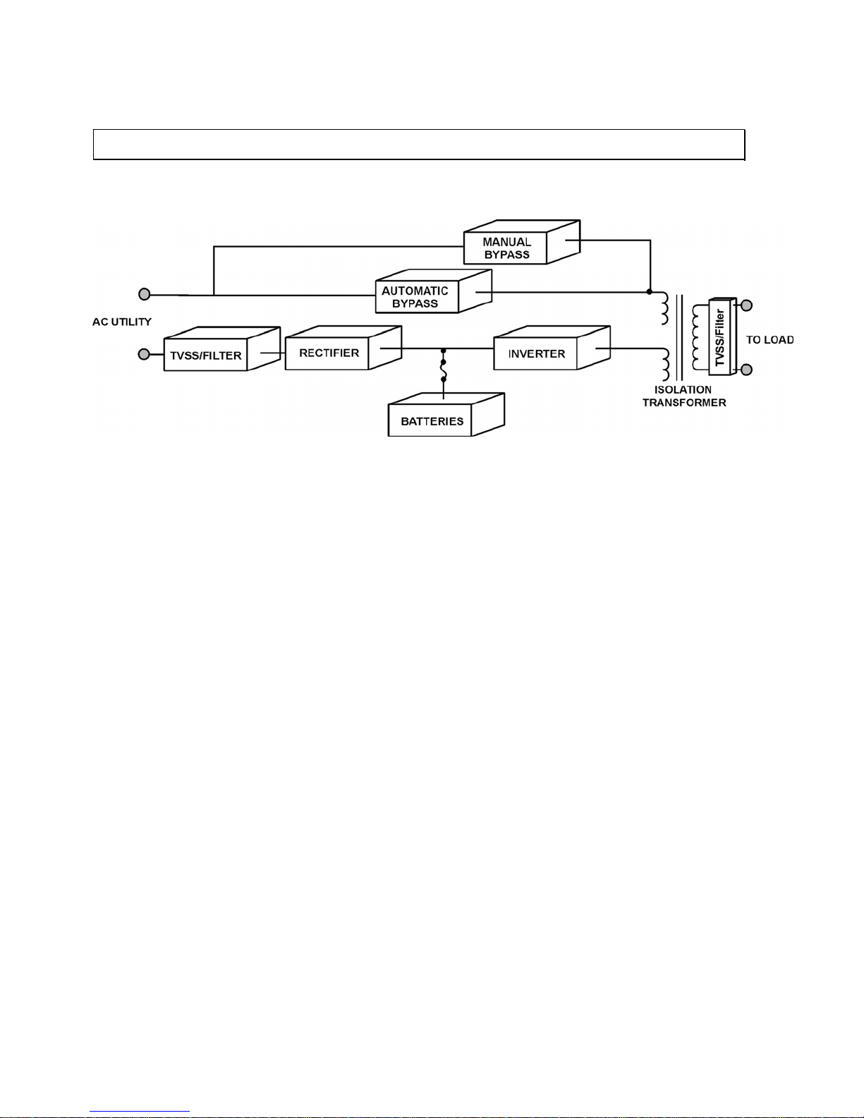
2.1
General Topology
Figure 2.1
General Block Diagram
ELI Module Components:
components:
The ELI module consists of the following major
-
-
Input, Reserve and Bypass circuit breakers
Optional Features:
-
-
12-pulse rectifier and harmonic filter to reduce input harmonic content.
Isolated parallel redundant operation (IPRO)
-
-
Generally, there are four modes of operation for an ELI system, NORMAL MODE,
MODE.
3
2 Theory of Operation
-
Rectifier / Charger
-
Inverter
Microprocessor controlled logic and control panel with alarm indicators and digital
metering display
External battery connection
-
Static bypass
-
Full maintenance bypass
-
Emergency power off (EPO) connection
-
Communications interface
-
SNMP Adapter for network communications and monitoring
-
Input power walk-in
-
Front cable connections
-
Output isolation transformer
-
Additional battery modules for extended runtime
-
Top cable entry
-
Remote display panel
-
Emergency power off switch
-
External maintenance bypass cabinet
BACK-UP (BATTERY) MODE, RESERVE MODE and MAINTENANCE BYPASS
M4102 Ty-Borealis 8-48KW Operators Manual v1.0 2013-08-14
Page 14
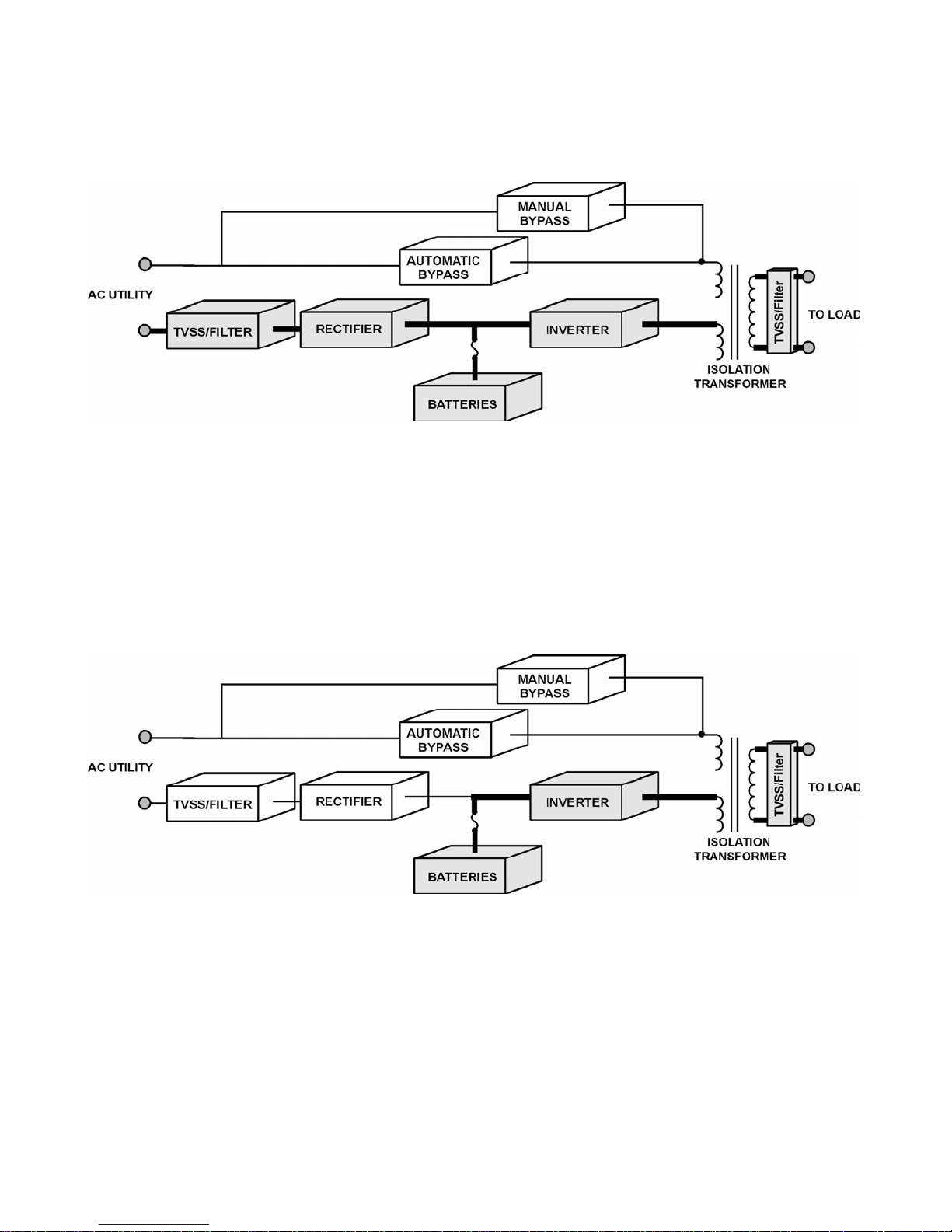
Normal Operation Mode
2.2
Figure 2.2
Normal Mode Operation
The rectifier/charger converts the supplied AC power into DC (bus) power that is
then
is
source is within the specified frequency range.
Backup Mode
2.3
Figure 2.3
n
Upon
power to the inverter and the battery charger to replenish the batteries.
4
then supplied to the inverter and the battery charger. The DC to AC inverter
supplies continuous, noise free AC power to the critical loads. The inverter output
synchronized with the bypass AC power source provided that the bypass AC power
Back-up Mode Operation
As the batteries are connected to the DC bus they supply energy to the inverter via
this DC bus, the AC power will remain constant and continuous without interruptio
to the loads when the AC fails or falls out side of the operating parameters.
return of the supplied AC input power the ELI. The rectifier will aut omat ically assume
the DC load (charger, inverter) from the batteries. The ELI will simultaneously supply
M4102 Ty-Borealis 8-48KW Operators Manual v1.0 2013-08-14
Page 15
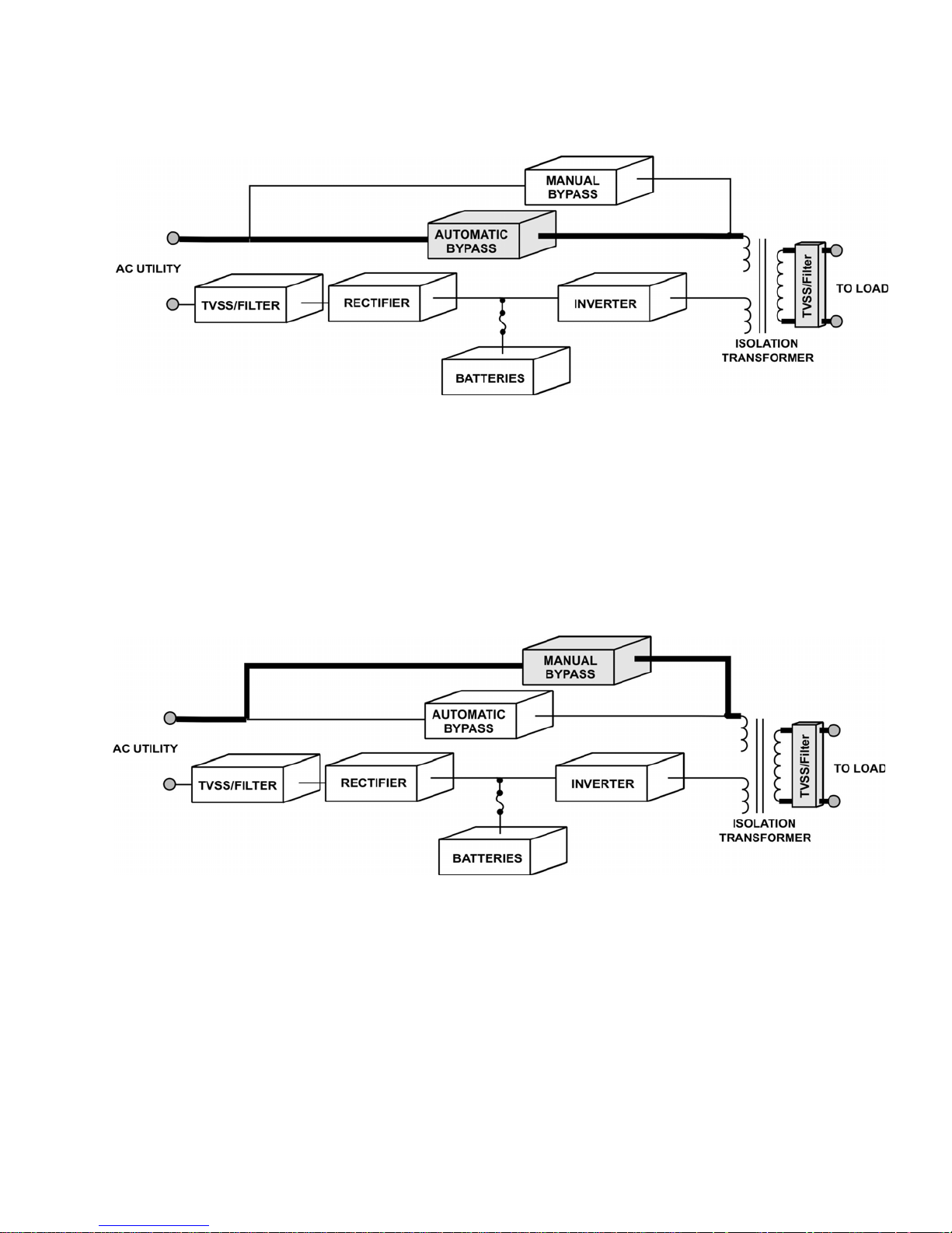
Reserve Mode
2.4
Figure 2.4
Reserve Mode Operation
If the inverter is placed into an abnormal condition, such as over temperature,
to
interruption of the AC output.
Manual Bypass Mode
2.5
Figure 2.5
Manual Bypass Mode Operation
During ELI service procedures or battery replacement, the loads cannot be
close
the loads.
5
short circuit, abnormal output voltage or is overloaded for a period which
exceeds the inverter’s limits, the inverter will automatically shutdown in order
protect itself. If the AC utility power is within the normal parameters, the static
switch will automatically transfer the load to the reserve (utility) source without
interrupted, and as such the technician needs to turn off the inverter switch,
the bypass breaker and then open the rectifier and reserve (utility) breakers. The
ELI is now running in Manual By-pass mode supplying utility AC to the loads. The
AC output will not be interrupted during the manual bypass transfer procedure
because the manual bypass switch is designed to supply continuous power to
M4102 Ty-Borealis 8-48KW Operators Manual v1.0 2013-08-14
Page 16

Features and Advantages
2.6
a.
Reliable input protection: Circuit breakers are in each input loop to ensure
caused by abnormal conditions in either the rectifier or the load.
b.
Input surge protection: Input surge protection is added at the input to
s
that are being turned on and/or off.
c.
EMI suppression: An EMI filter is added to meet the international EMC limits
connected to the same AC source.
d.
Ruggedness: The rectifier employs phase control technology to regulate the
PFC circuit also assist in maintaining the input waveform.
e.
High frequency design: The inverter design incorporates high frequency,
DC
acoustic noise, size and weight.
f.
True galvanic isolation: The isolation transformer addresses ground
mode of operation.
g.
PNP modular design: The circuit boards are designed into several modules,
easy replacement in the field when necessary and eliminate field diagnostics.
h.
Cold start function: The ELI can be started without the utility AC supply
designed
ELI on battery DC power.
i.
Multi-CPU design: Several CPU’s are designed into the control circuit.
reliability and up-times by eliminating field problems.
6
power can continue through the other loops in the event of a breaker trip
provide enhanced protection to both the ELI and the load and also protect
against lightning effects and/or surges caused by large cycling loads or those
to ensure that No noise will effect or interfere with other equipment
DC bus voltage allowing the batteries to be charged while supplying DC
power to the inverter. This has been proven to be the most efficient method
to control and regulate the charge on the batteries. The SCR technology and
highly efficiency Insulated Gate Bi-polar Transistors (IGBT). A PWM wave,
synchronized to the bypass input, triggers the IGBT’s, which invert the
into AC power required by the loads. This design decreases the number of
required components, increases reliability and performance while decreasing
differentials between the input and output, and prevents ground leakage
current problems, common mode and normal mode noise. This transformer is
located on the output side of the ELI system providing isolation under every
which are plugged into slots in the ELI. These plug-able modules allow for
being activated. Or present at the input terminal strip because our
system is designed with current limiting circuitry, which allows Startup of the
These critical functions are designed with multi-level redundancy increasing
M4102 Ty-Borealis 8-48KW Operators Manual v1.0 2013-08-14
Page 17

j.
Protection against possible operator error: The ELI is designed with
causing possible damage.
k.
Wide input range: The components are overrated by design to handle high
Tycor
today’s market.
l.
Harsh environment: Each component of the ELI is chosen with the highest
specifications related to temperature, humidity, altitude, surge or noise.
m.
Intelligent charger: The ELI will automatically recharge (boost charge) the
begins.
n.
Intelligent battery test: The batteries are tested after every boost charge
be informed immediately through alarms on the ELI system.
o.
Charging rate: The charging rate is selectable (L/M/H) according to Ah
banks without adding an additional charger (up to 8hr. back-up).
p.
MTBF of cooling fans: Long cycling fans will operate at variable speeds
increasing the life expectancy of the fan motors.
q.
Redundant power supply: Redundant power supplies have been installed
to allow for worry free operation of the system.
r.
Intelligent interface: One rem ote control panel (or one PC) can monitor and
transmitted to external modules through four RS-485 ports.
s.
Data log capability: All abnormal conditions will be stored within the ELI
abnormal
for servicing.
7
breaker on/off sensors and power supply sensors. These sensors prevent
potential operational mistakes from interfering with the start –up operation
input voltages and currents without harm to the s ystem, ensuring that
UPS ELI’s remain one of the most reliable ELI Systems available in
degree of safety margins allowing for wider environmental parameters and
batteries when the battery voltage level decreases to approximately 2V/Cell
or to a user specified level. To prevent the over-charging of the battery, the
boost charge will stop when batteries achieve a 90% charged level or the
ambient temperature reaches 35oC (95oF) at which point the float charging
whether the charge has been initiated by a battery discharge state (2V/Cell)
or by the regular battery test performed by the ELI (monthly test). When an
abnormal condition (low charge rating, or bad battery) is found the user will
ratings of the batteries. The charger is designed to charge the larger battery
necessary which is d e pendent on the ambient temperature of th e E LI syst em
control up to ninety-nine ELI’s. The communication allows for N+1
redundancy, whereby if one system encounters an emergency or fault
condition, it will warn the user immediately and the load is automatically
transferred to the other ELI systems. The ELI status, data or commands are
control interface board for further reference by the user. Each
condition is time and date stamped (real-time clock) as the event occurs. This
history is stored and cannot be removed even if or when the ELI is turned off
M4102 Ty-Borealis 8-48KW Operators Manual v1.0 2013-08-14
Page 18

t.
Convenient front panel design: The LCD display and control switches are
is password protected.
u.
Emergency stop: In the event of an emergency the ELI can be shutdown
detector signal (optional).
Rectifier
2.7
The main function of a rectifier is to convert the AC input power to DC power. The
supplies the inverter.
Figure 2.6
Rectifier Function
The rectifier design used in the 8KW to 48KW ELI’s include a 6-pulse full
affecting any part of the ELI system.
Additionally, over and under-voltage protection is added to improve reliability and
to
handle extreme ranges of high voltage and high current (–25% to +25%).
8
accessible through the up, down, and enter switches below the front panel
window. All the viewable parameters can be read without opening the front
door. The inverter on/off switch is protected from accidental operation by
being located behind the locked front door although the inverter can still be
switched on and off via the control switches on the front panel but this feature
(no AC at the output) either through a switch (optional) or through a smoke
DC power is then used to charge the batteries, supply the DC bus, which in turn
controlled rectifier. Power Factor Correction (PFC) has been added to maintain a
high input power factor, independent of the load power factor. This 6 pulse
rectifier smoothes the current waveform and reduces the harmonic content
reflected back to the utility. The control circuit regulates the DC bus to within 1%
of the nominal voltage. Soft walk-in circuitry (approximately 20 seconds) and
current limiting circuitry are used to prevent over current or surge currents from
to shutdown the rectifier in the event of abnormal conditions. The DC bus is
adjustable to allow for different types and capacities of batteries. The power
components used within the rectifier are specially designed and selected
M4102 Ty-Borealis 8-48KW Operators Manual v1.0 2013-08-14
Page 19

Inverter
2.8
Figure 2.7
well above the human audible range.
The Voltage regulating circuitry limits the output voltage variation to within 1% of
to
loads
are connected.
The system is designed to incorporate an independent inverter per phase. These
100% unbalanced load situation.
The IGBT is operated in its optimal condition to obtain maximum efficiency,
keeping electrical costs to a minimum.
Usually, most ELI failures are a result of inverter failures. To prevent this
added a high efficiency filter designed to suppress the spikes and noise that can
be reflected from the attached loads back into the ELI system.
allowing for good ventilation systems within further increase reliability.
Specifying
fuses and
9
Inverter Layout
The inverter is composed of IGBT’s, inductors, capacitors, highly efficient filters,
control circuitry and protection circuitry. This inverter inverts the DC power
received on the DC bus to isolated, noise-free AC power, which is then supplied
to the critical loads. Our PWM wave generator is switching at a higher frequency
the nominal voltage and special compensation circuitry has been added
eliminate output distortion. Every component is oversized to accept a wide DC
input range (from 285 to 420VDC), allowing the output waveform to remain
sinusoidal throughout the entire range. With the aid of dynamic feedback loop
circuits the inverter maintains a true sine wave output, even if non-linear
inverters are totally independent of each other preventing the possibility of
cascading failures. This allows the user to connect loads to adjacent inverters
without affecting the other inverters providing high-end voltage regulation under a
occurrence, Tycor UPS has included redundant protection circuitry to protect the
inverter and increase its reliability. To enhance this protection we have also
oversized and high quality components, additional semi-conductor
M4102 Ty-Borealis 8-48KW Operators Manual v1.0 2013-08-14
Page 20
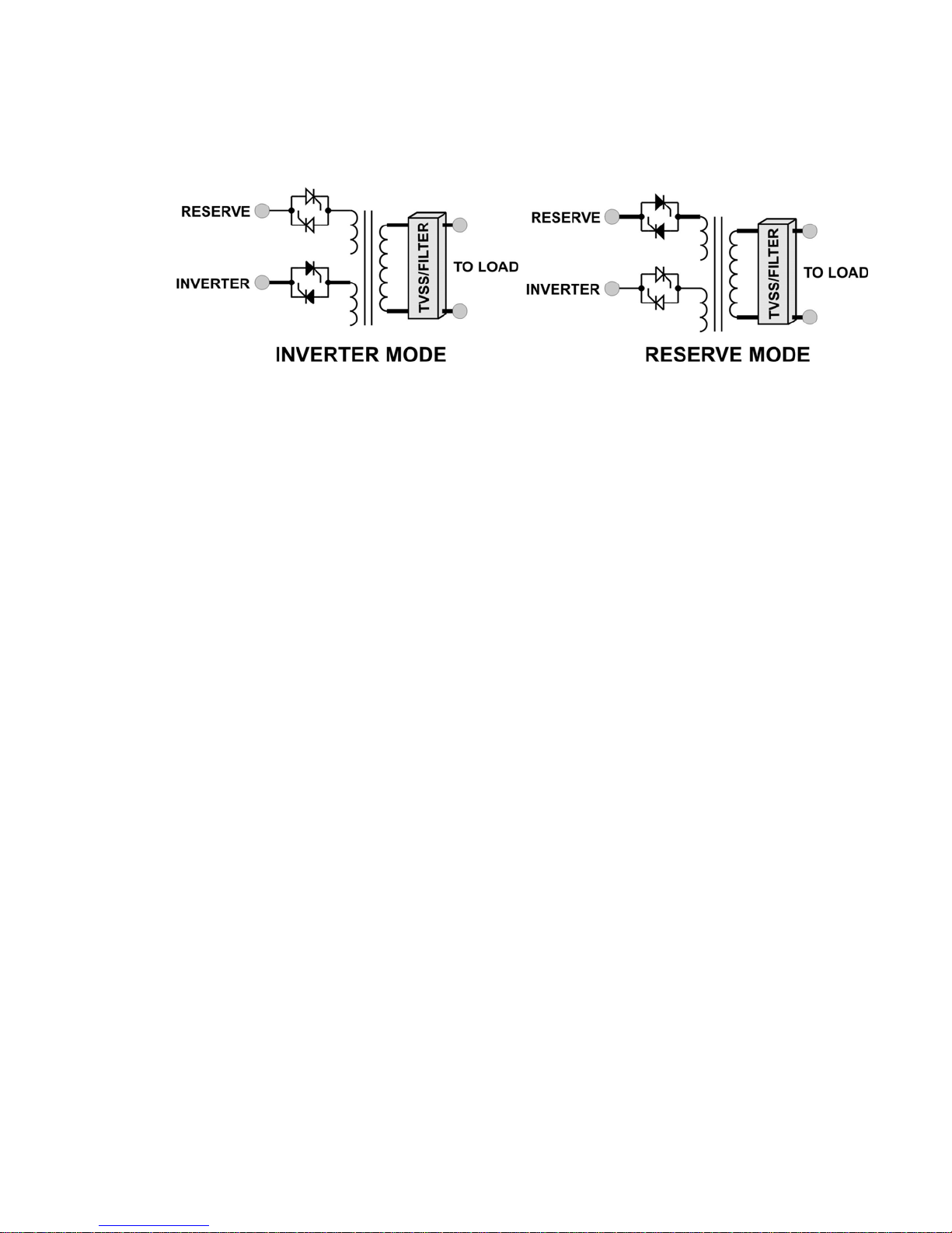
2.9
Static Switch
Figure 2.8
d
inverter without interruption of power to the load.
Detection circuitry is included in the control circuit to achieve “0” dead time
transfer. Additional detection is employed to control the static switch transfer.
Dead Short: If a dead short circuit was to occur under normal mode operation,
reserve breaker.
Overload condition: The ELI will transfer the load to reserve (utility) path. The
inverter
removed and inverter is allowed to reset.
The static switch will only be activated if the input levels are within parameters to
exchange is smooth.
Manual Bypass Switch
will be transferred to reserve (utility) power.
2.10
10
Static Bypass
The static switch is composed of two pairs of back to back naturally commutate
SCR’s, which moves the load from inverter to reserve (utility) or from reserve to
the ELI would detect the short circuit and immediately stop the inverter until the
problem has been rectified. Due to the large amount of current a dead short
requires, the static switch will not transfer to reserve preventing the tripping of the
static switch is designed to handle 110% of the capacity of the system, but will
switch to the reserve path if the overload continues for the specified length of
time. The load will be operational, but in the event of a utility failure the
has been shutdown therefore no battery time is available until the overload is
ensure the load is only supplied with acceptable power to protect against
damage that may be caused t o the critical load. T he system performs numerous
checks on the transfer from inverter to bypass and visa versa to ensure the
The manual bypass switch is a function of Tycor UPS ELI’s that is open under
normal operation, and closed for service. All power supplied to the ELI should be
disconnected before service begins. The manual bypass is switched seamlessly
to supply utility AC power to the loads during ELI servicing. If the bypass breaker
is closed (by mistake) under normal operations, the inverter will stop and the load
M4102 Ty-Borealis 8-48KW Operators Manual v1.0 2013-08-14
Page 21

The inverter cannot be turned on when the maintenance bypass breaker is in the
closed position.
(The operation of the manual bypass breaker is explained later in this manual)
11
M4102 Ty-Borealis 8-48KW Operators Manual v1.0 2013-08-14
Page 22

12 Pulse Rectifier
Driver
Features
Figure 3.1
Block Diagram for Component and Feature Layout
12
6 Pulse Rectifier
Optional Communication
3 Inter-PCB Diagram
Rectifier
Driver
Rectifier
Driver
LCD
Switch
LED
Dry
Contact
Rectifier
Control
Rectifier
Control
Display
Call
Service
Power Supply
Controller
Remote Control
Panel
PC
Communications
SNMP (Web)
Monitoring
Battery Monitoring
Batt
Relay
SS Drive
R Phase
S Phase
T Phase
Inverter
Driver
Inverter
Driver
Inverter
M4102 Ty-Borealis 8-48KW Operators Manual v1.0 2013-08-14
Page 23
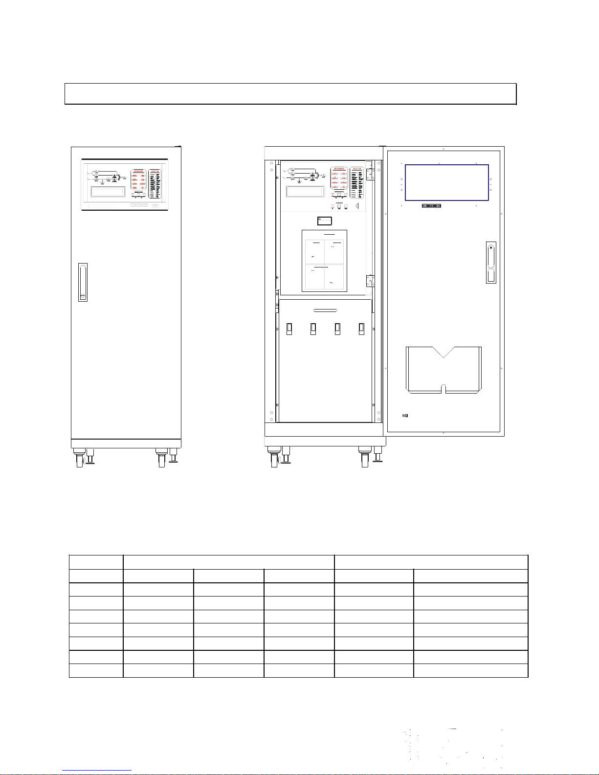
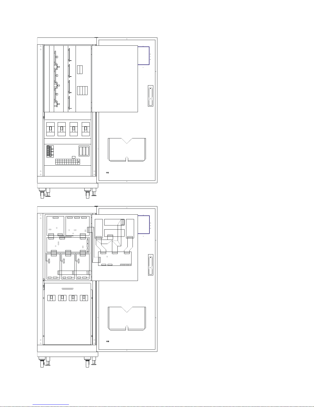
Figure 4.1
with
Door Closed
Figure 4.2
Front view of system with Door Open
13
ELI Rating
Dimensions
Weight
breaker.P3.
pressing
r
e
Man
B
In
Clo se th e
4 Physical Topology
! WARNING
Startup
Proc
edure
1. Close the
INPUTbrea
ke r.P2.
Close the
RESERVE
1. Tu rn o ff
th e IN
VERTERm
INPUT RECTIFIER RESERVE BYPASS
Invert
er to
Manu
al
Bypa
ss P
Da
nge ro
us AC
&
Op erating Proc ed ure
DCPHI
Wa rn ing: Fo r In
G H
VOLT
AGE !
1. Turn off th
e IN
VERTERm o
du le byP
oced ur
ypasst o
ve rterP
1.
lose all fuse s
behind t he c
ontro lP mo
du le door.P2.
Shut
down
Proc
edure
ual
Front view of system
(KW) W (Width) D (Depth) H (Height) ELI Floor Loading
8 559mm (22") 815mm (32.0") 1,600mm (63.0") 380kg (838lbs) 864 kg/sq.m (177 lbs/sq.ft.)
12 559mm (22") 815mm (32.0") 1,600mm (63.0") 415kg (915lbs) 943 kg/sq.m (193 lbs/sq.ft)
16 559mm (22") 815mm (32.0") 1,600mm (63.0") 450kg (992lbs) 1,023 kg/sq.m (210 lbs/sq.ft)
24 559mm (22") 815mm (32.0") 1,600mm (63.0") 580kg (1,279lbs) 1,318 kg/sq.m (270 lbs/sq.ft.)
32 559mm (22") 815mm (32.0") 1,600mm (63.0") 650kg (1,433lbs) 1,477 kg/sq.m (303 lbs/sq.ft.)
40 559mm (22") 815mm (32.0") 1,600mm (63.0") 710kg (1,565lbs) 1,614 kg/sq.m (330 lbs/sq.ft)
48 1,100mm (43.25") 815mm (32.0") 1,600mm (63.0") 920kg (2,024lbs) 1,672 kg/sq.m (207 lbs.sq.ft.)
M4102 Ty-Borealis 8-48KW Operators Manual v1.0 2013-08-14
Page 24
C
C
Figure 4.3
Open, PCB Module fully open and
terminal strip cover off
IN IR IS IT OR OS OT ON B+ B-
CNC
CNB
CNB
CNB
CNC
CNA
CNA
CNA
CNR
CNR
CNR
REWBL
CNT3 CNT4
Figure 4.4
Door
open
14
CNR
T
CNT
CNT
CNT
1 CNT
T
1 CNA1
CNA5
5 CNB
6
T
L
O
T
R
HES
R
PANEL
TO S.S.
TE
CNT2
CNT2
CONTROL
CNT2
CONTROL
RS232
INV.
CNT3 CNT4
AP
C
LOWER
A
C
P
S
SS O/P O/P
PS R
O/P
S T
Front view of system with Door
MAIN CONTROL
INVERTER
PHASE
3B
POWER
SUPPL
G
G R
3A
CN
3T
INVERTER
PHASE
WARNI
NG
R
CNB
LED
PANEL
CNB6
& SWITC
R
G
3T
CN
TO
3C
REC
ER
I FI
C
N
R G
O
EC.
MODULE
R
R
R
R
3T
INVERTER
PHASE
CONTROL
(R PHASE)
M4102 Ty-Borealis 8-48KW Operators Manual v1.0 2013-08-14
LCD PANEL
STATU
S LED
PANEL
TIONS
INTERFA
CE
& BEEPE
3R
RFACE
MIMIC
R
COMMUNICA
Front view of system with
Open and PCB Module door
Page 25
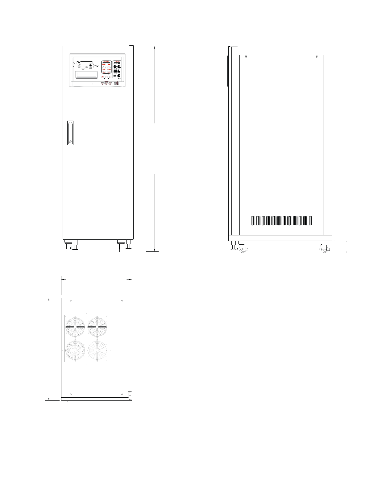
559mm [22”]
Figure 4.5
Front, Side & Top Views of the System
15
1600mm
[63"]
95mm
[3
3/4"]
815mm [32”]
M4102 Ty-Borealis 8-48KW Operators Manual v1.0 2013-08-14
Page 26
5.1
Site & Environmental Conditions
provide optimal back-up time depending on the capacity connected battery bank.
Usually the life expectancy of the ELI is 8 to 10 years. The optimal life
environment.
The following precautions and recommendations should be checked when
considering the site and environment for the ELI:
a. The ELI should be located in a place with adequate ventilation (refer to the
specification of the heat dissipation of the ELI). Should the ELI be installed in a
sealed room,
provided.
care
must
be
taken
to
ensure
adequate heat
evacuation
is
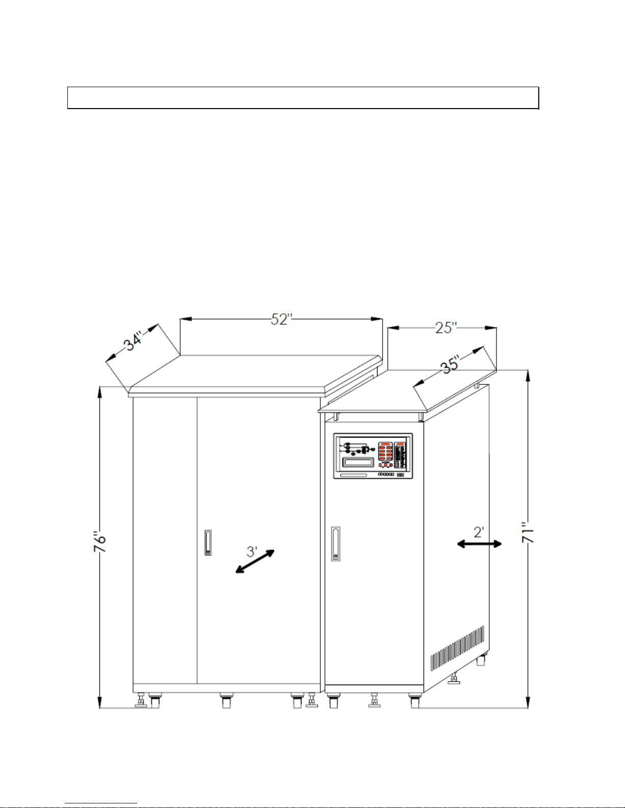
Figure 5.1
Minimum Spacing Requirements
16
5 Installation
The designed function of the ELI is to provide a safe, clean and independent
electrical supply f ree f rom random variations, disturbances or int erruptions of the
utility mains. The ELI will provide a constant power source, which is regulated in
both voltage and frequency. When the utility mains are not available, the ELI will
expectancy of the ELI can be achieved by careful consideration of the site and
M4102 Ty-Borealis 8-48KW Operators Manual v1.0 2013-08-14
Page 27

b.
Void space is not required on all sides of the ELI system, but adequate
space, a minimum of 1m (3’), should be allowed for the door to open. Adequate
Leave a minimum of 2 feet on right hand side of ELI.
c. The battery banks require access to front only.
d.
Do not place any objects on the top of the ELI that might obscure the
ventilation. Do not place the ELI near any heat source, or machinery, which may
that will produce corrosive substances or vapor.
e.
Do not place the ELI below the shower of a fire extinguishing system
(optional drip shield available). Abnormal conditions of the ELI should be
protected by a cutoff from the power supply.
f.
The user is required to guarantee the temperature and humidity values of the
site into which the ELI will be installed meet the required and published
and
humidity 0 to 95% non-condensing.
g.
The floor loading capacity should be sufficient to endure the weight of the
ELI. Four right-angled steel feet attached restrainers are included with the ELI
vehicles, or tanker.) The locations and layout of the restrainers are shown below.
h.
Walls, ceilings, floors or anything near to the ELI should be constructed of
non-combustible materials. A portable fire extinguisher should be accessible
nearby.
i. Avoid accumulating litter or trash of any sort in or around the ELI system.
powder and/or filings.
j.
Access to the ELI room should be limited to operation and maintenance
personnel. The doors should be kept locked and the keys should be available
only to authorized personnel.
k.
Personnel who operate or maintain the ELI system should be proficient in
normal and emergency operational procedures. New personnel should be
trained and qualified prior to operation of the equipment.
l.
Although the ELI has passed the international EMC tests, it is not
recommended to install the ELI near to any equipment that is susceptible to
17
space, a minimum of 60cm (2’) [recommended 1m (3’)], should also be allowed
at the top of the ELI system to allow for proper heat dissipation and ventilated
through the top openings (optional ventilation booth is available upon request).
produce metallic particles, dust or powder. Do not place the ELI near equipment
manufacturer specifications. The ELI should be installed within the range allowed
by these specifications. The ELI is capable of continuous normal operation within
a temperature range of 0°C (32°F) to 40°C (104°F). For optimal performance
reliability the recommended environment temperature is best at 25°C, with
system, which should be inserted into the floor for securing the ELI system, when
the location has the potential to experience vibrations. (e.g.: earthquake, moving
The floor area surrounding the ELI should be kept clean, free from metallic
M4102 Ty-Borealis 8-48KW Operators Manual v1.0 2013-08-14
Page 28

electro-magnetic interference, such as computer systems, monitors, radios etc.
m.
The system should be connected to the emergency generator, if available.
n.
The system, when installed in a sprinkler-equipped room, must have a
sprinkler guard installed.
5.2
Cable Selection
The cabling of the ELI system has to be sized according to the ELI power rating.
Sizing of circuit breakers, fuses and cables for input utility, output load and battery
must meet the requirements of local and national electrical codes.
Refer to Section 10 for technical specifications.
18
WARNING
Inadequate cable size and over sized breakers can increase the risk of fire or damage
connection cables and internal components.
M4102 Ty-Borealis 8-48KW Operators Manual v1.0 2013-08-14
Page 29
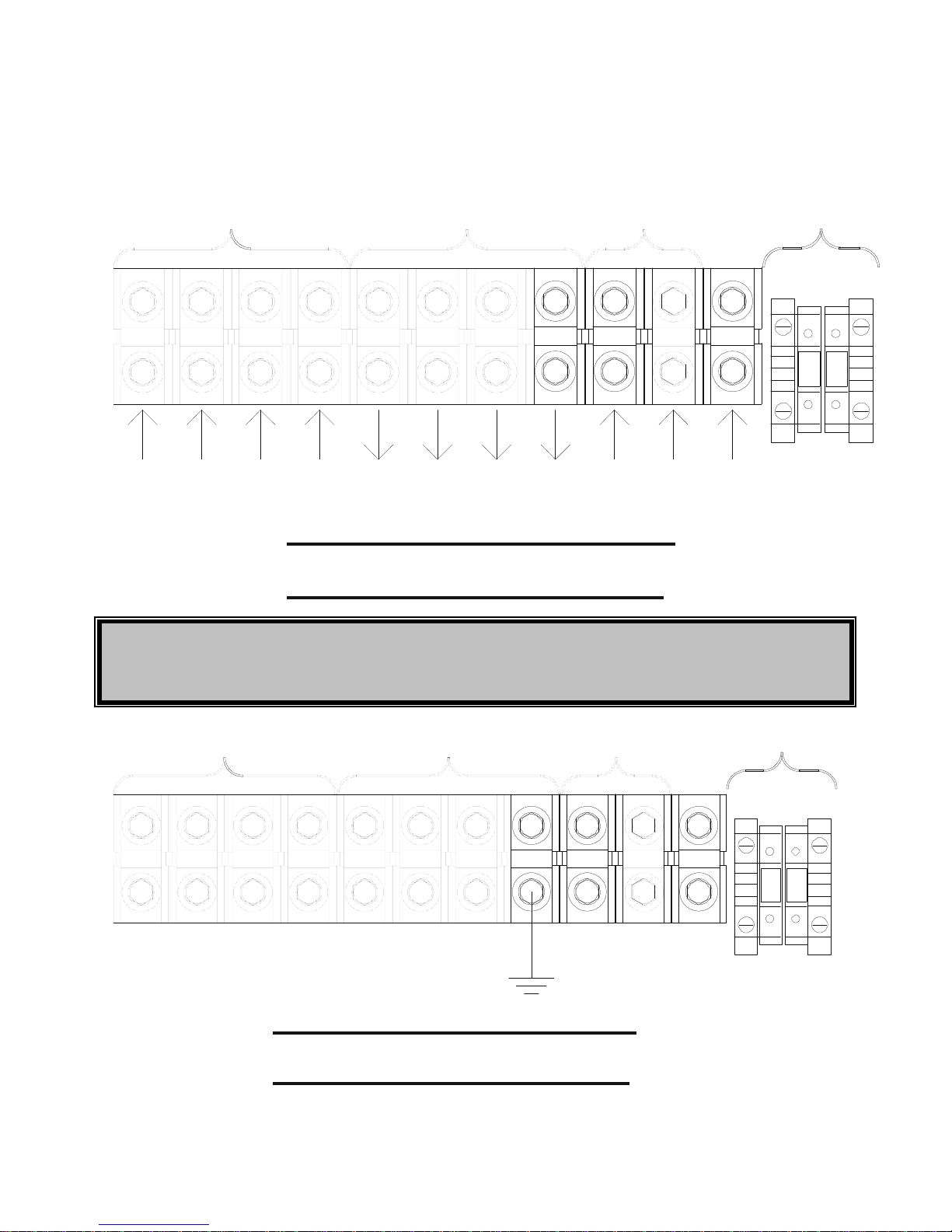
5.3 Terminal Strip Connections
FIRE ALARM
CONNECTION
RECTIFIER & RESERVE
INPUT
ELI
OUTPUT
BATTERY
INPUT
LINE
RED
LINE
RED
LINE
BLACK
LINE
BLUE
N
BAT
BLACK
N
LINE
BLACK
LINE
BLUE
BAT
RED
G
WHITE
WHITE GREEN
3 PHASE INPUT / 3 PHASE OUTPUT
TE RMINAL WITH SINGLE SOURCE
FIREALARM
CONNECTION
ELI
OUTPUT
BATTERY
INPUT
RECTIFIER& RESERVE
INPUT
3 PHASE INPUT/ 3 PHASE OUTPUT
TE RMINAL WITH SINGLE SOURCE
19
ON
B+
G
*
ON
B+
G
IN
IR
1
IS
2
IT
3
OR
1
OS
2
OT
3
+
B-
-
* CAUTION: REMOVE THE NEUTRAL BONDING JUMPER IF ELI IS CONNECTED TO AN
EXTERNAL BYPASS SYSTEM.
IN
IR
IS
IT
OR
M4102 Ty-Borealis 8-48KW Operators Manual v1.0 2013-08-14
OT
OS
B-
Page 30
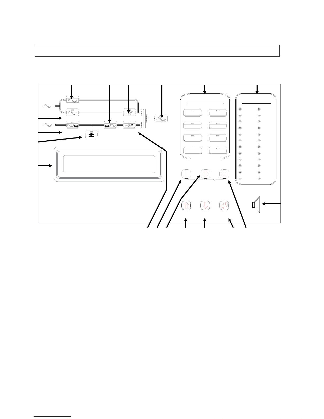
E I K L B C F G H A D
J
P Q
M
N O R
Figure 6.1
Front Panel Display
The front panel is located behind the glass window on the front of the ELI system. It
el
explained below:
A: LCD display- Real time status, data and historical events are displayed on the LCD.
be
and
will light up again when one of the up/down/enter keys are pushed.
20
INVERTER ON
RESERVE
RESERVE
OUTPUT
SHORTCIRCUIT
BATTERYLOW
RECTIFI
VERTER
INVERTER
INV SHUTDOWN SHUTDOWN
HIGH DC BUSS
RECTIFIER
INV OVERLOAD RECTIFIER
INV SHUTDOWN HIGH DC
70% LOAD
INVERTER CONTROLS
110% LOA D
TEST
125% LOA D
EMERGENCY
150% LOA D
ON OFF
IN
6 Front Panel
BYPASS
WARNING
RECT AC FAIL HIGH DC
OVERLOAD FAULT
INV STATIC
STATUS
BOOST
COMM.
LCD CONTROLS
UP
DOWN ENTER
displays the real time information and status of the ELI and battery system. It also
provides for user interface for controlling and setting the ELI operating status. This pan
also allows the user to operate and monitor the system with ease. The panel is
The ELI parameters, real time clock, inverter, and buzzer can also
set through this LCD. The LCD is back lit by LED’s for a sharper
display, but in order to lengthen the LED’s life time, the LED will
automatically shut off 3 minutes after a key has been pressed,
M4102 Ty-Borealis 8-48KW Operators Manual v1.0 2013-08-14
Page 31

B:
Warning
LED’s-When an abnormal condition occurs, these LED’s will illuminate
described below:
•
RECT AC FAIL – when the supply to the rectifier is outside of the
(refer to C: Status LED’s).
•
RES AC FAIL – supply to the reserve is outside of the operating
emergency stop (refer to C: Status LED’s).
•
•
•
• •
•
C: Status LED’s-
24 LED’s represent the real-time information regarding the status of
shooting abnormal conditions. The 24 LED’s represent the following:
•
•
INVERTER ON – inverter is running.
supplying
inverter is operating.
• • •
21
allowing the user to identify the fault. This will also allow the service
personnel the ability to troubleshoot the system. These LED’s are
operating parameters. This not only applies to voltage range but also
when phase rotation is incorrect or the rectifier has been shutdown
parameters. Supply voltage or frequency out of range (refer to C:
Status LED’s).
FUSE/TEMP – inverter has shutdown due to inverter fuse open or
heat sink temperature above operating parameters.
OVERLOAD – an overload condition has occurred on the output.
HIGH DC – this LED will be lit as long as the DC voltage exceeds
430VDC.
BAT LOW – this LED will be lit as long as the DC voltage is lower
than 320VDC.
BAT LOW STOP – the LED will be lit as long as the DC voltage is
lower than 295VDC. The inverter will not activate until the DC voltage
is above this level.
FAULT – the inverter has shutdown because an abnormal condition
has occurred. Possible conditions include overload, short circuit, high
DC shutdown, fuse/over temperature, bypass breaker on or
the ELI system. These LED’s will aid in diagnosing and trouble
INV STATIC SWITCH ON – inverter static switch is active.
•
OUTPUT SHORT CIRCUIT – ELI output is in a short circuit state.
•
FUSE/TEMP INV SHUTDOWN – inverter has shutdown due to
inverter fuse open or heat sink temperature above operating
parameters.
INVERTER FAIL INV SHUTDOWN – inverter has shutdown due to
inverter output voltage below tolerances.
BYPASS ON INV SHUTDOWN – inverter has shutdown because the
bypass breaker has been activated while the inverter is
power to the load.
HIGH DC BUSS INV SHUTDOWN – inverter has shutdown because
the DC Bus voltage is outside of operating parameters while the
M4102 Ty-Borealis 8-48KW Operators Manual v1.0 2013-08-14
Page 32

•
INV OVERLOAD INV SHUTDOWN – inverter has shutdown because
a
• • • • • •
•
• •
•
• • •
• •
22
an overload condition has been detected on the output. The inverter
will automatically restart after the condition has been removed for
period of seven seconds.
70% LOAD – load connected to the output is over 70% of the ELI
rating.
110% LOAD - load connected to the output is over 110% of the ELI
rating.
125% LOAD - load connected to the output is over 125% of the ELI
rating.
150% LOAD - load connected to the output is over 150% of the ELI
rating.
RESERVE AC FAIL – supply voltage to the Reserve is outside of
operating window.
RESERVE FREQ FAIL – supply frequency to the Reserve is outside
of operating window.
BATTERY LOW – the DC bus (or battery) voltage is lower than
320VDC. Low battery shutdown is approaching.
BATTERY LOW SHUTDOWN – the inverter has shutdown because
the DC bus (or battery) voltage is below operating level (lower than
295VDC).
RECTIFIER AC FAIL – supply to rectifier is outside of operating
window.
Ø ROTATION ERROR – supply phase rotation is outside of op er ati ng
window.
RECTIFIER SHUTDOWN – the rectifier has shutdown because the
DC bus voltage has exceeded maximum operating level (over
445VDC). The rectifier will automatically restart 30 seconds this
abnormal condition has been cleared.
RECTIFIER HIGH DC – the DC voltage has exceeded maximum
operating level (over 430VDC). The bus voltage is limited to this
voltage.
BOOST CHARGE – the batteries are being boost charged by the
rectifier.
BATTERY TEST – batteries are being tested.
•
EMERGENCY STOP – the inverter has shutdown because the
emergency stop switch has been activated.
COMM. ACTIVE – blinks when data is being transmitted or received
via the communication port.
M4102 Ty-Borealis 8-48KW Operators Manual v1.0 2013-08-14
Page 33

D: Buzzer outlet: There is a buzzer located behind the LCD Display. The buzzer
will allow for audile notification during an abnormal condition. The buzzer will be
activated under one of the following conditions:
described for your reference.)
(The frequency of the buzzer is also
•
INVERTER IS OVERLOADED
>110%, beep once / 3 seconds
beep continuously
•
BACK-UP
•
•
INVERTER IS SHORT CIRCUITED
EMERGENCY STOP
The buzzer will beep once every time the inverter is switched on or
off.
This will allow for the user to be sure the operation was
performed correctly.
E. Bypass LED:
This LED is lit when the maintenance bypass breaker is closed
bypass breaker is closed the inverter will shutdown immediately.
F. Reserve LED:
This LED is lit when the reserve breaker is closed, and the supply is
within operating parameters.
G. Rectifier LED: This LED is lit when the rectifier is operating, the supply is within
voltage is within operating parameters.
H. Battery LED:
This LED is lit while the ELI is in back-up mode. This LED also
ass
battery
pack.
I. Inverter LED:
This LED is lit when the inverter is supplying power to the load.
23
>125%, beep once / second
>150%, beep twice / second
>320VDC, beep once /
3seconds
<320VDC, beep twice /
second
FUSE BROKEN
•
HEAT SINK OVER TEMPERATURE
•
HIGH DC SHUTDOWN
•
BYPASS ON STOP
•
<295VDC, no beeping
beep continuously
beep continuously
beep continuously
beep continuously
beep continuously
leaving the inverter in the off mode. If the inverter is active when the
operating parameters, the rectifier breaker is closed and the DC bus
indicates the results of battery test. If the battery pack does not p
the test, this LED will flash prompting the user to change the
M4102 Ty-Borealis 8-48KW Operators Manual v1.0 2013-08-14
Page 34

J. Inverter Static Switch LED: This LED is lit when the inverter static switch is
for 7sec. after the inverter is switched on.
K. Reserve Static Switch LED: This LED is lit when the reserve static switch is
reserve
Switch LED will never be lit at the same time.
L. Output LED:
This LED is lit when there is AC power present at the output
terminals.
M. Up key:
This is an LCD control key. It moves the cursor one field upward when
when data or parameters of the ELI are being set.
N. Down key:
This is an LCD control key. It moves the cursor one field downward
backward when data or parameters of the ELI are being set.
O. Enter key:
This is an LCD control key. It returns to the previous page, and also
confirms the number/character/item selected.
P. Inverter “On” Switch: This is an inverter control switch. When this switch is pushed
simultaneously with the control key, the inverter will switch on.
Q. Inverter “Control” Switch:
This is an inverter control switch. When this switch
is pushed in conjunction with the inverter “On” switch the inverter will
f”
switch
to prevent accidental operation of the inverter.
R. Inverter “Off” Switch: This is an inverter control switch. When this switch is pushed
simultaneously with the control switch the inverter will be turned off.
24
operating and the reserve static switch is turned off. When this LED is
on, the load is supplied from the inverter. Usually this LED will stay lit
operating and the inverter static switch is turned off. When this LED
is on, the load is being supplied by the reserve. Since the
static switch and inverter static switch will never operate
simultaneously, the Inv Static Switch On LED and the Reserve Static
items are being selected or changes the number/character forward
when items are being selected or changes the number/character
activate. Similarly, when this switch is pushed with the inverter “Of
switch the inverter will shutdown. This switch acts as a safety
M4102 Ty-Borealis 8-48KW Operators Manual v1.0 2013-08-14
Page 35

After all the cables have been connected and power is present at the input terminal, the
ELI is ready to operate. Before initial start-up, re-check the following:
a.
e.
Make certain there is no foreign material left on, inside or around the ELI
Check that the input voltage matches the ELI’s rated input voltage
7.1
Switch On Procedure (Authorized Trained Personnel Only)
to or with only the batteries connected.
a.
Close the input breaker – Energize the transformer.
b.
Close the reserve breaker – The reserve and output LED on the status
will energize and the internal fans will rotate.
c.
Close the rectifier breaker - The rectifier will automatically start if the AC
voltage is now ready for the inverter and battery bank.
d.
Close the battery breaker holder - A breaker between the battery bank and
ce
the ELI system or within the battery cabinets depending on rating.
e.
Push inverter on switch – To turn on the inverter simultaneously press the
mode.
f.
Check the status panel for correctness as shown in the diagram on the next
%,
the ‘70% LOAD’ LED will also be lit.
25
7 Operation
b.
Ensure all breakers and the battery disconnect switches are opened
c.
Ensure all loads are switched off.
d.
Check that the input frequency matches the ELI’s rated input frequency
These start-up procedures can be performed with the AC utility source connected
panel will light up, indicating the reserve static switch loop is energ ized and
there is power on the output terminals. The power supplies within the ELI
utility power connected is within operating parameters. The DC voltage will
slowly rise (15 – 30 sec.) until the designated voltage is reached. The DC
the ELI is used for safety purposes. The batteries will start charging on
the fuse door or breaker is closed. This fuse holder can be located within
inverter on switch (׀) and the control switch (◄►). The inverter will begin to
function with inverter output within 4 sec. The load will automatically
transfer to the inverter 3 sec. later. The ELI is now operating in normal
page. All warning LED’s on the right hand side are off, two LED’s:
‘INVERTER ON’ and ‘INVERTER STATIC SWITCH’ on the left hand side
should be lit, and the LED’s circle should also be lit. If the load is over 70
M4102 Ty-Borealis 8-48KW Operators Manual v1.0 2013-08-14
Page 36
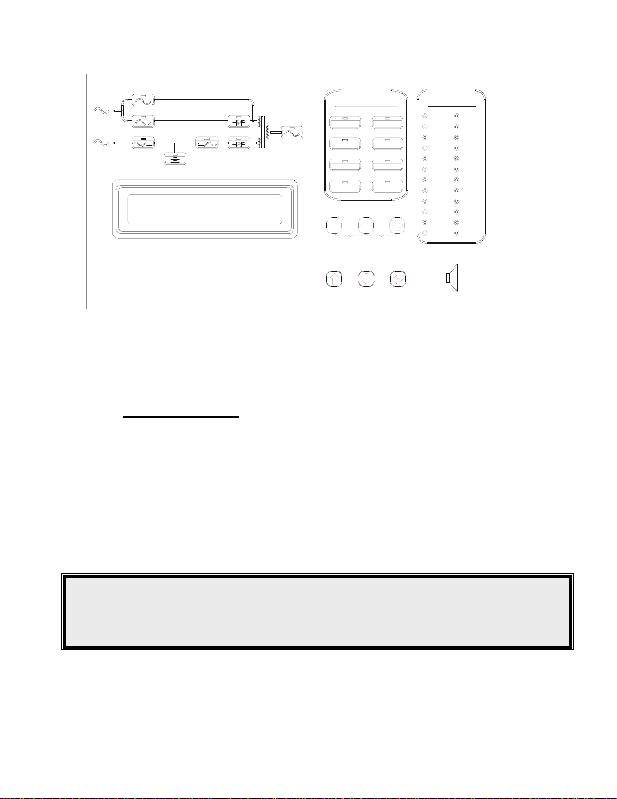
Figure 7.1
Operation
Circles represent LED’s that are on.
7.2
Shutdown Procedure
To completely shutdown the ELI, please follow the following steps.
a.
Switch off the inverter – The inverter can be switched off by simultaneously
The load will be automatically transferred to reserve without interruption.
b.
Open the battery breaker – This will disconnect the batteries from the DC
ELI system or within the battery cabinets.
c.
Open the rectifier breaker – Opening the rectifier breaker will remove the
reaches a save level of approximately 20VDC.
d.
Open the reserve breaker – Before opening the reserve breaker you must
RESERVE (UTILITY) BREAKER IS OPENED.
26
RESERVE
INVSTATIC
RESERVE
RECTIFIER
INVERTER
INVERTER
INV SHUTDOWN SHUTDOWN
INV OVERLOAD RECTIFIER
70% LOAD
BOOST
INVERTER CONTROLS
110% LOAD
EMERGENCY
150% LOAD
BYPASS
WARNING
RECTAC FAIL HIGH DC
OVERLOAD FAULT
ON OFF
LCD CONTROLS
UP
DOWN ENTER
Status Panel Display Under Normal
STATUS
INVERTER ON
INV SHUTDOWN ERROR
TEST
COMM.
pressing the inverter off switch (O) and the inverter control switch (◄►).
bus and the ELI no longer has back-up available. This is located within the
power source from the DC bus. The DC bus will start to drop slowly until it
WARNING!
Completing the next step will turn off the power to the loads.
Make sure all loads have been turned off before proceeding or the external wraparound bypass has been initiated.
make sure there is no critical load connected to the ELI that requires power.
NO OUTPUT POWER WILL BE SUPPLIED FROM THE ELI ONCE THE
M4102 Ty-Borealis 8-48KW Operators Manual v1.0 2013-08-14
Page 37
e. Open the input breaker – transformers will de-energize.
f. Now that all power has been cut off within the ELI system. All LED’s, displays
and fans should be off.
7.3
From Inverter To Manual Bypass Procedure
The following procedures will allow the service personnel to switch the ELI
loads.
a.
Switch off the inverter – The inverter can be switched off by simultaneously
).
interruption.
b.
Open the battery breaker – This will disconnect the batteries from the DC
ELI system or within the battery cabinets.
c.
Open the rectifier breaker – Opening the rectifier breaker will take the
to
20VDC).
d.
Close the bypass breaker – The reserve breaker and reserve static switch
because the impedance of the bypass loop is lower.
e.
Open the reserve breaker – You can now open the reserve breaker to cut
off any power within the ELI electronics.
NOTE: To place the unit into Maintenance Bypass mode the fuse holders behind
the control module (where all control PCB’s are stored) must be opened.
The system is now in Manual Bypass mode (or Maintenance Bypass mode).
27
several terminals on the PCB’s.
CAUTION!
Terminal strip and breakers may still be energized if the main input breaker feeding
the ELI system is not turned off or open.
system to maintenance bypass mode without interrupting the output power to the
pressing the inverter off switch (O) and the inverter control switch (◄►
The load will be automatically transferred to reserve (utility) supply without
bus and the ELI no longer has back-up available. This is located within the
power source away from the DC bus; therefore, the DC bus will start
drop slowly. After 5 min., the DC bus will drop to a safe level (approx.
are still conducting. When the maintenance bypass break er is closed,
power will flow through the bypass loop instead of the reserve loop
CAUTION!
If the fuse holders have not been opened, power is still present and fans will be
turning. If the fuse holders are open power is still present at the terminal strip and
M4102 Ty-Borealis 8-48KW Operators Manual v1.0 2013-08-14
Page 38

7.4
From Manual Bypass to Inverter Procedure
After the maintenance procedures and testing are complete you will need to
power to the loads. The following procedures need to be followed.
a.
Close all fuse holders – ensure all fuse holders behind the control module
are closed. Fans will start spinning.
b.
Close the reserve breaker – Wait 15 seconds for the reserve and output
supplies within the ELI will also energized and the internal fans will rotate.
c.
Open the bypass breaker – The inverter cannot be switched on when the
reserve
interrupted.
d.
Close the rectifier breaker - The rectifier initiates automatically if the AC
voltage is now ready for the inverter and battery cabinets.
g.
Close the battery breaker - A fuse holder is employed from the battery to
breaker is closed. The breaker can be located within the battery cabinets.
h.
Push inverter on switch – To turn on the inverter simultaneously press the
in normal mode.
e.
Check the status panel is correct, as shown in the diagram on the previous
%,
the ‘70% LOAD’ LED will also be lit.
7.5
Manual Battery Test
ungrounded conductors. This process will simulate a failure of utility supply.
7.6
Battery Condition Test
information.
28
restore the ELI back to its normal mode of operation without interrupting the
LED on the status panel to light up, indicating the reserve static switch loop
is energized and there is power on the output terminals. The power
maintenance bypass breaker is closed (because the CPU will sense the
breaker and prevent the inverter from connecting directly to the AC source).
The reserve breaker is already closed so power goes through the
loop if the bypass breaker is open. AC power at the output will not be
utility power connected is with in operating parameters. The DC voltage will
slowly rise (15 – 30 sec.) until the designated voltage is reached. The DC
the DC bus for safety purposes. The batteries will start charging once the
inverter on switch (׀) and the control switch (◄►). The inverter will start
working and the inverter output will be established in 4 sec. The load will
automatically transfer to the inverter 3 sec. later. The ELI is now operating
page. All warning LED’s on the right hand side are off, two LED’s:
‘INVERTER ON’ and ‘INVERTER STATIC SWITCH’ on the left hand side
should be lit, and the LED’s circle should also be lit. If the load is over 70
To initiate a manual battery test turn off the input breaker to disconnect all
To be performed by service personnel. Consult service manual for more
M4102 Ty-Borealis 8-48KW Operators Manual v1.0 2013-08-14
Page 39

The LCD displays Real Time information as to the status and operation characteristics of
enabled (i.e. the default screen).
8.1 Menu 0 – Main Menu
Figure 8.1
Main Menu Display
The first row will display the greeting content set by the factory. The model no.
row. The third row will display the kVA rating, input rating and output rating of the UPS.
The serial no. is set by the factory for the convenience of maintenance personnel who
29
M O D E L : X X X X I I I
S / N : 3 4 5 6 7 8 9
0 I D : 0 1
5 0 K V A I : 1 2 0 2 0 8
V 6 0 H
Z O : 1 2 0 2 0 8
V 6 0 H
Z
2 0 0
7 0
1 0
1
T U E
0 8 : 0 0 A
M
8 The LCD Display
the UPS system and battery banks. In order to make the display sharp and readable, the
LCD is back-lit by LED’s. To prolong the life of the LED, the CPU will cut off the power of
the LED 3 minutes after the last key has been pressed. The backlight will illuminate
whenever a key has been pressed. This screen will pop up once the system power is
(MODEL), serial no. (S/N), and the identification no. (ID) are displayed in the second
may need to refer to the serial number for the correct spare parts and testing
procedures. The identification no. is set only when multiple UPS systems are connect ed
in parallel. Each UPS must have a unique number to identify itself, and will be set by a
factory trained technician after installation. The YEAR/MONTH/DATE, DAY OF THE
WEEK, HOUR, MINUTE and AM/PM from the real time clock inside the UPS are
displayed in the fourth row for user’s reference and for stamping the date and time in the
historical data when an abnormal conditions occurs. By pressing one of the UP(↑),
DOWN(↓) or ENTER(↵) keys, the LCD will change to another screen.
M4102 Ty-Borealis 8-48KW Operators Manual v1.0 2013-08-14
Page 40

8.2
Menu 1 – Select Menu
Figure 8.2
user for a password. Contact service provider for more information.
8.3 Menu 2 – Status Warning Menu
Figure 8.3
Status Warning Menu Display
The Status/Warning menu is accessed through MENU 1 by selecting STATUS
conditions occur and the title < WARNING > will then change to < FAULT >.
For example, if a short circuit has occurred, this screen will display as follows:
Figure 8.4
Warning Status Display with Fault Condition
30
S T A T U
S
F A U L
T
R E C T I F I E R = O N
S H O R
T
C I R
C U I T
I N V E R T E R = O F
F
L O A
D
O
N
I N V E R T E
R
S T A T U
S
W A R N I N
G
R E C T I F I E R = O N
I N V E R T E R = O
N
L O A
D
O
N
I N V E R T E
R
S
E L E C T M E N
U
S T A
T U S W A R N I N G F
A
U L T
P
A
R
A
M
E
T
E
R S
E
T
R E A
L T I M
E D A T
A
H I S
T O R I C
A
L D A T
A
E X I
T
Select Menu Display
MENU 1 is reached by pressing any button on the opening screen and is also the default
menu. From this menu the personnel can select STATUS WARNING FAULT, REAL TIME
DATA, HISTORICAL DATA and PARAMETER SET menus. To select an option move the
cursor (→) by pressing the UP (↑) key, or the DOWN (↓) key. Selections are confirmed by
pressing the ENTER (↵) key. The user will be sent to the menu the cursor is pointing to. If
the item ‘PARAMETER SET’ is selected, the LCD will jump into a screen that will prompt the
WARNING FAULT. The left-hand side of this menu shows the real time status of the
rectifier, inverter and static switch, while the right hand side shows the warning or fault
condition if any. Under normal condition, the LCD display should be exactly the same as
the figure shown above. When abnormal conditions occur it will be shown under the title
< WARNING >, but this will be overridden by a “fault” message if more serious abnormal
M4102 Ty-Borealis 8-48KW Operators Manual v1.0 2013-08-14
Page 41

The inverter will automatically shut off under a short circuit fault. The CPU is designed to
power present)
Listed below are all the warning conditions that can be displayed (they are arranged in
order of priority, starting with the highest priority):
1
st
row:
BYPASS ON – Output is being supplied by the reserve
reserve has been disabled until error is corrected
2
nd
row:
170% OVERLOAD – over 170% maximum capacity for the ELI system.
system.
system.
110% OVERLOAD – over 110% maximum capacity for the ELI system.
3
rd
row:
BATTERY LOW STOP – Battery have been exhausted.
BATTERY TESTING – performing test on the batteries.
Listed below are all the fault conditions that can be displayed:
1
st
row:
2
row:
HIGH DC SHUTDOWN – DC Bus voltage out of operating range.
SHORT CIRCUIT! – a short circuit condition has occurred on the output.
INVERTER ABNORMAL – inverter is not operating within specified
parameters.
3
rd
row:
mode.
BYPASS ON SHUTDOWN – inverter failure, system operating in bypass
MENU 1, when ENTER (↵) is pressed.
31
detect short circuits and in order to avoid unnecessary tripping of the reserve (utility
supply) breaker, the static switch will remain open or inactive. (There will be no output
RECT AC FAIL – AC utility source failure
RECTIFIER PHASE ERROR – AC utility phase loss or one phase out of
operating parameters
RESERVE FREQ. ERROR – AC utility frequency is out of parameters and
150% OVERLOAD – over 150% maximum capacity for the ELI
125% OVERLOAD – over 125% maximum capacity for the ELI
BATTERY LOW – Batteries have passed the low voltage level and will soon
be exhausted.
BATTERY BAD – One or more cells have tested faulty.
BATTERY GND FAULT – Battery cabinet not grounded properly.
nd
FUSE/OVERHEAT – a fuse has blown or the system has shutdown due to
overheating.
OVERLOAD SHUTDOWN – system has exceeded the overload limit beyond
the operating window.
EMERGENCY STOP – user has activated the emergency stop feature.
The UP (↑) or DOWN (↓) key has no function in this menu. The screen will go back to
M4102 Ty-Borealis 8-48KW Operators Manual v1.0 2013-08-14
Page 42

8.4
Menu 3 – Real Time Data Menu
Figure 8.5
to
RESERVE
the
Selecting the ‘EXIT’ option (blinking instead of pointed by cursor) will return you to
MENU 1.
Rectifier Data Menu
Figure 8.6
Rectifier Data Menu Display
This menu is reached by selecting RECTIFIER DATA on MENU 3. The information
VOLTAGE on delta (≥) configured systems.
MENU 3 when the ENTER (↵) key is pressed.
Reserve Data Menu
Figure 8.7
Reserve Data Menu Display
32
<
R E S E R V E D A T
A >
R E S E R V E F R E Q U E N C Y = X
X H
Z
R - N = X X X V a c
S - N = X X X V a c
T - N = X X X V a c
R E C T I F I E R
D A T A
>
R E C T I F I E R
F
R E Q U E N C Y = X X
H
Z
R - N = X X
X
V a
c
S - N = X X
X
V a
c
T - N = X X
X
V a
c
R E A
L
T I M
E
D A T
A
R E C T I F I E R
D A T
A
O T H E
R
D A T A
R E S E R V
E
D A T
A
O U T P U
T
D A T
A
E X I
T
Real Time Data Menu Display
MENU 3 is reached by selecting REAL TIME DATA on MENU 1. The cursor(→) is used
select what type of real time data the user would like to view, RECTIFIER DATA,
DATA, OUTPUT DATA and OTHER DATA. To select one of the different menu options
move the cursor(→) until it is pointing at the correct selection, by press the UP (↑) key or
DOWN (↓) key. To confirm and select the menu option press the ENTER (↵) key.
provided on this menu is the real time readings of the rectifier input; RECTIFIER
FREQUENCY, R-N/S-N/T-N VOLTAGE for wye (Y) configured systems or R- S/S-T/T-R
The UP (↑) or DOWN (↓) key has no function in this menu. The screen will return to
M4102 Ty-Borealis 8-48KW Operators Manual v1.0 2013-08-14
Page 43

This menu is reached by selecting RESERVE DATA on MENU 3. The information
VOLTAGE on delta (≥) configured systems.
The UP (↑) or DOWN (↓) key has no function in this menu. The screen will return to
MENU 3 when the ENTER (↵) key is pressed.
Output Data Menu
Figure 8.8
configured systems.
MENU 3 when the ENTER (↵) key is pressed.
Other Data Menu
Figure 8.9
VOLTAGE, CHARGE OR DISCHARGE CURRENT.
When the ELI system is operating in normal mode the last line will read CHARGE
CURRENT and will represent the amount of current being supplied to the batteries.
33
O T H E R
D A T
A
T E M P E R A T U R E = X
X
C
D
C
V O L T A G E = X X
X
V d
c
C H A R G E
C U R R E N T = X X X A
O U T P
U T
D A T A
O U T P
U T
F R E Q
U E N C Y = X X
H
Z
L O A D : R = X X
X
%
S = X X
X
%
T = X X
X
%
R - N = X X
X
V a
c
S - N = X X
X
V a
c
T - N = X X
X
V a
c
provided on this menu is the real time readings of the reserve input; RESERVE
FREQUENCY, R-N/S-N/T-N VOLTAGE for wye (Y) configured systems or R- S/S-T/T-R
Output Data Menu Display
This menu is reached by selecting OUTPUT DATA on MENU 3. The information provided on
this menu is the real time readings of the inverter or reserve output (depending on what
mode the system is in); OUTPUT FREQUENCY, LOAD % OF R/S/T, OUTPUT R-N/S-N/T-N
VOLTAGE for wye (Y) configured systems or R- S/S-T/T-R VOLTAGE on delta (∆)
The UP (↑) or DOWN (↓) key has no function in this menu. The screen will return to
Other Data Menu Display
This menu is reached by selecting OTHER DATA on MENU 3. The information provided
on this menu is the real time readings of the ELI system; TEMPERATURE, DC
M4102 Ty-Borealis 8-48KW Operators Manual v1.0 2013-08-14
Page 44

When the system changes to back-up mode the last line will change to DISCHARGE
batteries (figure below).
Figure 8.10
Other Data Menu Display when system in Back-up
3 when the ENTER (↵) key is pressed.
8.5
Menu 4 – Historical Event Menu
Figure 8.11
ach
or maintenance personnel to trace back that occurrence. A maximum of 77 records can
be
stored
in
one
EEPROM.
This
can
be
increased to 154 records with the addition of a second EEPROM. These records are
until they’re overwritten by the 78
(or the 155th) events.
The three most recent records are displayed at one time on the view screen. The
nd
34
D A T
E T I M
E E V E N T
S >
R U N : 2 1 Y R 0 3 M
O
2 0 0 2 \ 0 3 \ 2
9
0 9 : 3 2
2 0 0 2 \ 1 1 \ 0
1
2 2 : 1 5
2 0 0 3 \ 0 3 \ 1
0
1 5 : 4 7
O T H E R
D A T
A
T E M P E R A T U R E = X
X
C
D
C
V O L T A G E = X X
X
V d
c
D I S C H A R G E
C U R R E N T = X X X A
CURRENT displaying how much current is being supplied to the inverter from the
The UP (↑) or DOWN (↓) key has no function in this menu. The screen will return to MENU
Historical Event Menu Display
MENU 4 is reached by selecting HISTORICAL DATA on MENU 1. All abnormal events
are stored on the EEPROM and viewed through this menu based on the time e
event occurred. The record display starts with the date and time stamp allowing the user
hard coded onto the EEPROM and will not be erased by cutting off the power supply or
during a complete shutdown of the ELI, i.e. they will be kept in the EEPROM forever
th
displayed records will move one record upward when the UP (↑) key is pressed, a
move one record downward when the DOWN (↓) key is pressed.
M4102 Ty-Borealis 8-48KW Operators Manual v1.0 2013-08-14
Page 45

Below is a list of the abnormal conditions that are stored and can be displayed:
HIGH DC SHUTDOWN / SHORT CIRCUIT! / FUSE/OVERHEAT / OVERLOAD
SHUTDOWN
The display in the top right corner of the screen is the ELI installation time displayed in
To return to MENU 1 press the ENTER (↵) key.
35
SHUTDOWN / EMERGENCY STOP / INVERTER ABNORMAL / BYPASS ON
year/month. This information is provided to allow the user or the maintenance personnel
to have a reference point to schedule the next preventative maintenance visit.
M4102 Ty-Borealis 8-48KW Operators Manual v1.0 2013-08-14
Page 46
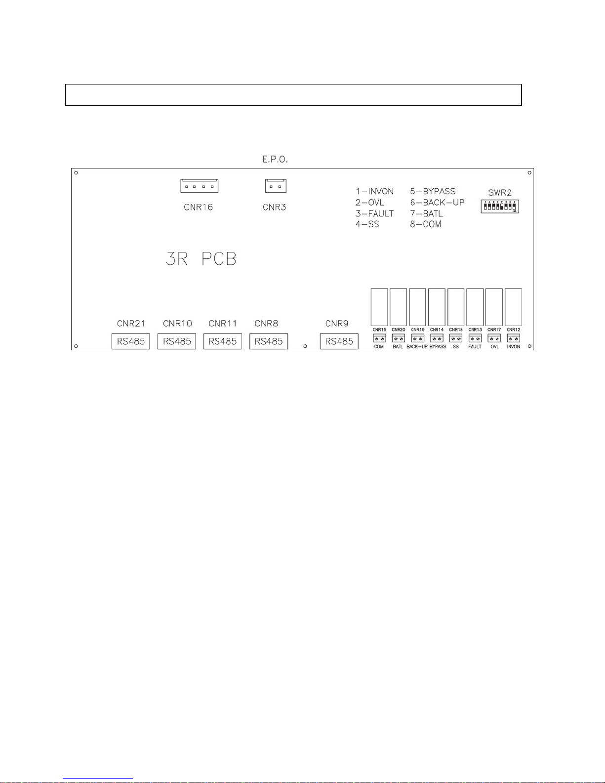
All user interfaces are connected to or from PCB 3R, see the figure below.
Figure 9.1
3R PCB Layout
9.1
Dry Contacts
Eight, normally open, dry contact terminals are provided. Maximum
16A/250VAC or 16A/30VDC.
rating is
Definitions:
•
•
INVON – Short whenever inverter is on, open when inverter is off.
to be exhausted.
• •
•
•
36
9 INTERFACE CONNECTIONS
•
OVL – Short whenever ELI is overloaded.
FAULT – Short when ELI encounters a fault condition such as high DC
shutdown, short circuit, fuse/overheat, overload shutdown, emergency stop,
inverter abnormal, and bypass on shutdown. The contact is latched until it is
manually reset (off switch) or the fault has been cleared for 30 seconds.
SS – Short when the inverter is supplying output power, open when reserve is
supplying output power (The two output will never conduct simultaneously).
BYPASS – Short when the maintenance bypass breaker is closed, open
when the breaker is opened.
BACK-UP – Short when the ELI system is in back-up mode (batteries
supplying DC Bus).
BATL – Short when low battery condition occurs and the batteries are about
M4102 Ty-Borealis 8-48KW Operators Manual v1.0 2013-08-14
Page 47
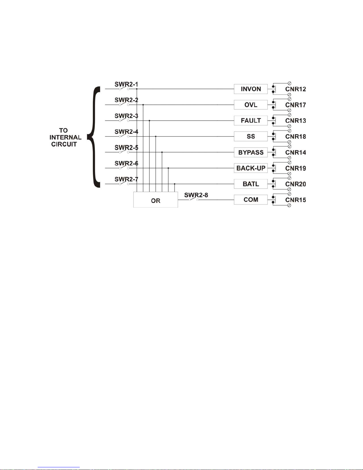
•
COM – This contact is the OR result of the signals described above. That is, if
selectable through SWR2. See the figure below.
Figure 9.2
Dry Contact Layout
9.2
Software for PC Monitoring
required to modify the signal (not included with ELI system).
9.3
Emergency Power off Connection
10mA is needed for activate the photo-coupler.
9.4
DB9 Connectors
one type of external module.
9.5
Web Monitoring Module (SNMP Module)
servers and workstations when needed.
37
any other contact closes, this contact will close too. The signal to be read is
The monitoring software allows for a server or workstation to monitor the ELI
operation. When the software is installed on a PC it can monitor 1-99 ELI’s
connected in series via a DB9 connection. The connector on the ELI side is RS-485
(for long distance transmission) therefore a RS-485 Ù RS-232 adapter (hardware) is
One pair of terminals (CNR 3) are provided to allow the user to shutdown the ELI
system in an emergency situation (e.g. fire, short circuit, etc.). A minimum of
One RS-485 and one RS-232 are provided to communicate with more
sophisticated optional communication modules. Each connector is dedicated to
Simple Network Management Protocol. The SNMP Card is an Interface to the
Ethernet network, and provides ELI information via the standard SNMP protocol.
The ELI can therefore be managed via an internet browser. This information can be
used to determine the state of the ELI and guarantee safe and orderly shutdown of
M4102 Ty-Borealis 8-48KW Operators Manual v1.0 2013-08-14
Page 48
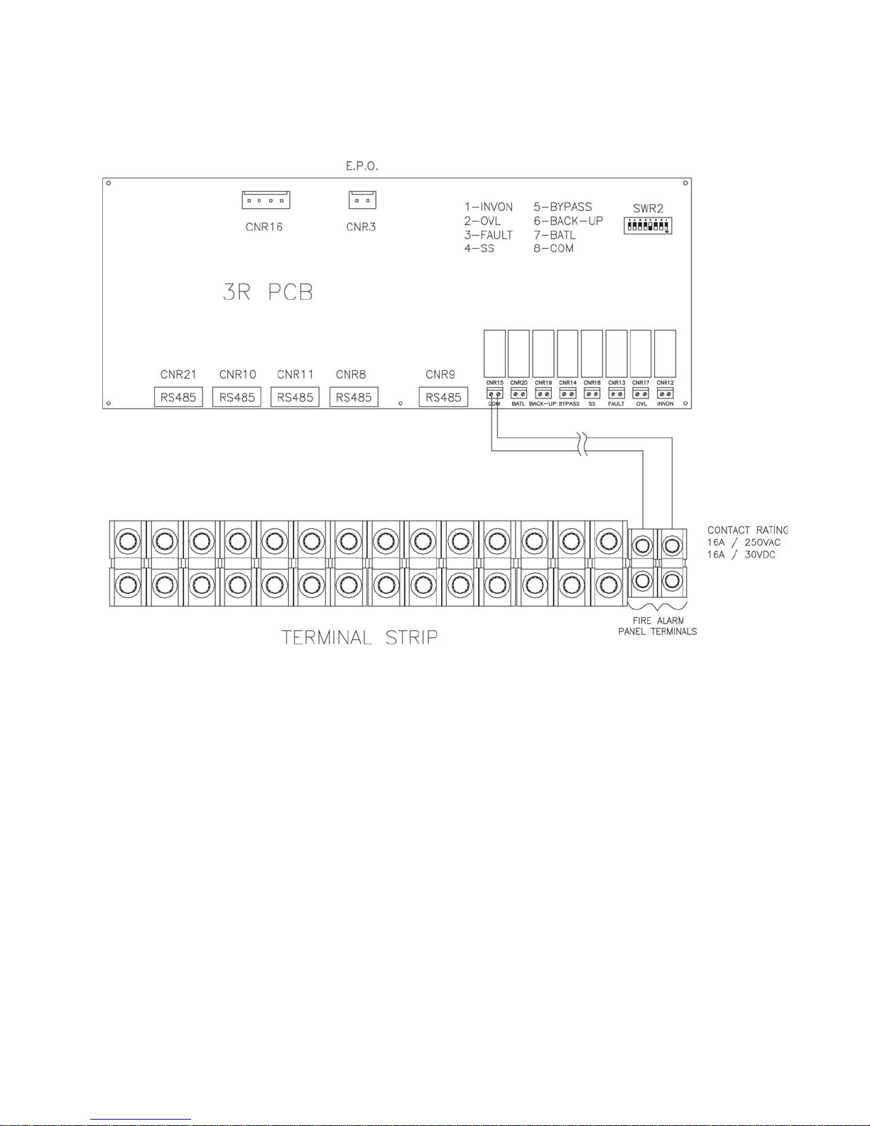
9.6
Emergency Lighting Notification
Figure 9.3
Fire Alarm Panel Terminals
* Preset at factory.
The fire alarm panel terminals fare provided to allow the fire alarm panel recognition
of the following fault conditions using normally open contacts:
1)
2)
Output overload condition
Inverter failure due to:
a.
g.
Rectifier DC output to high
Bypass activated, inverter shutdown
3)
6)
Manual bypass activation
No Output Voltage Present
38
b.
Output short circuit
c.
Inverter fuse open or over temperature condition
d.
Inverter overload condition
e.
Emergency stop activation
f.
4)
5)
Inverter output outside or parameters
Utility AC failure (on battery)
Battery low condition
M4102 Ty-Borealis 8-48KW Operators Manual v1.0 2013-08-14
Page 49

The battery cabinets have been designed with the same style and appearance as the
ELI cabinet for ease of installation and cosmetic value. Reinforcement has been added
to strengthen the cabinet for the additional weight and transportation.
Banks contain the batteries and provide the runtime for the ELI system.
The
Battery
Physicals for 3 Ø Battery Cabinet
3 Ø: Width – 1321mm, Depth – 864mm and Height – 1930mm
Figure 10.1
3 Phase Battery Cabinet Layout
39
10 Battery Backup Units (BBU)
M4102 Ty-Borealis 8-48KW Operators Manual v1.0 2013-08-14
Page 50
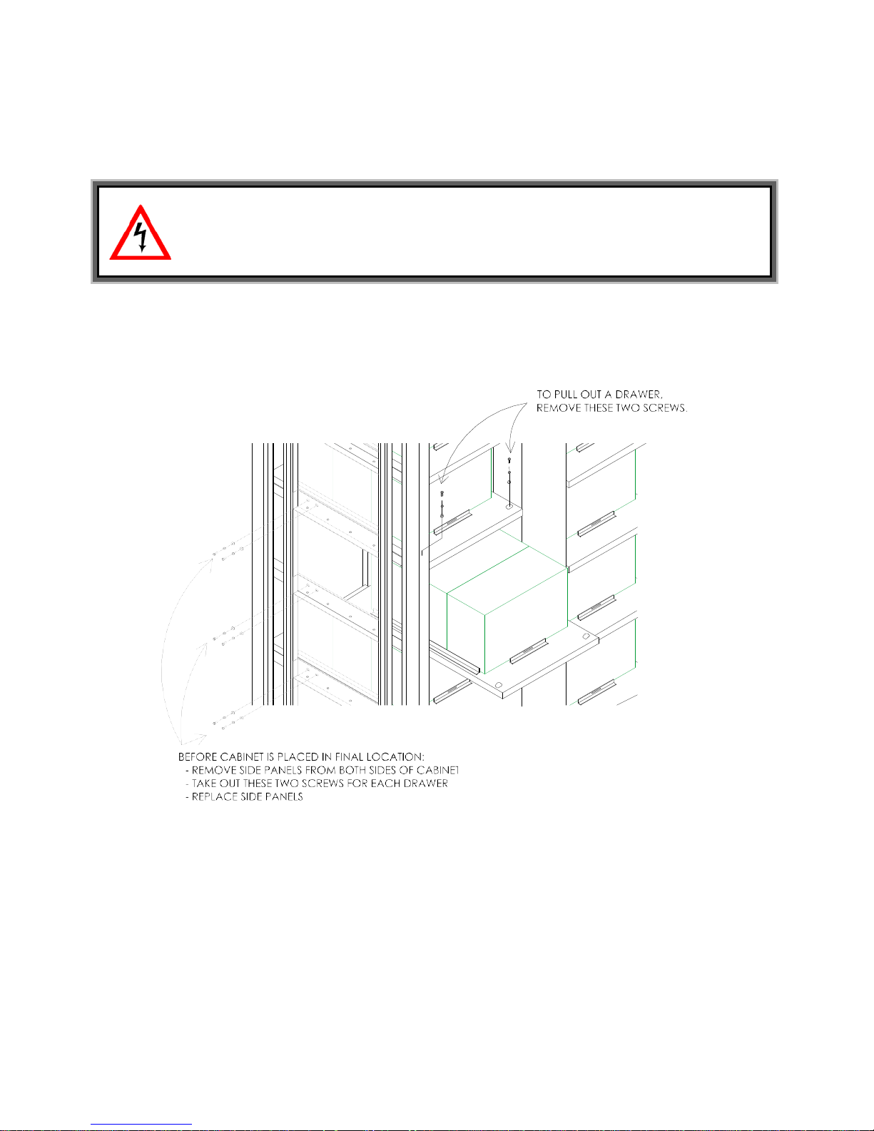
Battery cabinets feature slide-out shelves. Prior to installation of the BBU, the side panels
should have been unscrewed, allowing for ease of battery replacement.
If screws have not been properly removed prior to BBU installation, completely shut down
prior to servicing.
Figure 10.2
Slide-out BBU shelves
40
should have been removed and the screws holding the battery slide-out shelves in place
CAUTION! Only qualified service personnel should attempt battery bank
maintenance. Removal of the side access panels exposes personnel to potential
dangerous voltages and shock hazards that may cause damage, injury or death.
ELI, wait for 30 minutes until capacitors have fully discharged and disconnect ELI from BBU
M4102 Ty-Borealis 8-48KW Operators Manual v1.0 2013-08-14
Page 51

10.1
Run Time Charts
THREE PHASE 30 MINUTES BACKUP CONFIGURATIONS
THREE PHASE 60 MINUTES BACKUP CONFIGURATIONS
41
Standard Battery Systems for 60 minute runtime
Type R Battery
Maintenance-Free Sealed Lead-Acid - 10 Year Design Life Expectancy
System
Capacity Rating
WxDxH (in)
WxDxH (mm)
WxDxH (in)
WxDxH (mm)
System
Configuration
A A A A B B
Estimated
– lb/kg
Standard Battery Systems for 30 minute runtime
Type R Battery
Maintenance-Free Sealed Lead-Acid - 10 Year Design Life Expectancy
System
Capacity Rating
WxDxH (in)
WxDxH (mm)
BBU
WxDxH (in)
BBU
WxDxH (mm)
System
Configuration
A A A A A B
Estimated
– lb/kg
ELI Dimensions
ELI Dimensions
Dimensions
Dimensions
System Weight
8kW
22” x 32” x 63” 22” x 32” x 63” 22” x 32” x 63” 22” x 32” x 63” 22” x 32” x 63” 22” x 32” x 63” 22” x 32” x 63”
550 x 812 x
1,600
52” x 34” x 76”
1,315 x 850 x
1,945
12kW
550 x 812 x
1,600
52” x 34” x 76”
1,315 x 850 x
1,945
16kW
550 x 812 x
1,600
52” x 34” x 76”
1,315 x 850 x
1,945
24kW
550 x 812 x
1,600
52” x 34” x 76”
1,315 x 850 x
1,945
32kW
550 x 812 x
1,600
52” x 34” x 76”
1,315 x 850 x
1,945
40kW
550 x 812 x
1,600
2 * (52” x 34” x
76”)
2 * (1,315 x
850 x 1,945)
48kW
550 x 812 x
1,600
2 * (52” x 34” x
76”)
2 * (1,315 x
850 x 1,945)
B
2,627 / 1,194
8kW
3,113 / 1,415
12kW
3,639 / 1,654
16kW
4,352 / 1,978
24kW
5,311 / 2,414
32kW
7,713 / 3,506
40kW
8,021 / 3,646
48kW
ELI Dimensions
ELI Dimensions
22” x 32” x 63” 22” x 32” x 63” 22” x 32” x 63” 22” x 32” x 63” 22” x 32” x 63” 22” x 32” x 63” 22” x 32” x 63”
550 x 812x
1,600
550 x 812x
1,600
550 x 812x
1,600
BBU
Dimensions
BBU
Dimensions
System Weight
52” x 34” x 76”
1,315 x 850 x
1,945
3,036 / 1,380
52” x 34” x 76”
1,315 x 850 x
1,945
3,562 / 1,619
52” x 34” x 76”
1,315 x 850 x
1,945
4,066 / 1,848
52” x 34” x 76”
1,315 x 850 x
5,157 / 2,344
M4102 Ty-Borealis 8-48KW Operators Manual v1.0 2013-08-14
550 x 812x
1,600
1,945
550 x 812x
1,600
2 * (52” x 34” x
76”)
2 * (1,315 x
850 x 1,945)
7,581 / 3,446
550 x 812x
1,600
2 * (52” x 34” x
76”)
2 * (1,315 x
850 x 1,945)
9,324 / 4,238
550 x 812x
1,600
2 * (52” x 34” x
76”)
2 * (1,315 x
850 x 1,945)
B
9,632 / 4,378
Page 52

THREE PHASE 90 MINUTES BACKUP CONFIGURATIONS
*
*****
Input, output voltages are 3 phase 4 wire plus ground (wye) configuration.
Other amp ratings available. Consult factory.
42
Standard Battery Systems for 90 minute runtime
Type R
Battery
Maintenance-Free Sealed Lead-Acid - 10 Year Design Life Expectancy
System
Rating
ELI
WxDxH (in)
ELI
WxDxH (mm)
WxDxH (in)
WxDxH (mm)
Configuration
A A A B B C
Estimated
Weight – lb/kg
Capacity
Dimensions
Dimensions
BBU
Dimensions
BBU
Dimensions
System
System
**
***
****
8kW
22” x 32” x 63”
550 x 812 x
1,600
52” x 34” x 76”
1,315 x 850 x
1,930
3,485 / 1,584
12kW
22” x 32” x 63”
550 x 812 x
1,600
52” x 34” x 76”
1,315 x 850 x
1,930
4,794 / 2,179
16kW
22” x 32” x 63”
550 x 812 x
1,600
52” x 34” x 76”
1,315 x 850 x
1,930
4,871 / 2,214
24kW
22” x 32” x 63”
550 x 812 x
1,600
2 * (52” x 34”
x 76”)
2 * (1,315 x
850 x 1,930)
9,038 / 4,108
Consult factory for other voltage configurations.
Longer runtimes available. Consult factory.
Other voltage configurations available. Consult factory.
32kW
22” x 32” x 63”
550 x 812 x
1,600
2 * (52” x 34”
x 76”)
2 * (1,315 x
850x 1,930)
9,192 / 4,178
40kW
22” x 32” x 63”
550 x 812 x
1,600
3 * (52” x 34”
x 76”)
3 * (1,315 x
850 x 1,930)
13,204 / 6,002
48kW
22” x 32” x 63”
550 x 812 x
1,600
3 * (52” x 34”
x 76”)
3 * (1,315 x
850 x 1,930)
C
13,512 / 6,142
M4102 Ty-Borealis 8-48KW Operators Manual v1.0 2013-08-14
Page 53
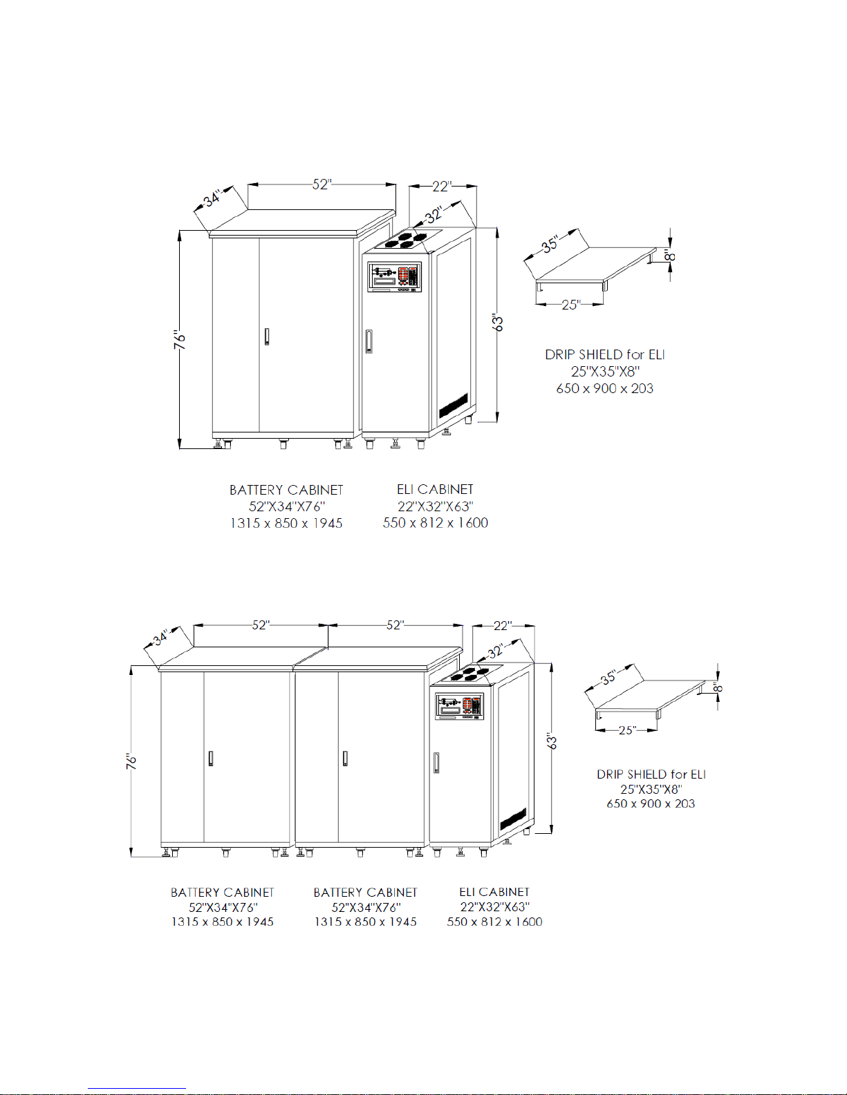
10.2
BBU Configurations
Figure 10.3
Configuration A
Figure 10.4
Configuration B
43
M4102 Ty-Borealis 8-48KW Operators Manual v1.0 2013-08-14
Page 54
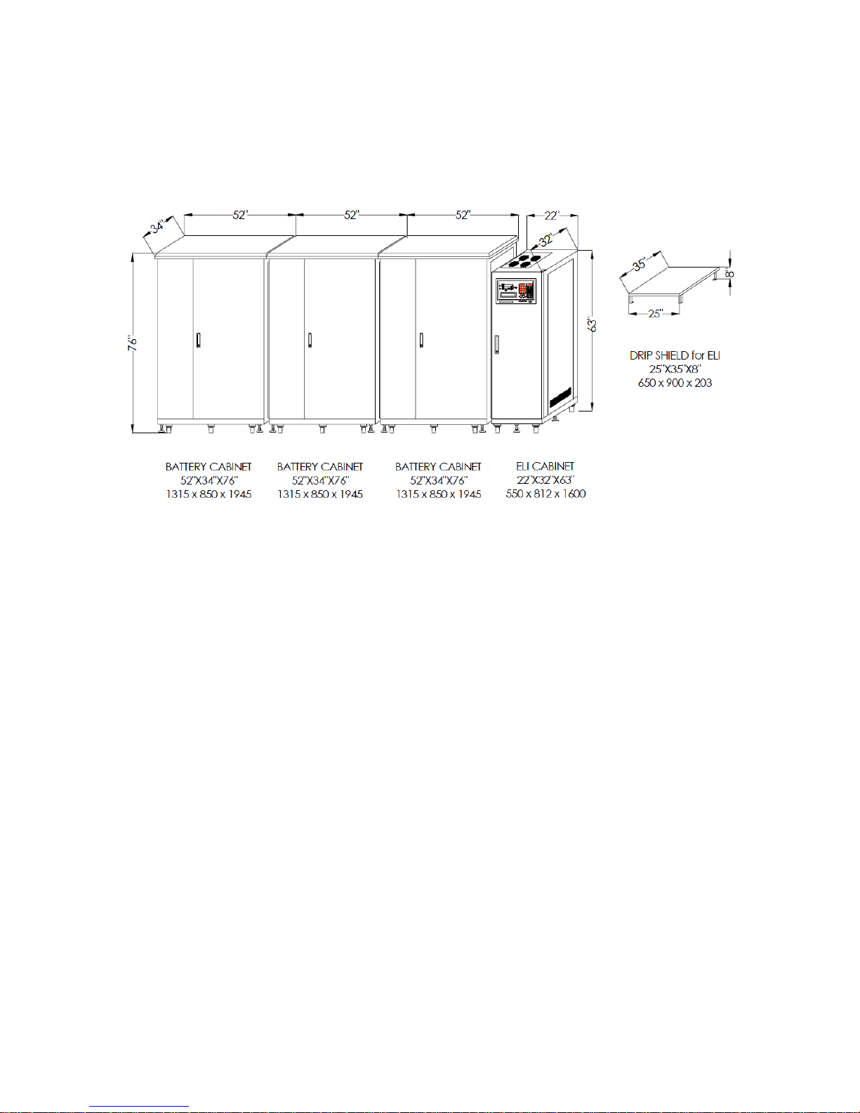
Figure 10.5
Configuration C
44
M4102 Ty-Borealis 8-48KW Operators Manual v1.0 2013-08-14
Page 55
This section provides a brief introduction to some of the options available for our ELI
system.
11.1
Emergency Stop Switch
an
d
supply at the output.
This shutdown condition is latched until a manual reset has been performed.
procedure discussed earlier to turn the system back on.
11.2
Remote Display Panel
remote monitoring of the ELI status and alarms.
11.3
12 Pulse Rectifier
the input harmonic distortion to less than 2%.
11.4
External Wrap Around Bypass
Kirk-Key interlock protection to ensure proper operation.
11.5
Normally Off Function
All Normally Off loads shall not exceed 50% of the ELI rating per phase.
45
11 Options
Warning!
Similar products from other manufacturers will not fit into our ELI systems.
The installation of any option requires professional settings and should only be
performed by the factory or factory trained representatives.
This switch is used to immediately remove power from the load in the event of
emergency condition e.g. electrical shock, burning of the load or water locate
around the ELI. When the emergency stop button is pushed, the inverter will stop
running immediately and the static switch does not activate. There will be no AC
Manual reset is performed by pressing the inverter off switch (O) and the inverter
control switch (WX) simultaneously. Once the syste m is reset follow the Start-up
The remote panel is a display module with LCD and LED’s that can monitor 1 –
99 ELI’s via a DB9 connected in series from distance < 1000m. It allows for
Located inside the ELI system cabinet. The 12-pulse rectifier is an optional
feature for 8KW to 48KW systems. The 12-pulse rectifier is designed to reduce
A separate cabinet that allows for complete removal of the ELI system from the
load, while still supplying the load with conditioned power. Systems can include
isolation transformer for different voltage configurations, distribution panels and
M4102 Ty-Borealis 8-48KW Operators Manual v1.0 2013-08-14
Page 56

8KW to 48KW ELI 3Ø Input - 3Ø Output
RECTIFIER
BATTERY
46
Normal Input
208VAC)
Maximum Input
208VAC)
12 PULSE WITH FILTER : 9%
KW Rating
8 12 16 24 32 40 48
12 Technical Specifications
Input Voltage 208V/480V/600V 3 phase 3 and 4 wire + G
Input Range 180-750V
Input Frequency 50 / 60 Hz +/- 7%
Input Power Factor < 1
Current(A) (Based
Current(A) (Based
Current THD
on
on
33
45
49
63
66
83
99
125
132
160
165
200
6 PULSE : 30% ; 12 PULSE :15%
Power Walk In (adjustable) 0% - 100% : 20 sec
Efficiency 99%
Voltage Regulation 1%
Ripple Voltage 0.5%
198
250
Battery Type Maintenance free Sealed Lead Acid
No. Of Cells 174
Voltage Range 295 – 410VDC
Maximum Charge
Current (ADC)
Battery Low
Voltage
Battery Low Stop
Voltage
Boost Charge 410VDC
Float Charge 396VDC
M4102 Ty-Borealis 8-48KW Operators Manual v1.0 2013-08-14
10
15
320VDC
295VDC
20
25
30
Page 57

INVERTER
STATIC SWITCH
47
- Mains -> Inverter
0 ms
- 100%
30 sec
- 300%
1 sec
120/208V 277/480V 347/600V 3 Phase
4 Wire + G
Output Power Factor
0.8
Voltage Regulation 100%
Unbalance Load
Frequency Lock Range
45 – 55 Hz / 55 – 65 Hz
Output Frequency (Free
Running)
Static
+/- 1%
Load step 0% - 100%
- 0%
Load step 0% - 50% 0%
100% unbalanced
load (Ph-N)
100%
Unbalance Load
KW Rating 8 12 16 24 32 40 48
DC Input Range 285 – 415VDC
Wave Form Sinusoidal
Output Voltage (Adjustable)
Crest Factor 3 : 1
+ / - 1 %
50 / 60 Hz + / - 0.1 Hz
Output
Voltage
Tolerance
+/- 3%, recovering to within +/- 1% in 1 cycle
+/- 2%, recovering to within +/- 1% in 1 cycle
+/- 2.5%
Phase Shift Under
120° + / - 0.5
THD (Linear Load) < 2 %
- <110% CONTINUOUS
- 110 – 125% 15 min
Overload
- 125 – 150% 10 min
- > 150% 60 sec
Efficiency (100% Load) 93% 93% 93% 93% 93.5% 93.5% 94%
Maximum Output Wattage (kW) 8
12
16
24
32
40
48
Voltage Range +- 20% of input voltage (Line to Neutral)
Frequency Range 45 – 55 Hz / 55 – 65 Hz
Efficiency 99.5%
Transfer
Time
- Inverter -> Mains 0 ms
Overload
Isolation With Output YES
M4102 Ty-Borealis 8-48KW Operators Manual v1.0 2013-08-14
Page 58

OVERALL CHARACTERISTICS
All specifications mentioned above are subject to change without prior notice.
48
KW Rating 8 12 16 24 32 40 48
Overall Efficiency 91% 91% 91% 91% 91.5% 92% 92%
Operating Environment:
- Temperature 0 – 40°C (32 – 104°F)
- Humidity 0% - 95% (non–condensing)
- Altitude <1500 m above sea level
Maximum Heat Dissipation(kW) 1.2 1.2 1.3 1.9 2.6 3 3.5
Weight(kg) 250 275 300 400 480 550 680
Dimension:
- HEIGHT(mm) 1600
- WIDTH(mm) 559
- DEPTH(mm) 815
- Audible Noise < 65 dBA (AT 1 m)
Standards:
- CSA Yes
- CE Yes
- EN50091-1,-2 Yes
- FCC Part 15 Class A Yes
Protections:
- Short Circuit Rectifier, Reserve, Bypass NFB
- Lightning MOV
- EMC Filter Input & Output
- Galvanic Isolation Between Input & Output
Data Display By LCD Yes
Indications & Alarms:
- LED, LCD, Buzzer Yes
Dry Contact Yes
Battery Start Yes
M4102 Ty-Borealis 8-48KW Operators Manual v1.0 2013-08-14
Page 59

Specification Table for Three Phase Inverters
250A
30.8A
49
Input // Output
208/120 // 480/277
Voltage
Combinations
480/277 // 480/277
Available 3
phase
600/347 // 480/277
AC Input
208/120V –
208/120V –
Voltage- Input
480/277V – 20A
480/277V – 30A
480/277V – 40A
480/277V –
480/277V –
600/347V – 15A
600/347V – 30A
600/347V – 30A
600/347V – 80A
600/347V – 90A
in Amperes
208/120V –
208/120V –
208/120V –
208/120V –
at 100% Load
600/347V –
11.6A
15.4A
23.1A
Model Size
Output Power
Factor
Service Amps
8kW
208/120V – 50A 208/120V – 70A 208/120V – 90A
12kW
16kW
24kW
32kW
0.8
208/120 // 208/120
480/277 // 208/120
600/347 // 208/120
208/120 // 600/347
480/277 // 600/347
600/347 // 600/347
208/120V –
125A
480/277V – 60A 480/277V – 80A
600/347V – 50A 600/347V – 60A
208/120V –
175A
40kW
225A
100A
48kW
125A
Output Voltage
and Maximum
Output Current
208/120V –
22.3A
480/277V – 9.7A
7.7A
33.4A
480/277V –
14.5A
600/347V –
44.5A
480/277V –
19.3A
600/347V –
Standard
Charger Size
(amps)
DC System
Voltage
10
10
10
M4102 Ty-Borealis 8-48KW Operators Manual v1.0 2013-08-14
66.7A
480/277V –
28.9A
600/347V –
15
348VDC nominal
88.9A
480/277V –
38.5A
600/347V –
20
208/120V –
111.1A
480/277V – 48.2A
600/347V – 38.5A 600/347V – 46.2A
25
208/120V –
133.3A
480/277V – 57.8A
30
Page 60

50
13 Contact Information
Tycor UPS Systems Inc.
Website: www.tycorups.com
Email: [email protected]
Phone: (250) 765-8448
2646 Dry Valley Rd.
Kelowna, BC, V1V 2K1
M4102 Ty-Borealis 8-48KW Operators Manual v1.0 2013-08-14
Page 61

51 52
M4102 Ty-Borealis 8-48KW Operators Manual v1.0 2013-08-14
 Loading...