

Tycon Systems ProWeatherStation TP3000WC Operation Manual

8000060 Rev 1 23-Feb-18
1
Solar Powered Wireless Wi-Fi Weather Station
TP3000WC Operation Manual
About this manual
Thank you and congratulations on selecting this professional weather station! We are sure you
will enjoy the benefits of accurate weather readings and the precise network time information
that this weather station offers. This manual will guide you step-by-step through setting up your
device. Use this manual to become familiar with your ProWeatherStation, and save it for future
reference.
Glossary of Common Terms
LCD
“LCD” is an acronym for ”Liquid Crystal Display”. This is a common type of display screen
used in televisions, computers, watches, and digital clocks.
BAROMETER & BAROMETRIC PRESSURE
A barometer is a device that measures the pressure of the air pushing on it—this
measurement is called the barometric pressure. We don’t actually feel the barometric
pressure because the air pressure is pushing equally in every direction.
RELATIVE AIR PRESSURE
Relative air pressure is the same as the barometric pressure. The calculation of relative air
pressure is a combination of the absolute air pressure and the altitude.
ABSOLUTE AIR PRESSURE
Absolute air pressure is the actual air pressure on the barometer without regard to altitude.
INCHES OF MERCURY (inHg)
Inches of Mercury is the common unit of measurement for air pressure in the United States.
HECTOPASCALS (hPa)
Hectopascals are the common units of measurement for air pressure in the International
System (SI) of measurement. The hectopascal holds the same value
Important Note:
The ProWeatherStation TP3000WC comes fully assembled for ease of use. The Outdoor
Sensor array runs mainly on solar power which charges a super capacitor located inside the
unit, but has 2 AA batteries for backup power when needed (ie; solar panel shaded or covered
with snow). The outdoor sensor array communicates with the display console over a 433Mhz
RF signal which sends the data to the display console about every 48 seconds. The display
console can be run on batteries to just display the weather readings or it can be powered using
the included 5V adapter to enable the WiFi capabilities of the display console. Once the unit is
connected to a local WiFi network the display console can upload data automatically to
Weather Underground without the need for a PC and can also be accessed from a PC running
the WeatherSmart Wifi software.
8000060 Rev 1 23-Feb-18
2
OVERVIEW
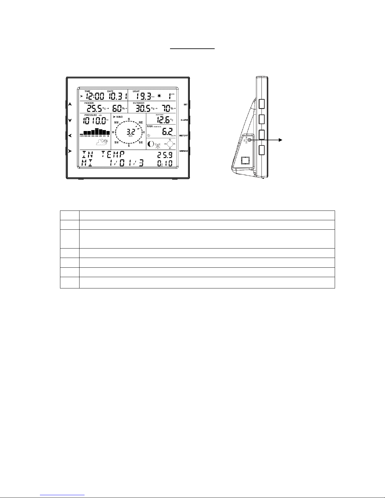
Display console
QTY
Item
1
Display Console with Wifi connectivity and Temp/Humidity/Barometric Pressure sensors.
1
Outdoor sensor (Temp/Humidity / Rain Gauge / Wind Speed Sensor/ Wind Direction/
Light-UV Sensor)
1
U-bolts (Qty 2) with mounting plate
1
120/220VAC 5V 500mA Adapter (required for WiFi communications)
1
Weathersmart WiFi PC Software on CD-Rom
1
User Manual
Features
Time and date, Moon phase.
Indoor temperature and humidity
Outdoor temperature and humidity
Wind chill, wind direction.
Rainfall. Display rain level and rainfall data in 24 hours, one week, one month, one year,
total rain and rainfall event.
Wind speed in mph, km/h, m/s, knots or Beaufort.
The direction of the wind with 360 degree range.
Wind chill, dew point and heat index temperature display.
Barometric, weather forecast.
MAX, MIN value with time stamp. High/ low alarm.
Light and UV index.
NonVolatile Memory; Saves the data when batteries are changed.
Weathersmart WiFi PC software
Upload data to Weather Underground.
5VDC connector
8000060 Rev 1 23-Feb-18
3
Proweatherstation Setup
Warning: Any metal object may attract a lightning strike, including your weather station
mounting pole. Never install the weather station during a storm.
Warning: Installing your weather station in a high location may result in injury or death.
Perform as much of the initial checkout and assembly on the ground, preferaby inside a
building or home. Only install the weather station on a clear, dry day.
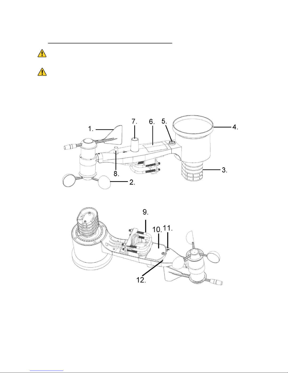
1. Sensor Array Components
1. Wind Vane
2. Wind Speed Sensor
3. Temperature and Humidity sensor
4. Rain collector
5. Bubble level
6. Solar panel for power
7.UV/Light
8. Antenna
8000060 Rev 1 23-Feb-18
4
9. U-Bolts
10. Battery compartment
11. Reset button
12. LED Indicator: light is on for 4s if the unit powers up. Then the LED will
flash once every 48 seconds (the sensor transmission update period).
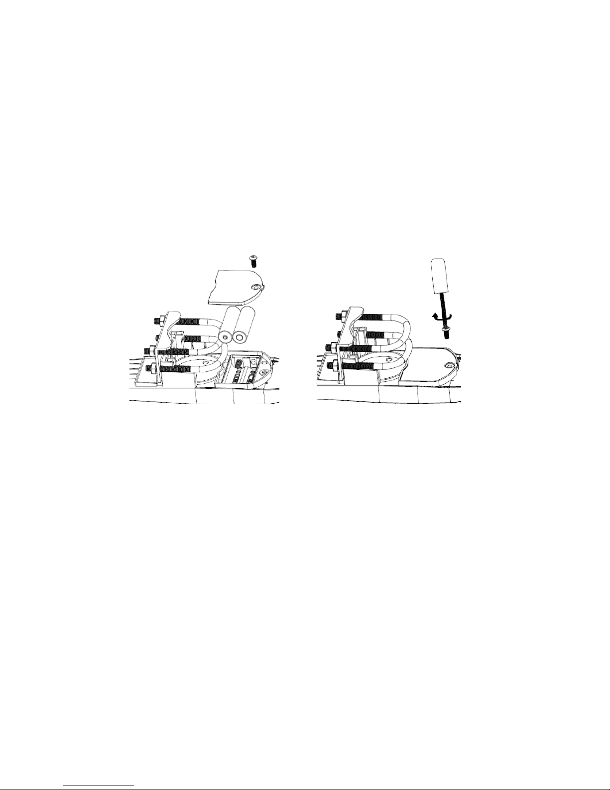
2. Install Batteries
The sensor array is powered by the solar panel which charges a super capacitor, but
batteries are required as a backup power source. Insert 2X AA batteries in the battery
compartment and tighten the screw of battery cover. The LED indicator on the back of
the transmitter will turn on for four seconds and normally flash once every 48 seconds
(the sensor transmission update period).
Figure 4
Note: If no LED light or if LED is on steady, make sure the batteries are inserted
correctly. If still an issue press the reset button momentarily. Caution ! Do not install
the batteries backwards as you can permanently damage the outdoor sensor.
Note: We recommend lithium batteries for cold weather climates, but alkaline
batteries are sufficient for most climates. We do not recommend rechargeable batteries.
They have lower voltages, do not operate well at wide temperature ranges, and do not last
as long.
3. RF (Radio Frequency) Receiving Mode
1. After power-up, the display console waits for an RF signal from the sensor array
for 144s.
2. Once synchronized, the sensor array will transmit a data update every 48 seconds.
If the display station does not receive a signal from the sensor array for eight
48s time-periods, the outdoor temperature and humidity will display “----”. The
display console will start to search for a new signal from the outdoor sensor array for 144s.
3. If the display console loses sync permanently with the outdoor sensor array, press the
8000060 Rev 1 23-Feb-18
5
reset button, located on the bottom of the outdoor sensor array, for 3 seconds. If still a
problem, remove the batteries from the outdoor sensor array, cover the solar panel, wait at
least 60 seconds and then replace the batteries.
4. Do not press any key on the display console before outdoor sensor data is received,
otherwise the outdoor sensor sync mode will be terminated. When the outdoor sensor
array transmitter has been registered, the base station will automatically switch to the
normal display mode from which all further settings can be performed by the user.
Note:
The open field distance between the display console and the outdoor sensor array can
reach up to 300 feet providing that there are no interfering obstacles such as buildings,
trees, vehicles, high voltage lines, etc. In normal use, the display console is indoors and
the sensor array is outdoors so there are walls in-between and workable distance will be
less.
Radio interference such as PC monitors, radios or TV sets can interfere with radio
communications between the sensor array and display console. Please take this into
consideration when choosing the location of the display console. If you have issues with
connecting to the outdoor sensor array, try a different location for the display console.
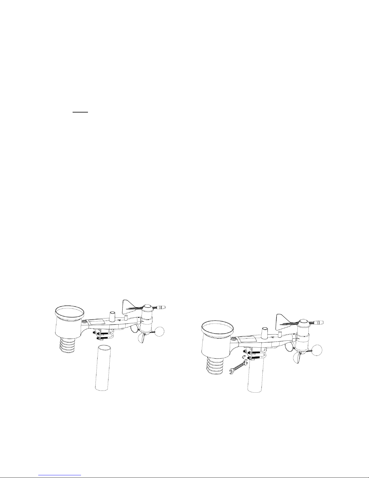
4. Mount outdoor sensor
Reference Figure 5. The mounting assembly includes two U-Bolts and a bracket that
tightens around a 1 to 2” diameter pole (not included) using the four U-Bolt nuts. There is
a bubble level built into the sensor array. Use the bubble level to mount the sensor array
as close to level as possible. It is level when the bubble is inside the red circle.
There are markings for N, S, E and W around the Wind directrion meter. Make sure when
mounting the outdoor sensor array that the “N” marking is aligned with North.
Figure 5
5. Reset Button and Transmitter LED
In the event the sensor array is not transmitting, reset the sensor array.

8000060 Rev 1 23-Feb-18
6
With an open ended paperclip, press and hold the RESET BUTTON for three seconds
to completely discharge the voltage.
If still an issue, remove the batteries from the senor array and cover the solar panel for
at least one minute.
Put batteries back in and resynchronize with display console by powering down and up
the display console with the sensor array about 3 meter away.
RESET button
LED light
Figure 6
6. Best Practices for Wireless Communication
Wireless communication is susceptible to interference, distance, walls and metal barriers.
We recommend the following best practices for trouble free wireless communication.
1. Electro-Magnetic Interference (EMI). Keep the display console several feet away
from computer monitors and TVs.
2. Radio Frequency Interference (RFI). If you have other 433 MHz devices and
communication is intermittent, try turning off these other devices for troubleshooting
purposes. You may need to relocate the transmitters or receivers to avoid intermittent
communication.
3. Line of Sight Rating. This device is rated at 300 feet line of sight (no interference,
barriers or walls) but typically you will get 100 feet maximum under most real-world
installations, which include passing through barriers or walls.
4. Metal Barriers. Radio frequency will not pass through metal barriers such as
aluminum siding. If you have metal siding, align the remote and console through a
window to get a clear line of sight.
The following is a table of reception loss vs. the transmission medium. Each “wall” or
obstruction decreases the transmission range by the factor shown below.

8000060 Rev 1 23-Feb-18
7
Medium
RF Signal Strength Reduction
Glass (untreated)
5-15%
Plastics
10-15%
Wood
10-40%
Brick
10-40%
Concrete
40-80%
Metal
90-100%
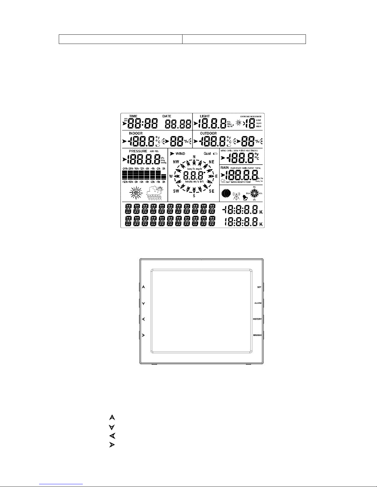
7. Display Unit Setup
1. Display Console Layout:
1.Time
2.Indoor Temperature &
3.Indoor Humidity
4.Barometric Pressure
5. Barometric Pressure graph
6.Weather icon
7. Dynamic information display area
8.RF signal
9.Memory status
10.Wind direction
11.Rain fall
12.Wind speed/Gust speed
13.wind chill/Dew point/Heat index
14.Outdoor Humidity
15.Outdoor Temperature
16.UV index
8000060 Rev 1 23-Feb-18
8
17.Light
18.Date
2. Initial Display Console Set Up
1.The unit will turn on all segments of the LCD for 3 seconds after power on. Then the
unit will start to register the outdoor sensor array which takes 3 minutes.
2. Full display
3.Key function
SET: Enter the setting mode
ALARM: Display high or low alarm function / turn on/off the alarm
HISTORY: Display history records / return to normal mode
MAX/MIN: Display the MAX, MIN value
: Move to previous information/Increase the value
: Move to next information/decrease the value
:: Move to previous segment/move to main menu during setting.
:: Move to next segment/ move to sub menu during setting.

8000060 Rev 1 23-Feb-18
9
Console Operation
Note: Many display console settings can be set in the Weathersmart WiFi PC
software. In order to do this, the software needs to be installed on a PC and the
display console needs to be connected to your WiFi network. Instructions are
located later in this user guide.
Program mode
The screen is divided into 10 segments for selection and there is a message display panel on
the bottom.
There are six program modes: normal, setting mode, history mode, alarm mode, max/min
mode and calibration mode. All the modes can be exited at any time by pressing the HISTORY
key, or waiting for a 30 second timeout to take effect.
Normally, if the segment selected has multiple parts, press SET key to choose different part.
Example: the current section is RAIN, you can press SET key to select among RAIN RATE,
RAIN EVENT, DAY, WEEK, MONTH, YEAR and TOTAL.
1. Quick Display Mode (Quick Display is located on the bottom of the screen and it scrolls
through updates every 5 Seconds. If you have selected to display “light”, the quick
display will scroll through all readings related to light)
In the normal mode press” ”or” ” key to switch among different segments. The
respective chosen segment will be marked with the arrow symbol” ”. And there will be
corresponding information display on the message board which is the lower 2 lines on the
screen.
The 11 digits on left are used to display text, the right side displays figures. The display will
automatically switch after a few seconds. Or use the “ ” or “ ” keys to manually switch the
display.
If there are alarms occurred, the alarm information will be displayed in real time as well.
 Loading...