

Page 1

8000060 Rev 3 19-Feb-19 TyconSystems.com
1
Solar Powered Wireless Wi-Fi Weather Station
TP3000WC Operation Manual
Contents
Glossary of Common Terms ...................................................................... 2
OVERVIEW ............................................................................................... 4
Display console .................................................................................. 4
Features ............................................................................................. 4
ProWeatherStation™ Setup ...................................................................... 5
1. Sensor Array Components ............................................................. 6
1.2. Install wind vane (If required) ............................................... 8
1.3. Install wind speed sensor (Anemometer) (if required) ........ 9
1.4. Install Batteries .................................................................... 9
1.5. Mount outdoor sensor ........................................................ 10
1.5 Reset Button and Transmitter LED ..................................... 10
2. Best Practices for Wireless Communication ................................ 11
3. Display Unit Set up ....................................................................... 13
3.1. Display Console Layout ..................................................... 13
3.2. Initial Display Console Set Up ........................................... 14
Console Operation ................................................................................... 16
Program mode .................................................................................. 16
1. Quick Display Mode (Update every 5 Seconds) .......................... 16
2. Setting Mode ................................................................................ 21
3. ALARM MODE ............................................................................. 24
4. Max/Min Mode .............................................................................. 26
5. History mode ................................................................................ 26
Other Console Functions ......................................................................... 27
Weather Tendency indicators ........................................................... 27
Moon Phases ................................................................................... 27
Beaufort Scales (Wind Speed) ......................................................... 28
Specification............................................................................................. 29
Page 2

8000060 Rev 3 19-Feb-19 TyconSystems.com
2
Android Software Operation .................................................................... 31
iOS Software Operation……………………...….………….……………….42
PC Software Operation ............................................................................ 57
Maintenance ............................................................................................ 64
Troubleshooting Guide ............................................................................ 65
FCC Statement ........................................................................................ 71
Warranty Information ............................................................................... 73
About this manual
Thank you for purchasing the ProWeatherStation™! This device provides
accurate weather readings and is Wi-Fi capable to stream live data from
your weather station to the internet so that users can enjoy remote
monitoring of weather conditions.
This manual will guide you step-by-step through setting up your device.
Use this manual to become familiar with your ProWeatherStation™.
Please save it for future reference.
Glossary of Common Terms
NIST
This is an internet-based time service. The display time is updated daily
to keep the time accurate on the display.
LCD
“LCD” is an acronym for” Liquid Crystal Display”. This is a common type
of display screen used in televisions, computers, watches, and digital
clocks.
BAROMETER & BAROMETRIC PRESSURE
A barometer is a device that measures the pressure of the air pushing on
it—this measurement is called the barometric pressure. We don’t feel the
Page 3

8000060 Rev 3 19-Feb-19 TyconSystems.com
3
barometric pressure because the air pressure is pushing equally in every
direction.
RELATIVE AIR PRESSURE
Relative air pressure is the same as the barometric pressure. The
calculation of relative air pressure is a combination of the absolute air
pressure and the altitude.
ABSOLUTE AIR PRESSURE
Absolute air pressure is the actual air pressure on the barometer without
regard to altitude.
INCHES OF MERCURY (inHg)
Inches of Mercury is the common unit of measurement for air pressure in
the United States.
HECTOPASCALS (hPa)
Hectopascals are the common units of measurement for air pressure in
the International System (SI) of measurement. The hectopascal holds the
same value
Important Note:
The ProWeatherStation TP3000WC comes fully assembled for ease of
use. The Outdoor Sensor array runs mainly on solar power which
charges a supercapacitor located inside the unit but has 2 AA batteries
for backup power when needed (i.e.; solar panel shaded or covered with
snow). The outdoor sensor array communicates with the display console
over a 433Mhz RF signal which sends the data to the display console
about every 16 seconds. The display console can be run on batteries to
display the weather readings or it can be powered using the included 5V
adapter to enable the Wi-Fi capabilities of the display console. When
running on batteries, you must press a key to view the display, Wi-Fi
connectivity is also disabled. Once the unit is connected to a local Wi-Fi
network the display console can upload data automatically to Weather
Underground without the need for a PC and can also be accessed from a
PC running the WeatherSmartIP software.
Page 4
8000060 Rev 3 19-Feb-19 TyconSystems.com
4
Package Contents:
Below please find the package content:
QTY
Item
1
Display Console
1
Outdoor Sensor (Temp/Humidity / Rain Gauge / Wind Speed Sensor/
Wind Direction / Light-UV Sensor)
2
U-bolt with mounting plate
1
120/220VAC 5V 500mA Adapter (Required for Wi-Fi
communications and always on display)
1
User Manual
Note:
An AC adaptor is included. Please try to place this adapter at least 0.5m
(20”) from the display console to avoid radio interference.
OVERVIEW
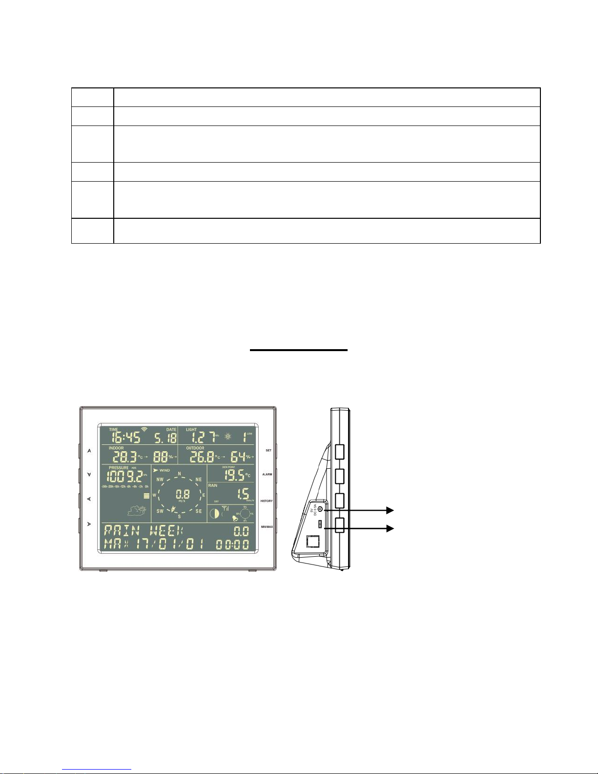
Display console
Features
⚫ Time and date, Moon phase.
⚫ Indoor temperature and humidity
⚫ Outdoor temperature and humidity
⚫ Wind chill, gust, wind direction.
⚫ Rainfall - Displays rain level and rainfall data in 24 hours, one week,
Backlight
OFF/LOW/HIGH
Adjustable
5VDC connector
Page 5
8000060 Rev 3 19-Feb-19 TyconSystems.com
5
one month, one-year, total rain and rainfall event.
⚫ Wind speed in mph, km/h, m/s, knots or Beaufort
⚫ Wind direction with 360 degrees
⚫ Wind chill, dew point, and heat index temperature display.
⚫ Barometric, weather forecast.
⚫ MAX, MIN value with time stamp. High/ low alarm.
⚫ Light and UV index
⚫ Non-Volatile Memory: Saves the data when batteries are changed
⚫ WeatherSmart Wi-Fi PC software
⚫ Uploads the data to 3 weather servers: wunderground.com,
Weathercloud, and WeatherObservationsWebsite (WOW)
ProWeatherStation™ Setup
Warning: Any metal object may attract a lightning strike,
including your weather station mounting pole. Never install the
weather station during a storm.
Warning: Installing your weather station in a high location may
result in injury or death. Perform as much of the initial checkout and
assembly on the ground, preferably inside a building or home. Only
install the weather station on a clear, dry day.
Note:
Before placing and installing all components of the weather station at
their destination, please set up the display console(receiver) and outdoor
sensor(transmitter) in a room and get familiar with the functions.
Power up sequence must be performed in the following order: Insert
batteries in the Outdoor Sensor Array first; Display Console second).
Attention:
⚫ Do not mix old and new batteries
⚫ Do not use Rechargeable batteries.
⚫ Use Lithium batteries for sensor array when the outdoor temperature
is lower than 0 degrees Celsius
Page 6
8000060 Rev 3 19-Feb-19 TyconSystems.com
6
⚫ Ensure batteries are installed with correct polarity (+/-)
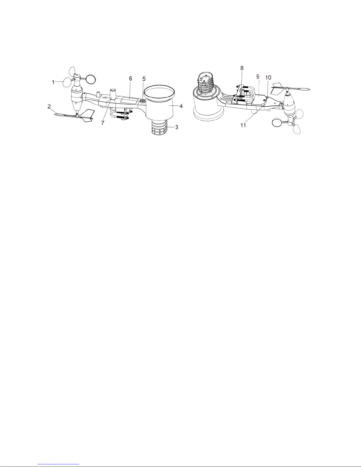
1. Sensor Array Components
Figure 1
1. Wind Speed Sensor
2. Wind Vane
3. Temp/Humidity sensor
4. Rain collector
5. Bubble level
6. Solar panel
7. Light sensor and UV sensor
8. U-Bolt
9. Battery compartment
10.Reset button
11.LED Indicator: light on for 4s if the unit powers up. Then the LED will
flash once every 16 seconds (the sensor transmission update period).
1.1 Install U-bolts and metal plate
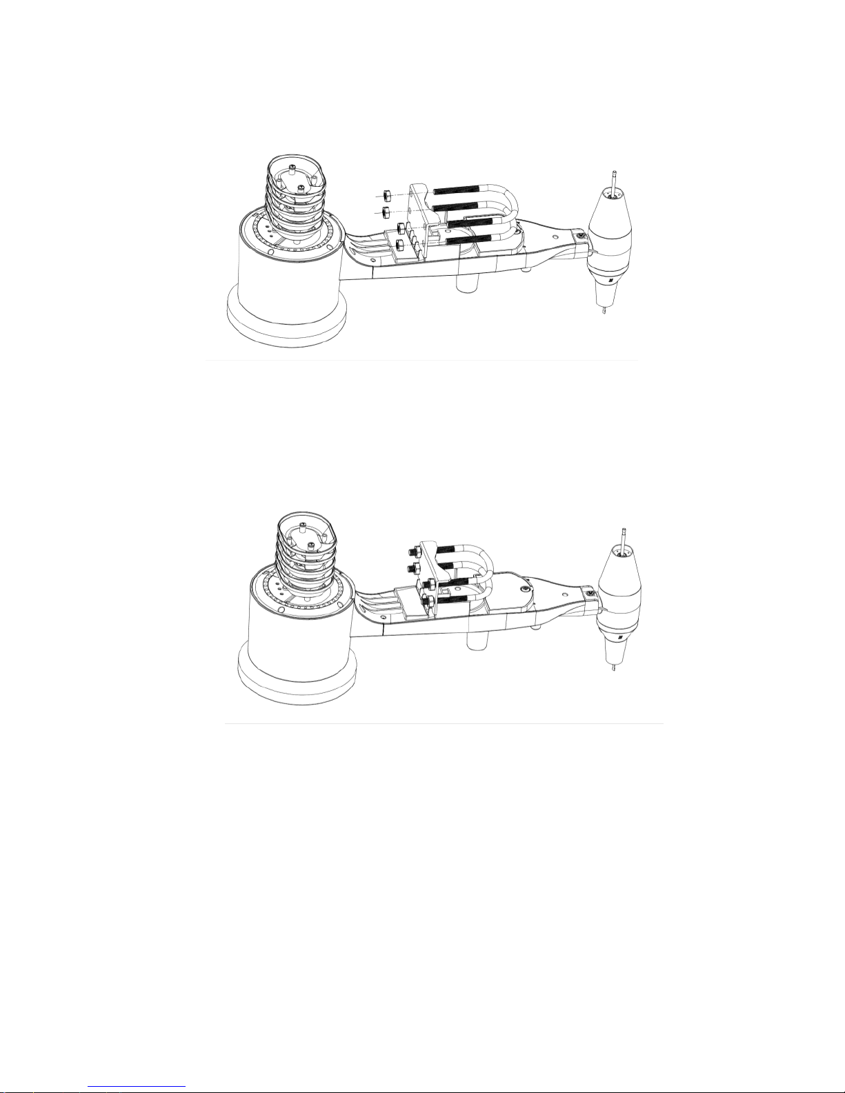
Installation of the U-bolts, which are in turn used to mount the sensor
package on a pole (pole not included), requires the installation of an
included metal plate to receive the U-bolt ends. The metal plate, visible in
Figure 3 has four holes through which the ends of the two U-Bolts will fit.
The plate itself is inserted in a groove on the bottom of the unit (opposite
side of solar panel). Note that one side of the plate has a straight edge
(which goes into the groove), the other side is bent at a 90-degree angle
and has a curved profile (which will end up “hugging” the mounting pole).
Page 7
8000060 Rev 3 19-Feb-19 TyconSystems.com
7
Once the metal plate is inserted, insert both U-bolts through the
respective holes of the metal plate as shown in Figure 3.
Figure 3 U-Bolt installation
Loosely screw on the nuts on the ends of the U-bolts. You will tighten
these later during final mounting. Final assembly is shown in Figure 4.
Figure 4 U-Bolts and nuts installed
The plate and U-Bolts are not yet needed at this stage but doing this now
may help avoid damaging wind vane and wind speed cups later.
Handling of the sensor package with wind vane and speed cups installed
is more difficult and more likely to lead to damage.
Page 8
8000060 Rev 3 19-Feb-19 TyconSystems.com
8
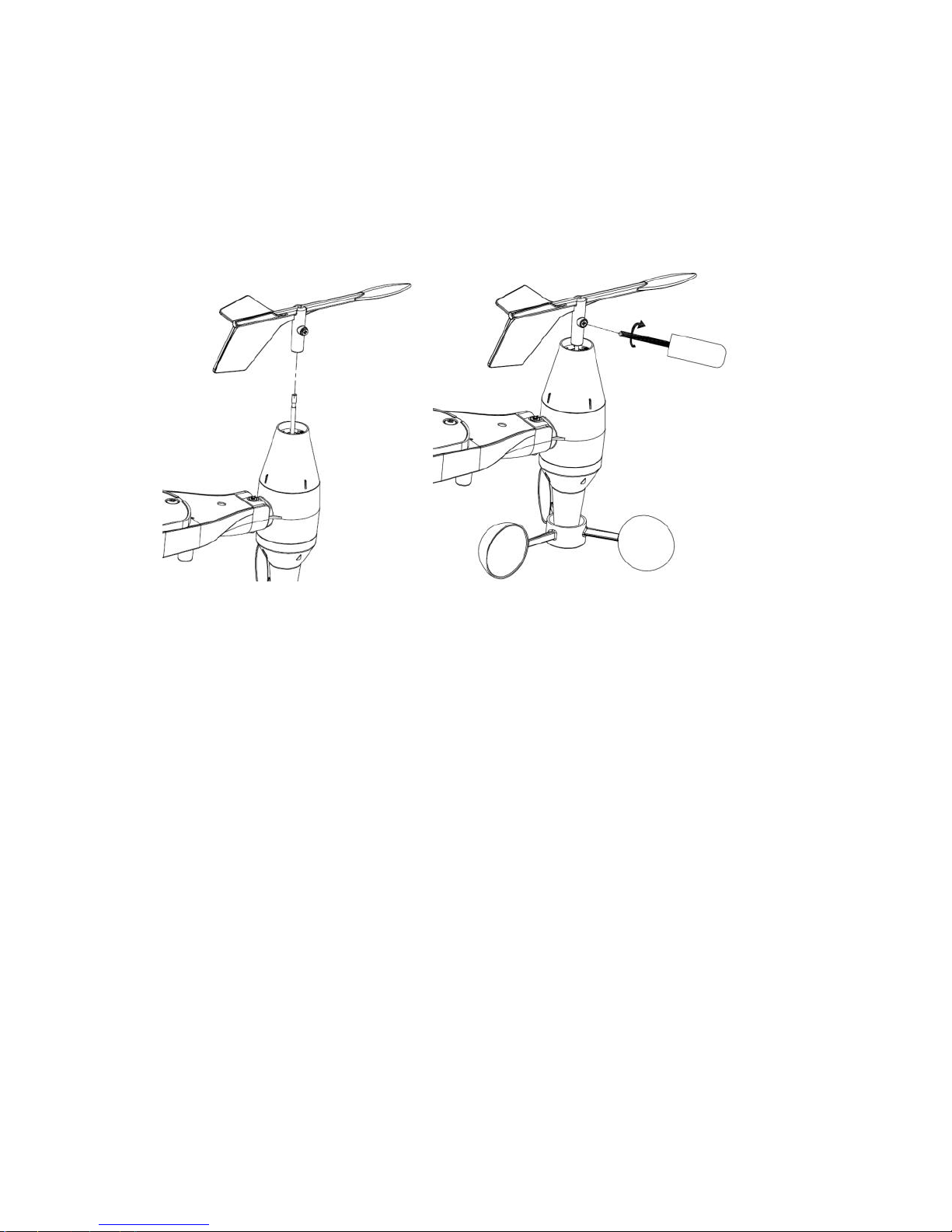
1.2. Install wind vane (If required)
Push the wind vane into the shaft. as shown in figure 5.
Tighten the set screw with as shown in figure 6. Wind vane doesn’t
move as freely as the wind speed sensor. This damping effect is
helpful in keeping wind direction measurement steady.
Figure 5 Figure 6
There are four letters: "N", "E", "S" and "W" around the wind direction
sensor, representing direction North, East, South and West. The Wind
direction sensor must be adjusted so that the directions on the sensor
are matching the real location. A wind direction error will be introduced
if the wind direction sensor is not positioned correctly during
installation.
Page 9
8000060 Rev 3 19-Feb-19 TyconSystems.com
9
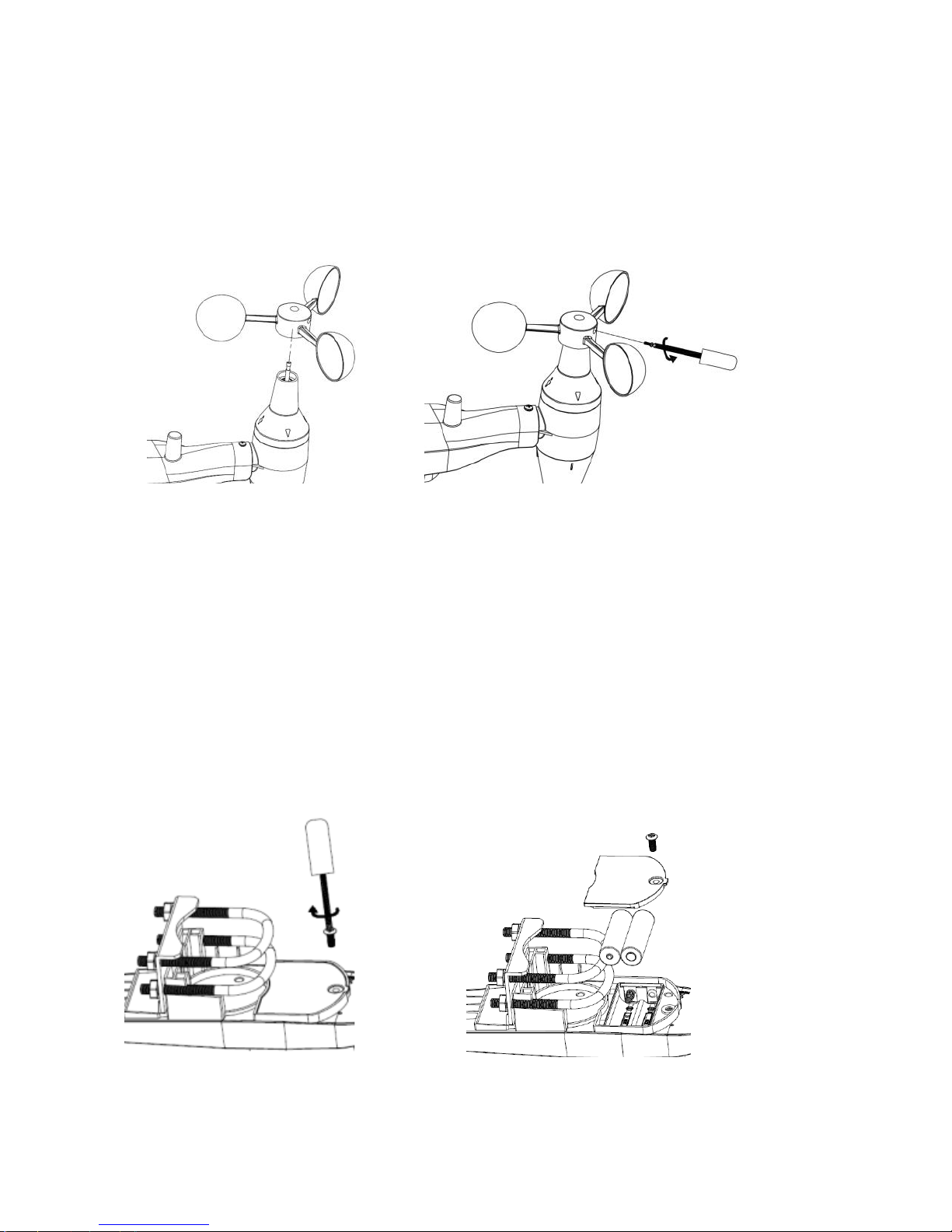
1.3. Install wind speed sensor (Anemometer) (if required)
Push the wind cup into the shaft. as shown in figure 7.
Tighten the set screw with as shown in figure 8. Make sure the wind
speed cups spin freely.
Figure 7 Figure 8
1.4. Install Batteries
Make sure the solar panel is covered, then insert 2XAA batteries in
the battery compartment. The LED indicator on the back of the
transmitter will turn on for four seconds and normally flash once every
16 seconds (the sensor transmission update period).
Figure 9 Figure 10
Page 10
8000060 Rev 3 19-Feb-19 TyconSystems.com
10
Note: If no LED lights up or is lit full time, make sure the battery is
inserted with correct polarity. Caution! Do not install the batteries
backwards as you can permanently damage the outdoor sensor.
If the LED function is not as expected, remove the batteries, wait 30
seconds and then re-install.
Note: We recommend lithium batteries for cold weather climates, but
alkaline batteries are enough for moderate climates. Rechargeable
batteries should never be used because they have lower voltages.
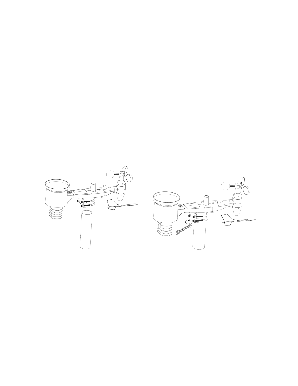
1.5. Mount outdoor sensor
Reference Figure 11 & 12. The mounting assembly includes two U-Bolts
and a bracket that tightens around a 1 to 2” diameter pole (pole not
included) using the four U-Bolt nuts.
Note: Use the bubble level beside the rain sensor as a guide to verify
that sensors are level.
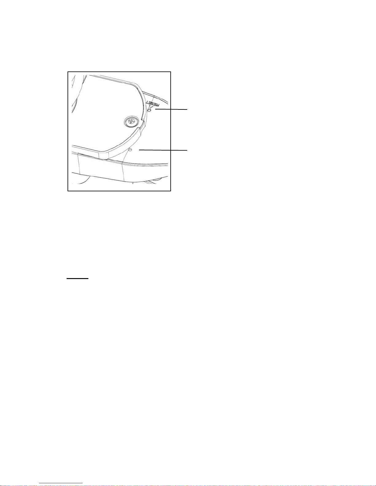
1.5 Reset Button and Transmitter LED
In the event the sensor array is not transmitting, reset the sensor
array:
With an open-ended paperclip, press and hold the RESET BUTTON
for 3 seconds to initiate a reset: LED turns on while RESET button is
Figure 11
Figure 12
Page 11
8000060 Rev 3 19-Feb-19 TyconSystems.com
11
pressed, and resumes normal operation after the Reset button is
released: LED will flash every 16s during normal operation.
Figure 13
2. Best Practices for Wireless Communication
Note:
The open field distance between the display console and the outdoor
sensor array can reach up to 300 feet providing that there are no
interfering obstacles such as buildings, trees, vehicles, high voltage
lines, etc. In normal use, the display console is indoors, and the
sensor array is outdoors so there are walls in-between and workable
distance will be less.
Radio interference such as PC monitors, radios or TV sets can
interfere with radio communications between the sensor array and
display console. Please take this into consideration when choosing
the location of the display console. If you have issues with
connecting to the outdoor sensor array, try a different location for the
display console.
RESET button
LED light
Page 12
8000060 Rev 3 19-Feb-19 TyconSystems.com
12
Wireless communication is susceptible to interference, distance, walls,
and metal barriers. We recommend the following best practices for
trouble-free wireless communications.
1. Electro-Magnetic Interference (EMI). Keep the console several
feet away from computer monitors and TVs.
2. Radio Frequency Interference (RFI). If you have other 433 MHz
devices and communication is intermittent, try turning off these
other devices for troubleshooting purposes. You may need to
relocate the transmitters or receivers to avoid intermittent
communication.
3. Line of Sight Rating. This device is rated at 300 feet line of sight
(no interference, barriers or walls) but typically you will get 100
feet maximum under most real-world installations, which include
passing through barriers or walls.
4. Metal Barriers. Radio frequency will not pass through metal
barriers such as aluminum siding or tinted windows. If you have
metal siding, align the remote and console through a window to
get a clear line of sight.
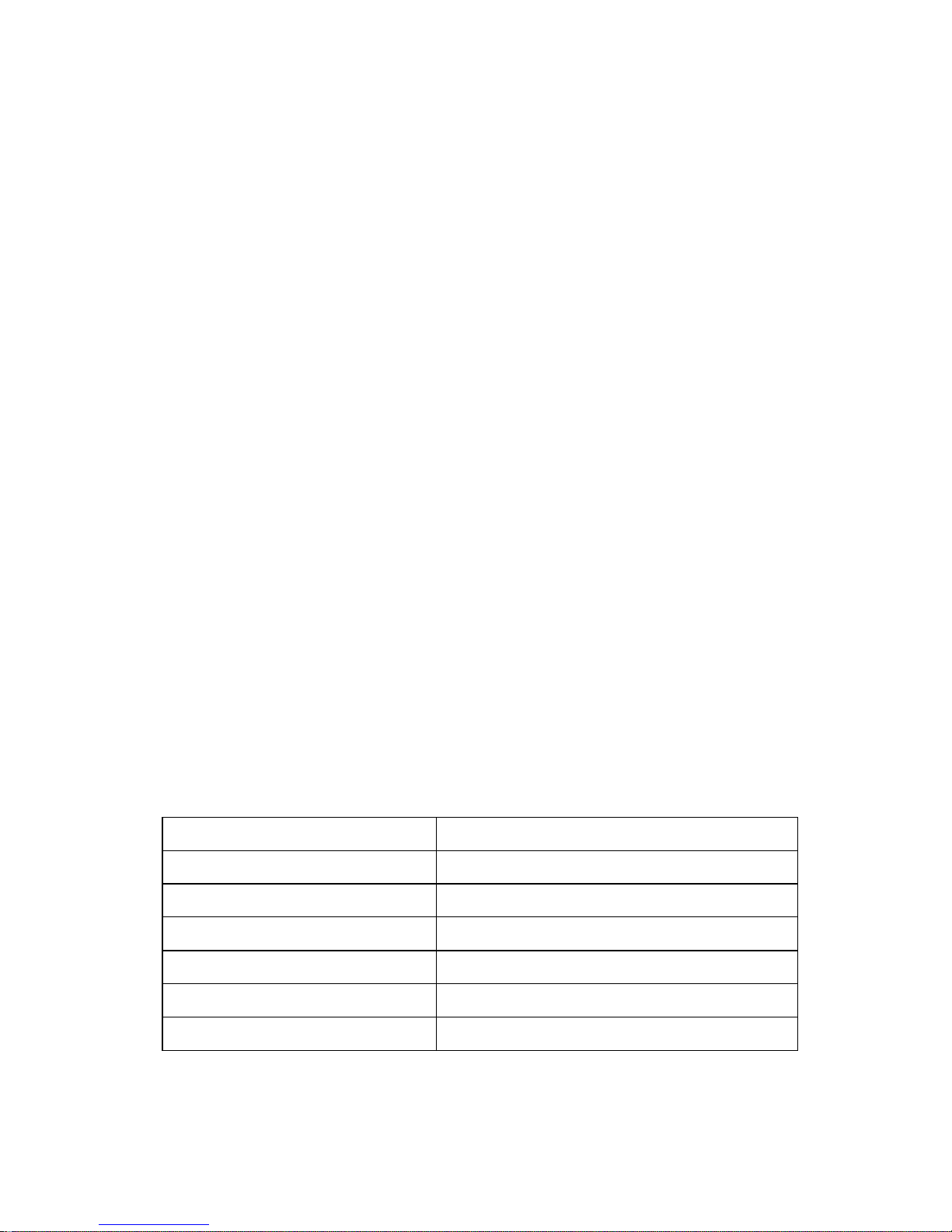
The following is a table of reception loss vs. the transmission medium.
Each “wall” or obstruction decreases the transmission range by the
factor shown below.
Medium
RF Signal Strength Reduction
Glass (untreated)
5-15%
Plastics
10-15%
Wood
10-40%
Brick
10-40%
Concrete
40-80%
Metal or Tinted Glass
90-100%
Page 13
8000060 Rev 3 19-Feb-19 TyconSystems.com
13
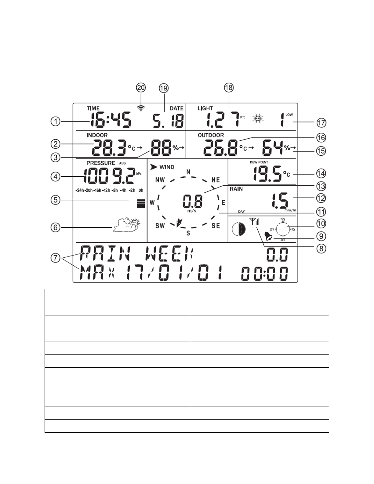
3. Display Unit Set up
3.1. Display Console Layout
1.Time
2.Indoor Temperature
3.Indoor Humidity
4.Barometric Pressure
5. Barometric Pressure graph
6.Weather Forecast icon
7. Dynamic information display area
8.RF signal
9. Alarm icon
10. Memory status
11.Wind direction
12.Rainfall
13.Wind speed/Gust speed
14. Wind chill/Dew point/Heat
index
15.Outdoor Humidity
16.Outdoor Temperature
17.UV index
18.Light
19.Date
20.Wi-Fi Signal icon
Page 14
8000060 Rev 3 19-Feb-19 TyconSystems.com
14
3.2. Initial Display Console Set Up
3.2.1 The unit will turn on all segments of the LCD for 3 seconds after
power. Then the unit will start to register the outdoor sensor array
which takes ~3 minutes.
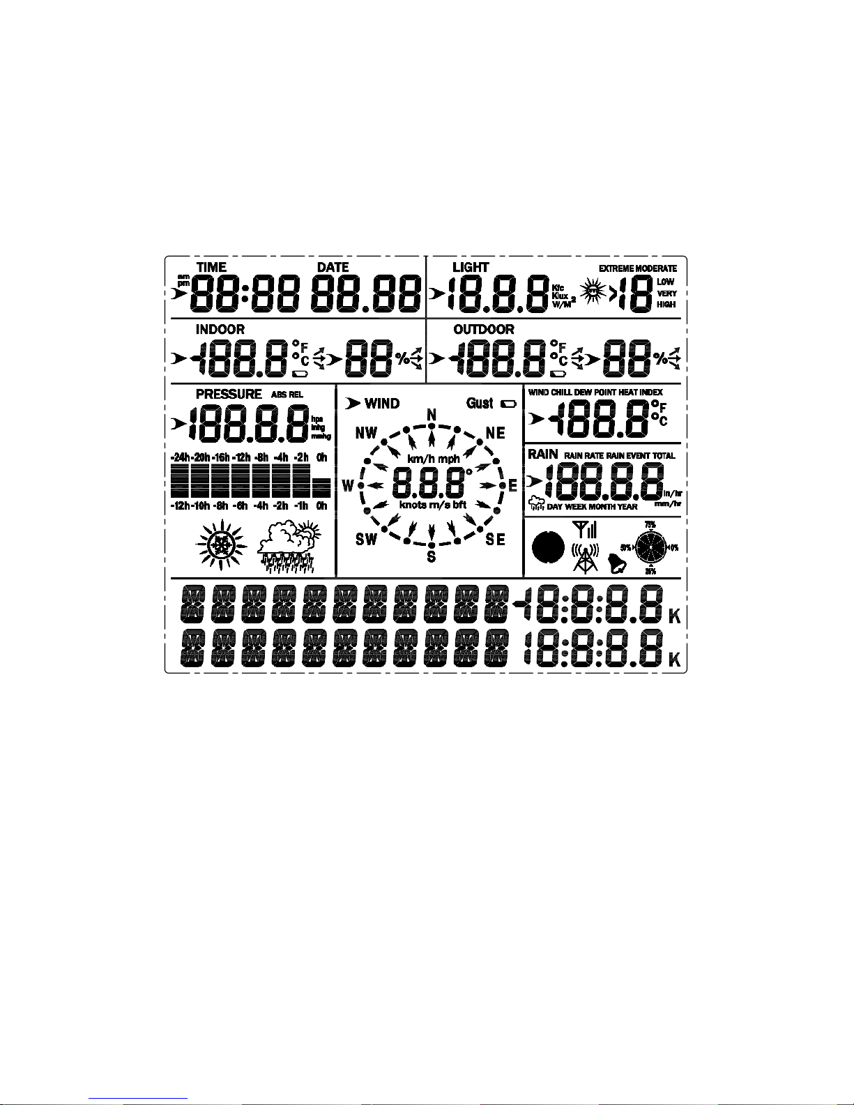
3.2.2 Full display
Page 15
8000060 Rev 3 19-Feb-19 TyconSystems.com
15
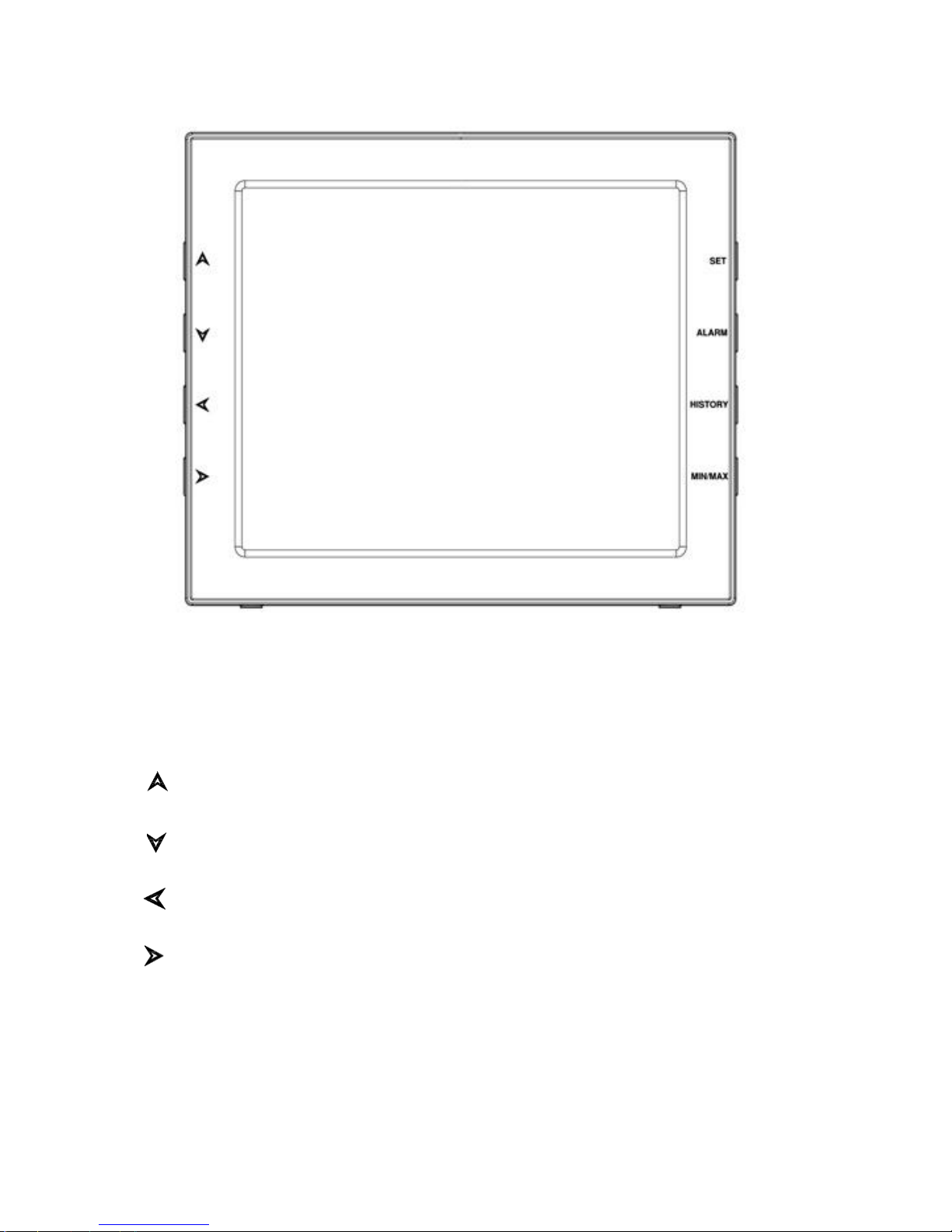
3.2.3 Key function
SET: Enter the setting mode
ALARM: Display high or low alarm function / turn on/off the alarm
HISTORY: Display history records / return to normal mode
MAX/MIN: Display the MAX, MIN value
: Move to the previous information (normal mode) or +
(programming mode)
: Move to next information (normal mode) or– (programming
mode)
: Move to previous segment/move to the main menu during
setting.
: Move to next segment/ move to submenu during setting.
Page 16
8000060 Rev 3 19-Feb-19 TyconSystems.com
16
Console Operation
Note: Multiple display console settings can be easily set up
using the WeatherSmartIP PC software. To do this, the software
needs to be installed on a PC and the display console needs to
be connected to your Wi-Fi network. Instructions on connecting
your display console are located later in this user guide (Page 31
for Android, 42 for iOS).
Program mode
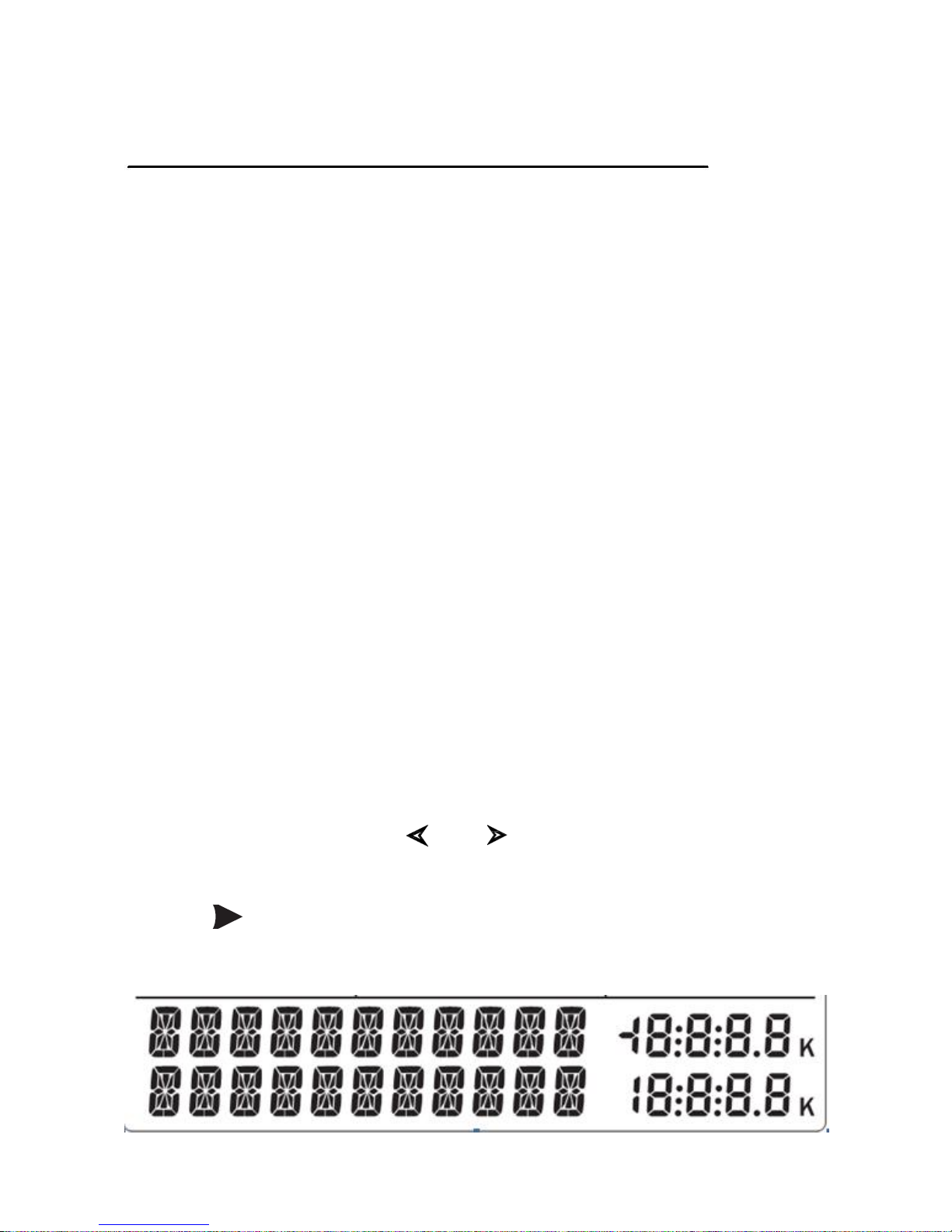
The screen is divided into 10 segments for selection and there is a
message display panel on the bottom segment.
There are six program modes: normal, setting mode, history mode, alarm
mode, max/min mode and calibration mode.
All the modes can be exited at any time by pressing the HISTORY key or
waiting for a 30-second timeout to take effect.
Normally, if the segment selected has multi parts, press the SET key to
choose different part. Example: the current section is RAIN, you can
press the SET key to alternate the display of RAIN RATE, RAIN EVENT,
DAY, WEEK, MONTH, YEAR and TOTAL.
1. Quick Display Mode (Update every 5 Seconds)
In the normal mode press” ”or” ” key to switch among different
segments. The respective chosen segment will be marked with the arrow
symbol” ”. And there will be corresponding information display on the
message board which is the lower 2 lines on the screen.
Page 17
8000060 Rev 3 19-Feb-19 TyconSystems.com
17
The 11 digits on left are used to display text, the right side displays figures.
The display will automatically switch after a few seconds. Or use the “ ”
or “ ” keys to manually switch the display.
If there are alarms triggered, the alarm information will be displayed in
real time as well.
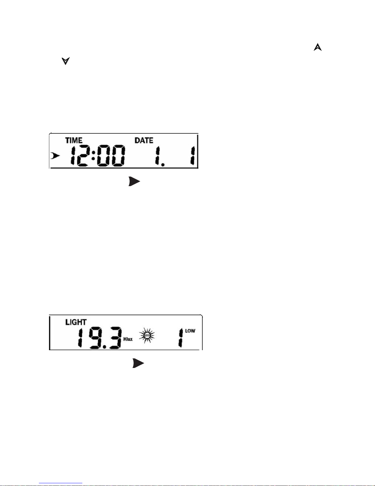
⚫ Time and date
If the arrow symbol “ ” is in this segment, the following information will
appear on the message board:
a) Year, Weekday
b) Alarm time and status of the alarm(on/off)
c) Moon phase. (Reference Section Other Console Functions/Moon
phase for detail)
d) If connected with Wi-Fi, the device time will synchronize with the
internet time (UTC Time, you need to set the time zone for local
time).
⚫ Light and UV
If the arrow symbol “ ” is in this segment, following information with
time stamp will appear on the message board:
a) The max light strength value of the day.
b) The max light strength value since the last reset
c) The max UV index value of the day.
d) The max UV index value since the last reset.
Page 18
8000060 Rev 3 19-Feb-19 TyconSystems.com
18
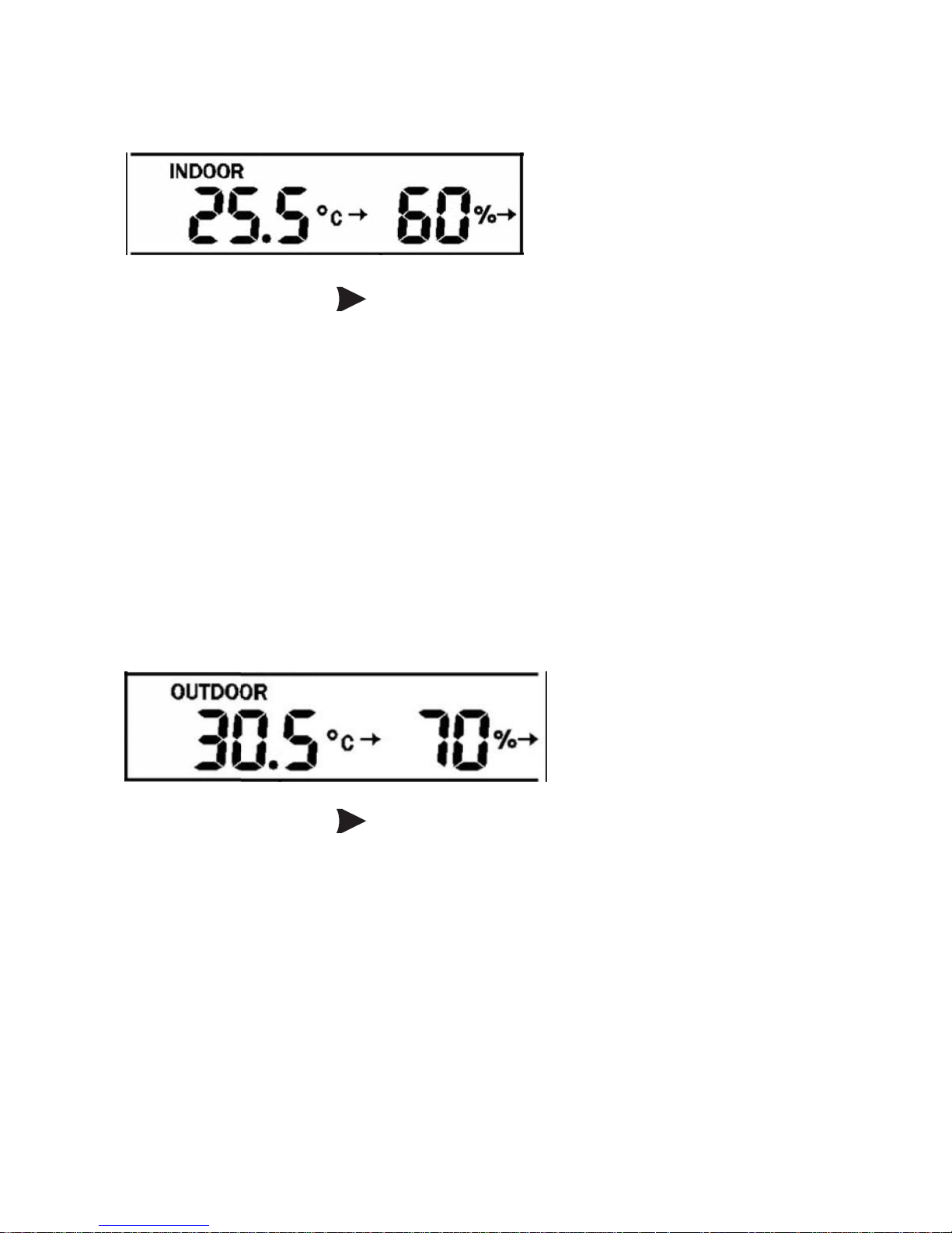
⚫ Indoor temperature
If the arrow symbol “ ” is in this segment, following information with
time stamp will appear on the message board:
a) Max indoor temperature value of the current day.
b) Min indoor temperature value of the current day.
c) Max indoor temperature value since the last reset
d) Min indoor temperature value since the last reset
e) Max indoor humidity value of the current day.
f) Min indoor humidity value of the current day.
g) Max indoor humidity value since the last reset
h) Min indoor humidity value since the last reset
⚫ Outdoor temperature/ humidity
If the arrow symbol “ ” is in this segment, following information with
time stamp will appear on the message board:
a) Max outdoor temperature value of the current day.
b) Min outdoor temperature value of the current day.
c) Max outdoor temperature value since the last reset
d) Min outdoor temperature value since the last reset
e) Max outdoor humidity value of the current day.
f) Min outdoor humidity value of the current day.
g) Max outdoor humidity value since the last reset
h) Min outdoor humidity value since the last reset
Page 19
8000060 Rev 3 19-Feb-19 TyconSystems.com
19
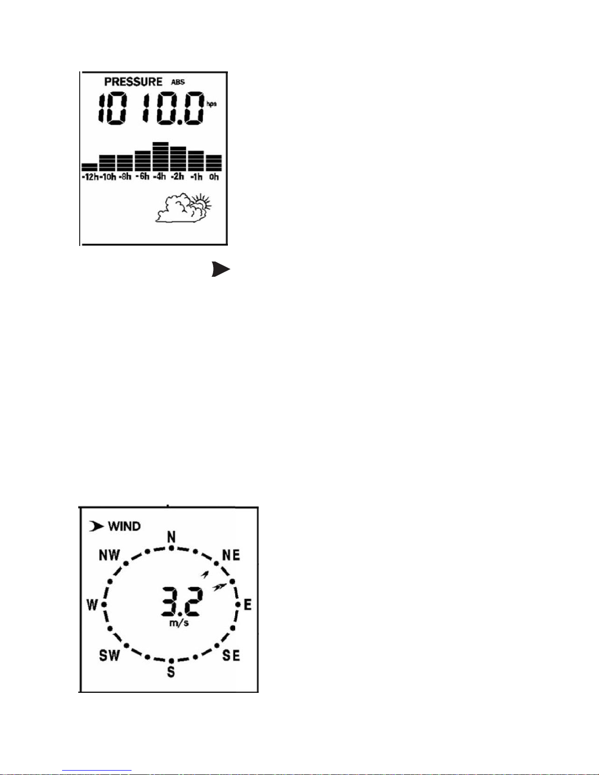
⚫ Barometric
If the arrow symbol “ ” is in this segment, following information with
time stamp will appear on the message board:
a) Max relatively barometric pressure of the current day
b) Min relatively barometric pressure of the current day
c) Max relatively barometric pressure since the last reset
d) Min relatively barometric pressure since the last reset
e) Max absolute barometric pressure of the current day
f) Min absolute barometric pressure of the current day
g) Max absolute barometric pressure since the last reset
h) Min absolute barometric pressure since the last reset
⚫ Wind and gust speed
Page 20
8000060 Rev 3 19-Feb-19 TyconSystems.com
20
If the arrow symbol “ ” is in this segment, following information with
time stamp will appear on the message board:
a) The max wind speed of the current day
b) The max wind speed since the last reset.
c) The max wind gust speed of the current day
d) The max wind gust speed since the last reset.
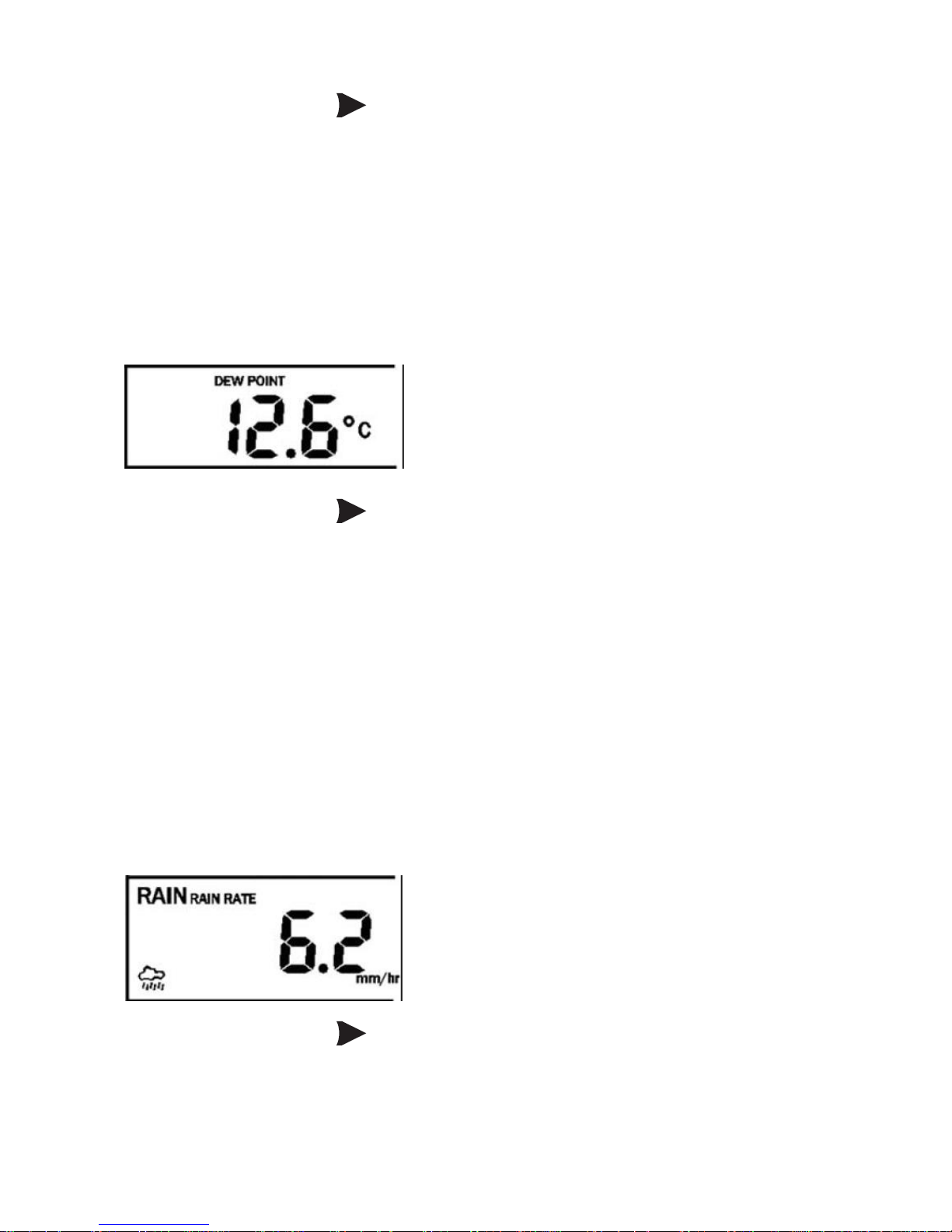
⚫ Wind chill, dew point, heat index
If the arrow symbol “ ” is in this segment, following information with
time stamp will appear on the message board:
a) Min wind chill temperature of the current day
b) Min wind chill temperature since the last reset
c) Max dew point temperature of the current day
d) Min dew point temperature of the current day
e) Max dew point temperature since the last reset
f) Min dew point temperature since the last reset
g) Max heat index of the day of the current day.
h) Max heat index of the day since the last reset
⚫ Rainfall
If the arrow symbol “ ” is in this segment, following information with
time stamp will appear on the message board:
a) Max rain rate of the current day
Page 21
8000060 Rev 3 19-Feb-19 TyconSystems.com
21
b) Max rain rate since the last reset
c) Max Rainfall data of current day
d) Max Rainfall data of last week
e) Max Rainfall data of last month
f) Max Rainfall data of last year
2. Setting Mode
2.1 In normal mode, press SET key for 2 seconds to enter the setting
mode.
Then press” ”button to transfer among different setting function:
TIME SETTING
UNIT SETTING
RECORD SAVE INTERVAL
RAIN SEASON SETTING
BAROMETRIC SETTING
KEY BEEP SETTING
CALIBRATION SETTING
TRANSMITTER ID
When the desired setting function is displayed, press the” ” key to start
the associated setting menu. Change a setting with the key /
.Hold the / key for 2 seconds will increase/decrease digits in
great steps. Press HISTORY key or wait for 30 seconds at any time, the
device will return to normal mode.
⚫ TIME SETTING
After entering setting mode, the first setting function “TIME
SETTING” will appear on the message board. Use the” ” key to
select the desired sub-functions:
a) TIME FORMAT:12H/24H
b) DATE FORMAT:MM-DD-YYYY / DD-MM-YYYY / YYYY-MM-DD
select
Page 22
8000060 Rev 3 19-Feb-19 TyconSystems.com
22
c) TIME: Manual setting of time and date
d) TIME ZONE
e) DAYLIGHT SAVING TIME: switch on/off the reception of DST.
f) NORTH/SOUTH: Set northern/southern hemisphere for moon
phase
⚫ UNIT SETTING
After entering setting mode, the first setting function” TIME
SETTING” will appear on the message board. Press” ”key to
switch to “UNIT SETTING” display.
Then use the” ” key to select the desired sub-functions:
a) Light unit select (lux, fc, w/m2)
b) Temperature unit select (C, F)
c) Pressure unit select (hpa, inhg, mmhg)
d) Wind speed unit select (km/h, mph, knots, m/s, bft)
e) Rainfall unit select (mm, inch)
⚫ RECORD SAVE INTERVAL: to set the interval of data recording.
Under setting mode, the first setting function appearing on the
message board is” TIME SETTING”, Press” ”key repeatedly to
switch to “RECORD SAVE INTERVAL” display.
Use the” ” key to start setting of recording interval.
Use the / keys to select the desired recording interval for
measured values.
⚫ RAIN SEASON SETTING
Under setting mode, the first setting function appearing on the
message board is” TIME SETTING”. Press” ”button repeatedly to
switch to “RAIN SEASON SETTING” display.
Press the” ” button to start setting of the month of rain season.
Press the / buttons to select the month from January to
December.
Rain season is the time of year when most of a region’s average
Page 23
8000060 Rev 3 19-Feb-19 TyconSystems.com
23
annual rainfall occurs. Rain season influences the annual rainfall
maximum, minimum and total value. The annual rainfall and annual
max/min rainfall resets at 12:00 AM of the first day of the selected
month.
⚫ PRESSURE SETTING
Under setting mode, the first setting function appearing on the
message board is” TIME SETTING”. Press the” ”button repeatedly
to switch to “BAROMETRIC SETTING” display.
Then press the” ” button to select the desired sub-functions:
BAROMETRIC COORDINATES: Press / buttons to change
the historical graph time between 12 and 24 hours.
⚫ KEY BEEP SETTING
Under setting mode, the first setting function appearing on the
message board is” TIME SETTING”. Press” ”button repeatedly to
switch to “KEY BEEP SETTING” display.
Use the” ” button to start setting button beep.
Press / buttons to switch on/off the button beep.
⚫ Calibration setting
a) IN TEMP OFFSET
Offset for indoor temperature.
b) IN HUMI OFFSET
Offset for indoor humidity.
c) OUT TEMP OFFSET
Offset for outdoor temperature.
d) OUT HUMI OFFSET
Offset for outdoor humidity
e) ABS PRESS OFFSET
Offset for absolute barometric pressure.
f) REL PRESS OFFSET
Offset for relative barometric pressure.
Page 24

8000060 Rev 3 19-Feb-19 TyconSystems.com
24
g) WIND DIR OFFSET
Wind direction can be adjusted by 0-359°.
h) WIND SPEED
Wind speed calibration coefficient: default 1 (range is Range is
0.1-2.5)
i) RAINFALL FACTOR
Rain factor calibration coefficient: default 1 (range is Range is
0.1-2.5)
j) RAIN DAY CALIBRATION
Calibration for total rainfall of 1 day. (Range is 0-9999mm)
k) RAIN WEEK CALIBRATION
Calibration for total rainfall of 1 week (Range is 0-9999mm)
l) RAIN MONTH CALIBRATION
Calibration for total rainfall of 1 month (Range is 0-9999mm)
m) RAIN YEAR CALIBRATION
Calibration for total rainfall of 1 year (Range is 0-9999mm)
n) RAIN TOTAL CALIBRATION
Calibration for total rainfall since the last reset. (Range is 0-9999mm)
⚫ Transmitter ID
Display the transmitter ID.
3. ALARM MODE
In normal mode, press ALARM key you will enter high alarm mode, and
press ALARM key again you will switch to low alarm mode.
⚫ HIGH ALARM SETTING
Press / key to transfer among the different segments and
press / key to adjust the value of the high alarm.
a) TIME ALARM –Set time alarm.
b) In TEMP HIGH ALARM --Set indoor temperature high alarm
c) In HUMI HIGH ALARM --Set indoor humidity high alarm
d) Out TEMP HIGH ALARM Set outdoor temperature high alarm
e) Out HUMI HIGH ALARM Set outdoor humidity high alarm
f) ABS BARO HIGH ALARM --Set absolute barometric pressure high
Page 25

8000060 Rev 3 19-Feb-19 TyconSystems.com
25
alarm
g) REL BARO HIGH ALARM --Set relatively barometric pressure high
alarm
h) WIND HIGH ALARM --Set wind speed high alarm
i) GUST HIGH ALARM --Set gust speed high alarm
j) DEW POINT HIGH ALARM --Set dew point high alarm
k) HEAT INDEX HIGH ALARM --Set heat index high alarm
l) RAIN RATE HIGH ALARM --Set rainfall rate high alarm
m) RAIN DAY HIGH ALARM --Set rainfall day high alarm
⚫ LOW ALARM SETTING
a) In TEMP LOW ALARM--Set indoor temperature low alarm
b) In HUMI LOW ALARM --Set indoor humidity low alarm
c) In TEMP LOW ALARM --Set outdoor temperature low alarm
d) OUT HUMI LOW ALARM --Set outdoor humidity low alarm
e) ABS BARO LOW ALARM --Set absolute barometric low alarm
f) REL BARO LOW ALARM --Set relatively barometric low alarm
g) WIND CHILL LOW ALARM --Set wind chill low alarm
h) DEW POINT LOW ALARM --Set dew point low alarm
Under alarm mode, press the SET button to switch on/off the alarm.
Press the ALARM button to switch between high alarm and low alarm
setting.
Press the HISTORY button or wait for 30 seconds at any time to return to
normal mode.
When the alarm is activated, the alarm icon will be displayed on the
right of the message board. When an alarm is triggered, the base station
will emit a sound beep and the alarm icon flashes. The corresponding
text alarm message appears on the message board. Press any button to
stop sound beep. But the alarm icon will continue to flash if the
weather data still above or below the threshold.
4. Max/Min Mode
In Normal Mode, press the MIN/MAX button to enter the max/min mode.
In this mode, you can view all minimum/maximum records of weather
Page 26

8000060 Rev 3 19-Feb-19 TyconSystems.com
26
parameters.
Press MIN/MAX to switch among below records:
TODAY MAX—The maximum values during the current day
HISTORY MAX –The maximum values since the last reset
TODAY MIN --The minimum values during the current day
HISTORY MIN --The minimum values since the last reset
Press / button to switch among max/min records of different
parameters, together with the time and date stamp.
Each individual Maximum/minimum value can be cleared by pressing the
SET button for 2 seconds during this mode.
Press the HISTORY button or wait for 30 seconds to return to Normal
Mode.
5. History mode
In normal mode, press the history button to switch to history. In this mode,
you can view individual history data records in internal memory. The base
station can log 3552 records in total.
If there’s no historical data, it will show “HISTORY NONE RECORD” on
the message board. Otherwise, it will display message e.g.” HISTORY
P/R 1.01” and “YEAR 16.06”.
P 1=Page 1 (Each page has 32 data records)
R 01= data record 01
YEAR 16=year 2016
The time and date of the record displays on the time section.
Press the / button to switch to next/prerecord.
Press the / button to switch to next/pre-page.
Page 27
8000060 Rev 3 19-Feb-19 TyconSystems.com
27
Under history mode, push the “SET” button for 2 seconds to clear all the
memory.
Other Console Functions
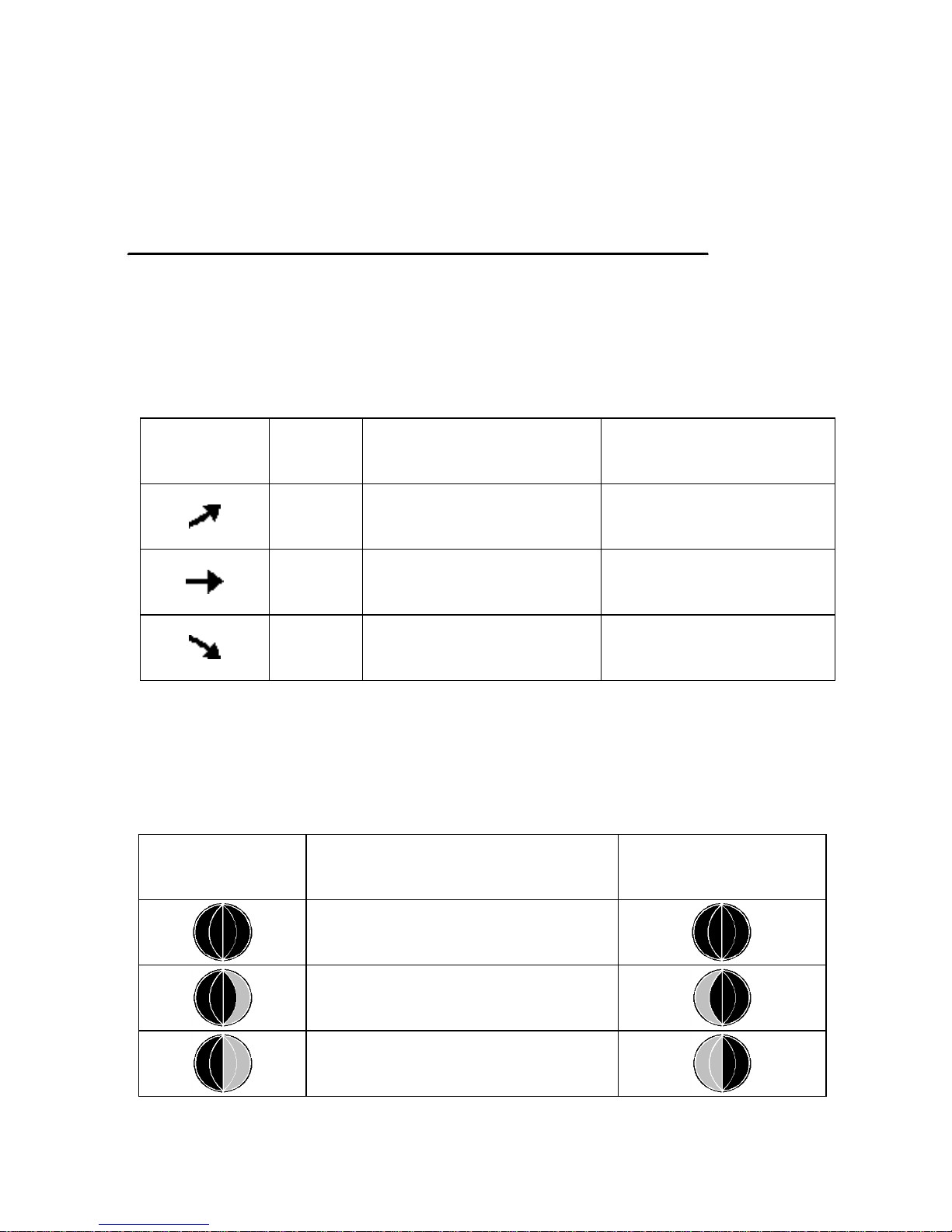
Weather Tendency indicators
There are arrow symbols besides the indoor/outdoor temperature and
humidity segments to indicate weather trend:
Tendency
indicators
Humidity
Temperature
Rising
Rising rate >= 10%
within 30 minutes
Rising >= 1℃
within 30 minutes
Steady
Change rate < 10%
within 30 minutes
Change rate < 1℃
within 30 minutes
Falling
Falling rate >= 10%
within 30 minutes
Falling >= 1℃
within 30 minutes
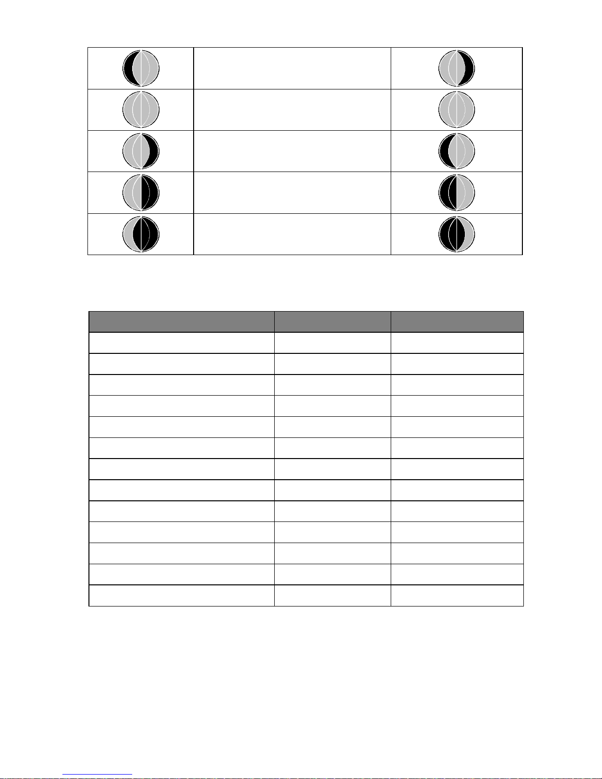
Moon Phases
Make sure to program your console’s North/South Hemisphere setting
(Page 21-22)
Icon: Northern
Hemisphere
Moon Phase Description
Icon: Southern
Hemisphere
NEW MOON
WAXING CRESCENT MOON
FIRST QUARTER MOON
Page 28
8000060 Rev 3 19-Feb-19 TyconSystems.com
28
WAXING GIBBOUS MOON
FULL MOON
WANING GIBBOUS MOON
LAST QUARTER MOON
WANING CRESCENT MOON
Beaufort Scales (Wind Speed)
Wind speed
Beaufort number
Description
0-1mph(0-1.6kph)
0
Calm
1-3mph(1.6-4.8kph)
1
Light air
3-7mph(4.8-11.3kph)
2
Light breeze
7-12mph(11.3-19.3kph)
3
Gentle breeze
12-18mph(19.3-29.0kph)
4
Moderate breeze
18-24mph(29.0-38.6kph)
5
Fresh breeze
24-31mph(38.6-49.9kph)
6
Strong breeze
31-38mph(49.9-61.2kph)
7
Near gale
38-46mph(61.2-74.1kph)
8
Gale
46-54mph(74.1-86.9kph)
9
Strong gale
55-63mph(88.5-101.4kph)
10
Storm
64-73mph(103-117.5kph)
11
Violent storm
74mph or above(119.1kph)
12
Hurricane
Page 29

8000060 Rev 3 19-Feb-19 TyconSystems.com
29
Specification
Outdoor data
Transmission distance in open field : 100m(330 feet)
Frequency : 433MHZ
Temperature range : -40˚C--60˚C (-40℉ to +140℉)
Accuracy : + / - 1 °C
Resolution : 0.1˚C
Measuring range rel. humidity : 10%~99%
Accuracy : +/- 5%
Rain volume display : 0 – 9999mm (show --- if outside range)
Accuracy : + / - 10%
Resolution : 0.3mm (if rain volume < 1000mm)
1mm (if rain volume > 1000mm)
Wind speed : 0-50m/s (0~100mph) (show --- if outside range)
Accuracy : +/- 1m/s (wind speed< 5m/s)
+/-10% (wind speed > 5m/s)
UVI range : 0 to 15 index
Light : 0-200k Lux
Accuracy : +/-15%
Measuring interval outdoor sensor: 16 sec
Indoor data
Measuring interval pressure / temperature: 48 sec
Indoor temperature range : 0˚C--50˚C (14℉ to + 140℉)
(show --- if outside range)
Resolution : 0.1˚C
Measuring range rel. humidity : 10%~99%
Resolution : 1%
Page 30

8000060 Rev 3 19-Feb-19 TyconSystems.com
30
Measuring range air pressure : 300-1100hPa (8.85-32.5inHg)
Accuracy : +/-3hpa under 700-1100hPa
Resolution : 0.1hPa (0.01inHg)
Alarm duration : 120 sec
Power consumption
Base station : 5V DC adaptor (included)
Base station : 3X AA 1.5V LR6 Alkaline batteries (not included)
Remote sensor : 2X AA batteries (not included), The primary power
source is the solar panel. The batteries provide backup power when there
is limited solar energy
Note: Where the outdoor temperature is lower than -20˚C, make sure to
use Lithium Batteries. Normal alkaline batteries should not be used if the
outdoor temperature is lower than -20 ˚C, the battery’s discharging
capability is greatly reduced and the ProWeatherStation™ performance
will be affected.
Live Internet Publishing
This weather station can send data to the following free hosting services:
Hosting
Service
Website
Description
Weather
Underground
WeatherUndeground
.com
Weather Underground is a free
weather hosting service that
allows you to send and view
your weather station data
real-time, view graphs and
gauges, import text data for
more detailed analysis and use
iPhone, iPad and Android
applications available at
Wunderground.com. Weather
Underground is a subsidiary of
The Weather Channel and
IBM.
WOW
http://wow.metoffice.
gov.uk/
WOW is a UK based weather
observation website.
Page 31

8000060 Rev 3 19-Feb-19 TyconSystems.com
31
Weather
Cloud
WeatherCloud.net
Weathercloud is a real-time
weather social network formed
by observers from around the
world.
The weather station can also operate alone - showing weather data on
the display console and computer (only if the weather station console and
computer are connected to the same Wi-Fi). It doesn’t require an internet
connection to operate in this mode.
Android Software Operation
Connecting the Weather Station Console to Wi-Fi
To send weather data to these services you must connect your console to
the internet via Wi-Fi. The console can only operate using Wi-Fi when the
external power adapter is connected and plugged in!
Note: If you are testing the setup with the outdoor sensor package
nearby and indoor, you may want to consider connecting to Wi-Fi,
but not yet configuring any of the weather services. The reason is
that while indoor the temperatures and humidity recorded by the
outdoor sensor, and as reported to the weather service(s) will
reflect indoor conditions and not outdoor conditions. Therefore,
they will be incorrect. Furthermore, the rainfall bucket may be
tripped during handling, causing rain to register while it may not
actually have been raining. One way to prevent this is to follow all
instructions, except to use an incorrect password on purpose!
Then, after the final outdoor installation, come back and change
the password after clearing console history. That will start
uploading to the services with a clean slate.
Download mobile application
Wi-Fi configuration is done using your mobile. Start by downloading the
“WS View” application from the Google Play store.
Page 32
8000060 Rev 3 19-Feb-19 TyconSystems.com
32
Connect the console to Wi-Fi (Android)
1.1 Android user:
Now activate the application you have downloaded on your mobile
device. The following instructions will generally show screenshots for the
Android application side by side.
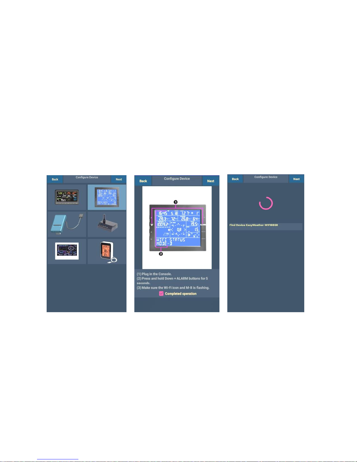
Configure Device
Note: If you own a dual band router (2.4 GHz and 5.0 GHz), make sure
you connect to the 2.4 GHz band, otherwise the Weather Station will fail
connecting to Wi-Fi.
1)
Select the device
you have from the
device list, then
press Next
2)
Operate as per the
information, tick the box
to confirm “completed
operation”, press Next.
3)
The app would then search
for the ProWeatherStation
console:
The device named
“EasyWeather-WI-FI”
followed by four
characters.
Page 33
8000060 Rev 3 19-Feb-19 TyconSystems.com
33
Upload Setting
Your console can send your sensor data to select internet-based weather
services: Wunderground.com, Weathercloud.net and,
WeatherObservationsWebsite. Users need to register at their preferred
website to get a station ID and password. These steps are optional, you
don’t have to register to each site to get the ProWeatherStation to work. If
you choose not to upload data right now, press the Back button.
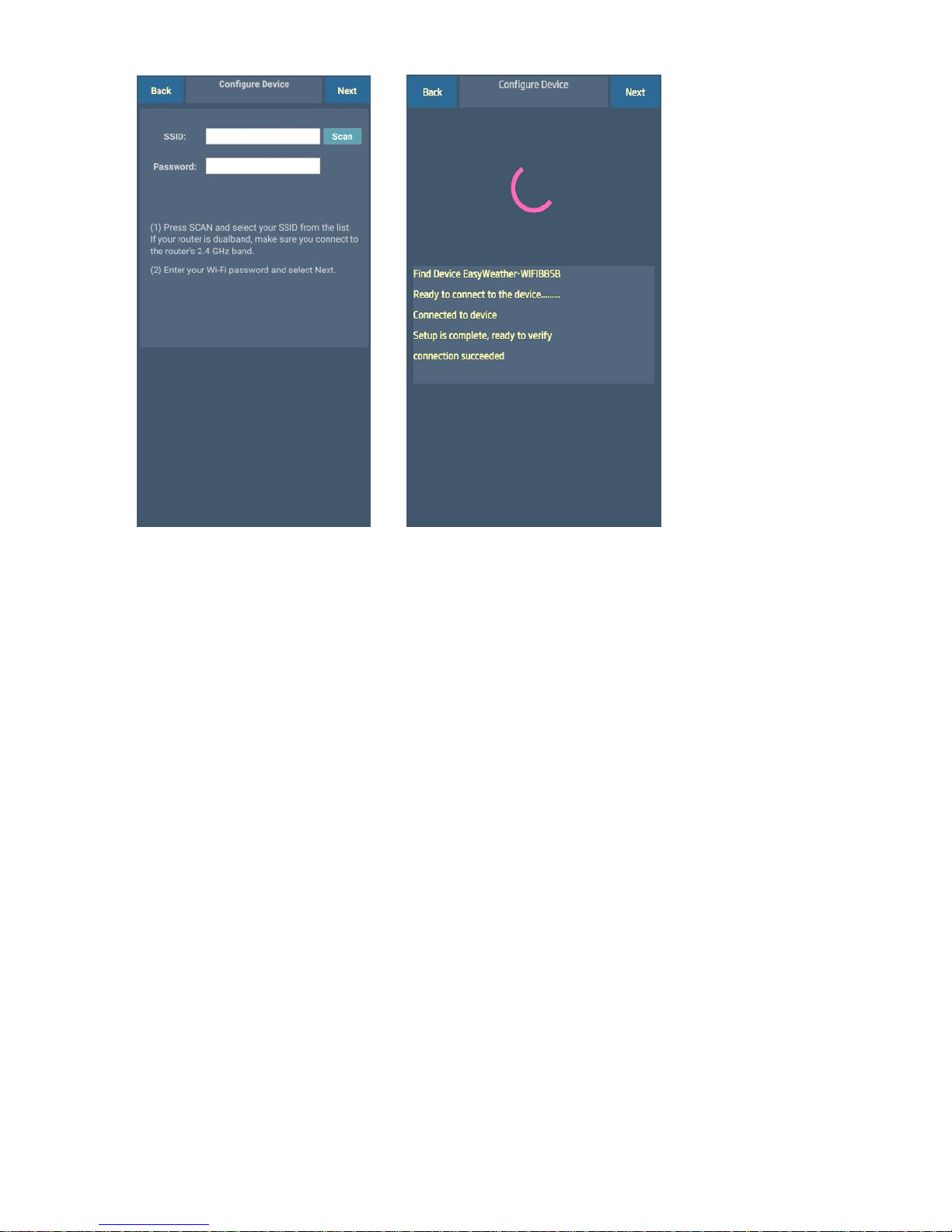
5)
The app will then connect
your ProWeatherStation to
your Wi-Fi. If configured
successfully it will jump to
“Upload Setting” screen
automatically. If the
configuration fails, make sure
the Wi-Fi icon and Mode-B is
flashing and you are putting
in the correct SSID and
password.
4)
Press Scan and select the
Wi-Fi network you would like
the console to connect to, you
may also type in the SSID
and password, and press
Next
Note: SSID and passwords
are case sensitive. Make sure
you connect to a 2.4GHz
band.
Page 34
8000060 Rev 3 19-Feb-19 TyconSystems.com
34
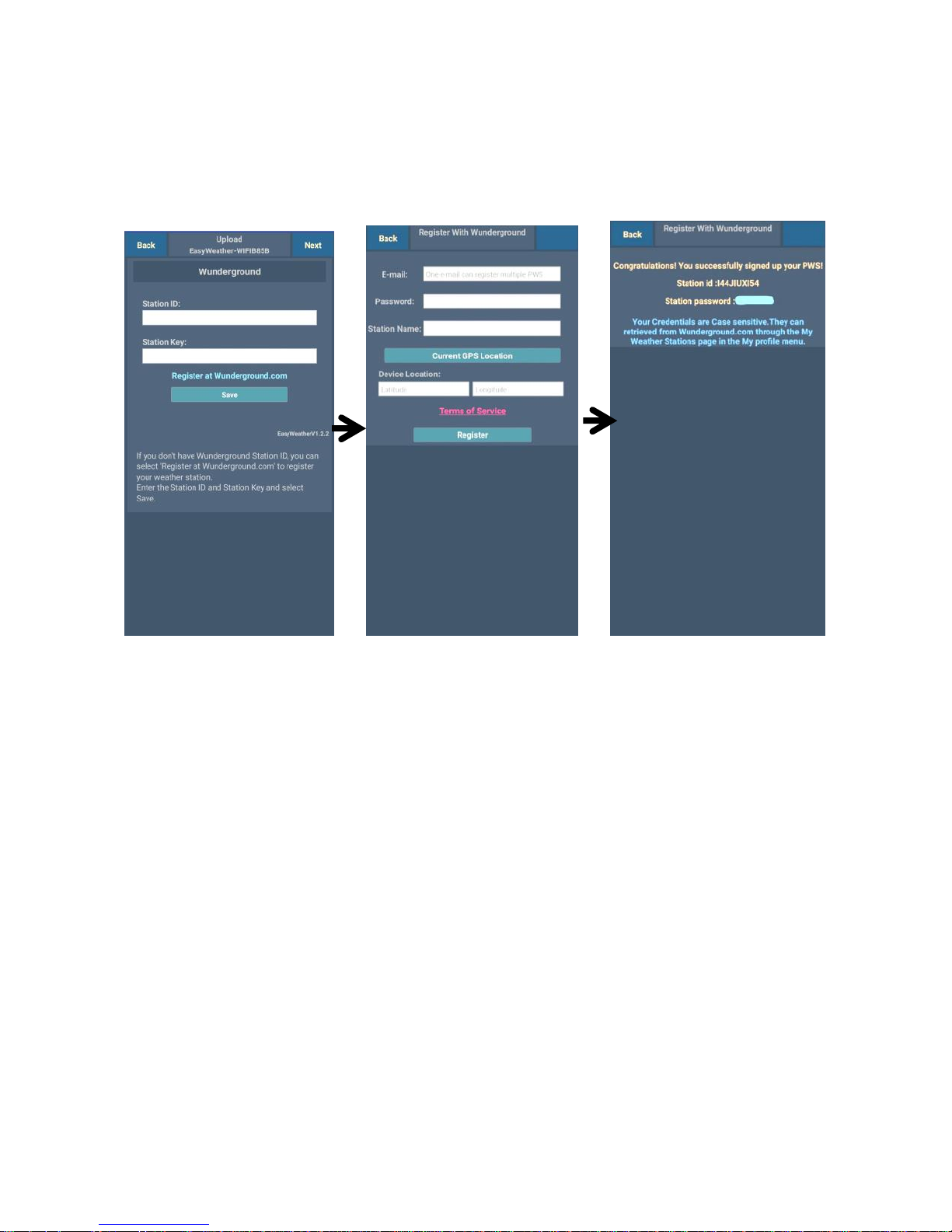
Note:Users can register to Wunderground.com directly through the WS
View App, Weathercloud and WOW through a web browser
a. Upload your weather data to Wunderground.com
1)
Upload your weather data
to Wunderground.com
Input Station ID & Station
Key, press Save. Your
station ID will be added on
the WU StationID.
then press Next.
Jump to the screen about
Upload your weather data
to Weathercloud.net
If you don’t have a
Wunderground Station ID
and Key, press “Register
at Wunderground.com”
to Register with
Wunderground.
2)
Register at
Wunderground.com
Enter your valid e-mail
address and
password to obtain the
Station ID & Station
Key from
Wunderground.com.
Enter the Station
Name you want.
Press “Current GPS
Location” to get the
device current location
of Latitude and
Longitude.
Then press Register
3)
If registered
successfully, you’ll
receive a Station ID
and Station password /
key. You will also
receive an e-mail about
the information of
Station ID and Station
password / key
Then press Back to
return to the Upload
screen
Page 35
8000060 Rev 3 19-Feb-19 TyconSystems.com
35
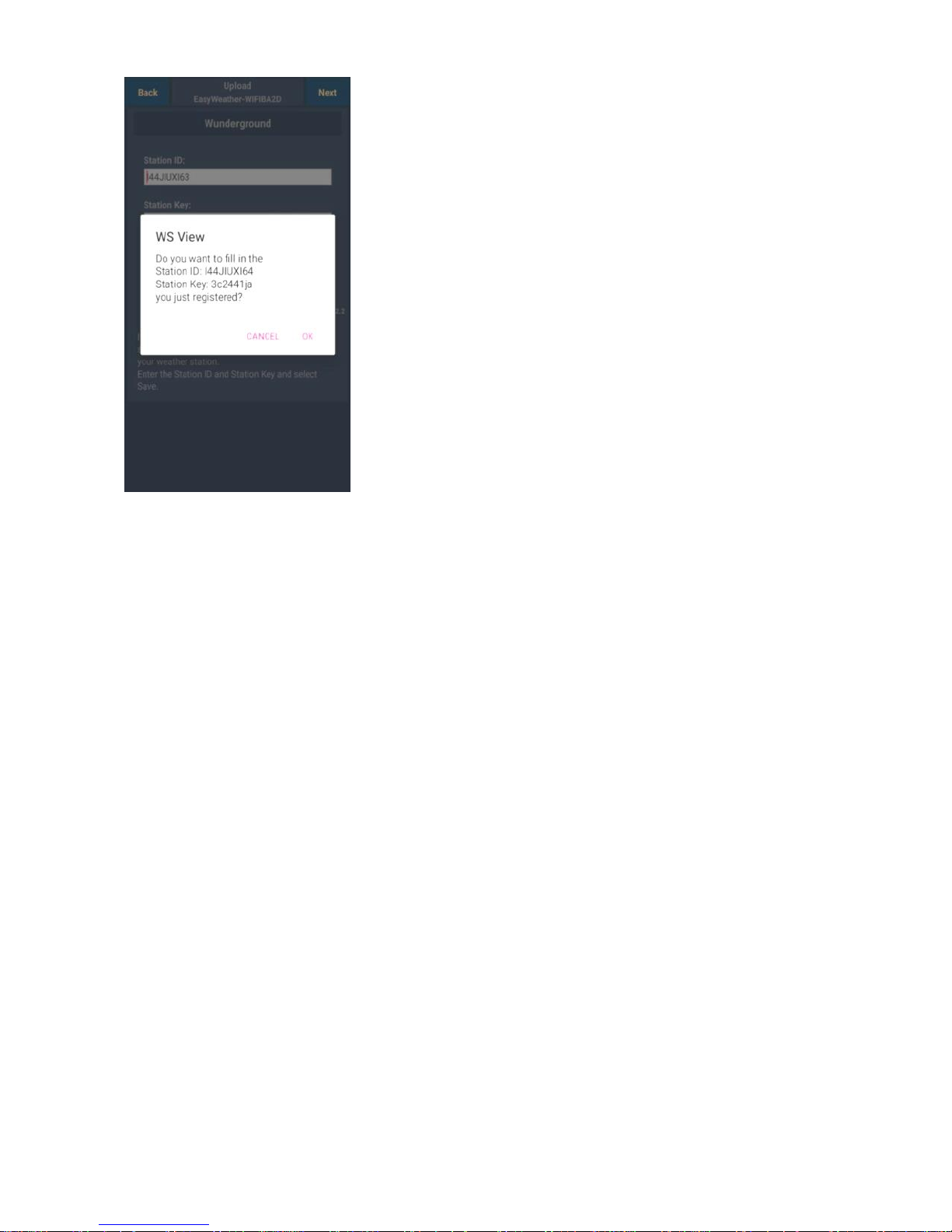
4)
Select OK to fill in the Station
ID and Station password / key
automatically.
Press Save Your station ID
will be added on the WU
StationID. Upload to
Wunderground.com Setting
finish.
Press Next. Jump to the
screen about Upload your
weather data to
Weathercloud.net
Press Back if you don’t want
to upload the data to another
website.
Page 36
8000060 Rev 3 19-Feb-19 TyconSystems.com
36
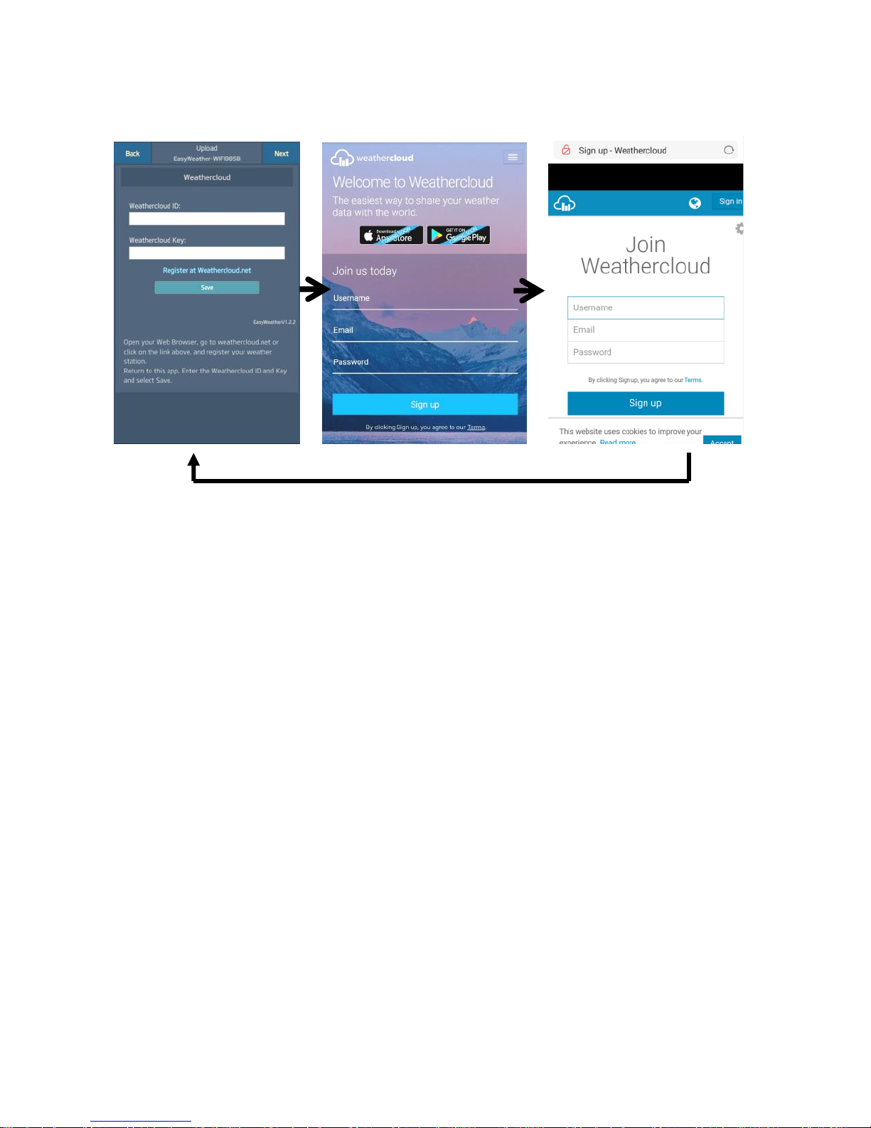
b. Upload your weather data to Weathercloud.net
1)
Upload your weather data to
Weathercloud.net
Input Weathercloud ID &
Weathercloud Key, press
Save then press Next.
If you don’t have
Weathercloud ID and Key,
press “Register at
Weathercloud.net”
2)
Register at
Weathercloud.net
Visit
weathercloud.net and
enter a Username,
Email and Password
to sign up
Respond to the
validation email from
Weathercloud (it may
take a few minutes)
3)
You will then be
prompted to add a
device/ Select “Create
device” and enter your
station’s information.
Select Fine Offset as
the manufacturer and
WH Series as the
Model. Select WS Tool
as the Link Type. Fill in
other information as
needed
After registering your
station, take note of the
“Weathercloud ID” and
“Key” presented to you.
Enter these values in
the mobile application
and press Save
Page 37
8000060 Rev 3 19-Feb-19 TyconSystems.com
37
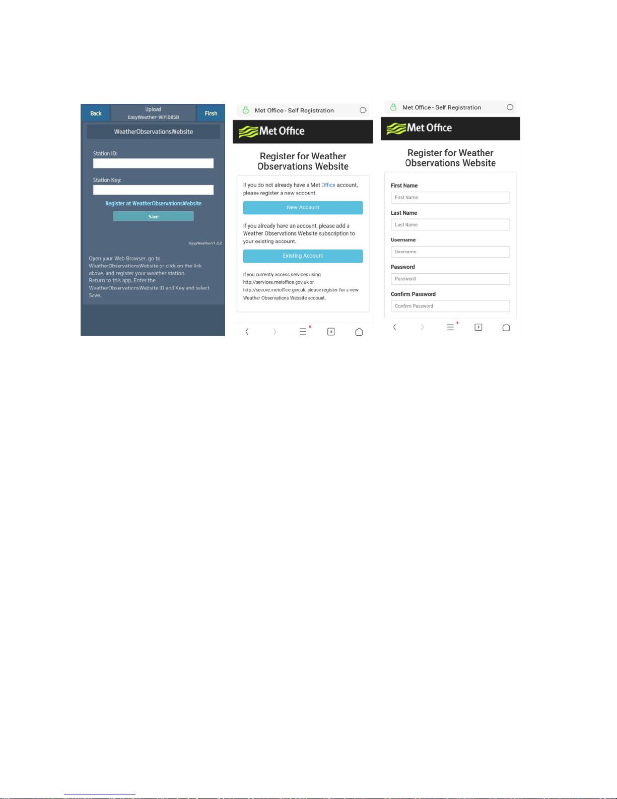
c. Upload your weather data to WeatherObservationsWebsite
(WOW)
1)
Upload your weather data to
WOW
Input Weathercloud ID &
Weathercloud Key, press
Save.
then press Finish. Jump to
the Device List home
screen
If you don’t have WOW ID
and Key, press “Register at
WeatherObservationsWebsi
te”.
2)
Register at
WeatherObservationsW
ebsite
Choose “New Account”
you will be presented with
a form to fill out
3)
The actual form is
longer, but all questions
should be
self-explanatory.
Complete and submit
the form. You will shortly
receive an email with
instructions on how to
log in
Now wait for the email to
arrive and click the link
in that email to confirm
your email address.
Page 38
8000060 Rev 3 19-Feb-19 TyconSystems.com
38
Follow instructions on the screen and log in to the site
Once you are logged in you will need to create a new WOW site. “Sites”
are the means by which WOW organizes weather data you contribute.
Basically, WOW builds a personal web site for your weather station.
Associated with the web site are two items you will need to allow
uploading of data:
Site ID: This is an arbitrary number that is used to distinguish your site
from another. This number appears (in brackets) next to or underneath the
name of your site on the site information page, for example:
6a571450-df53-e611-9401-0003ff5987fd
Authentication Key: This is a 6-digit number that is used to ensure data
is coming from you and not another user.
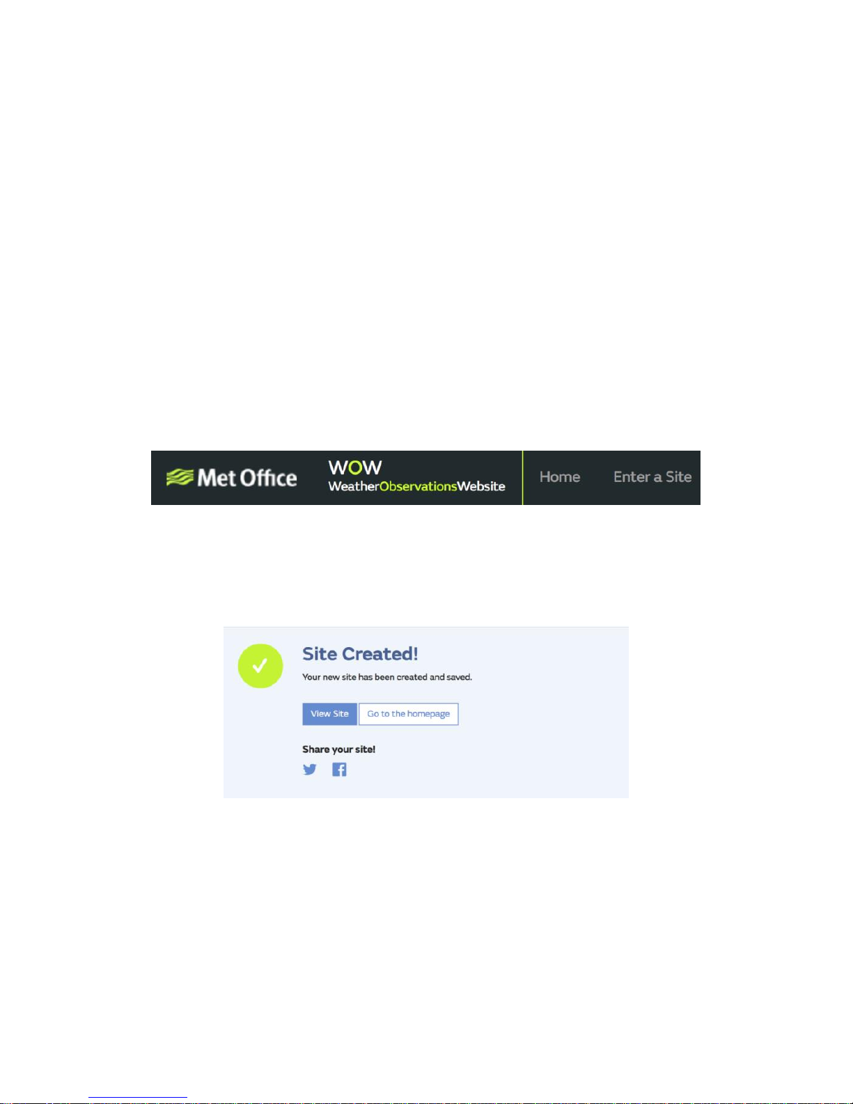
Begin setting up a new site by clicking “Enter a Site”:
You will be presented with a form where you detail your station’s location
and a bunch of other settings related to how you wish the site to operate.
After you complete the setup, you should see:
Make sure you are (still) logged in to the WOW site. Log in as necessary.
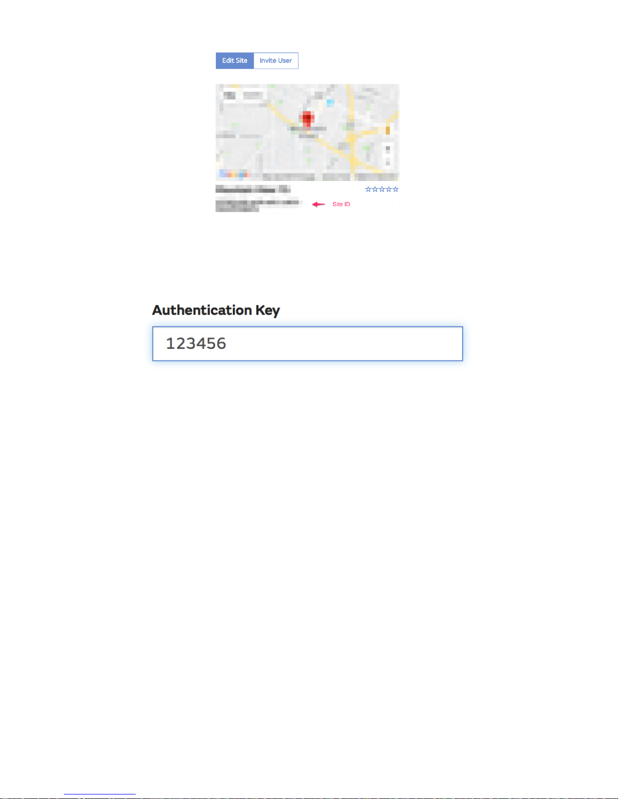
Now click on “My Sites” in the navigation bar at the top. If you have only 1
site, you will now be shown its page. If you have multiple, you will have to
choose the correct one first. On this page, you will find the site id just
below the map:
Page 39
8000060 Rev 3 19-Feb-19 TyconSystems.com
39
You will also need to establish a unique 6 digits PIN code that you should
keep secret. It is the “Authentication Key.” Set up this number by clicking
on “Edit Site”) (Error! Reference source not found.) and filling out the
with a 6-digit number of your choice:
You will need both “Site ID” and “Authentication Key” to set up the upload
configuration for WOW in the Weather Server.
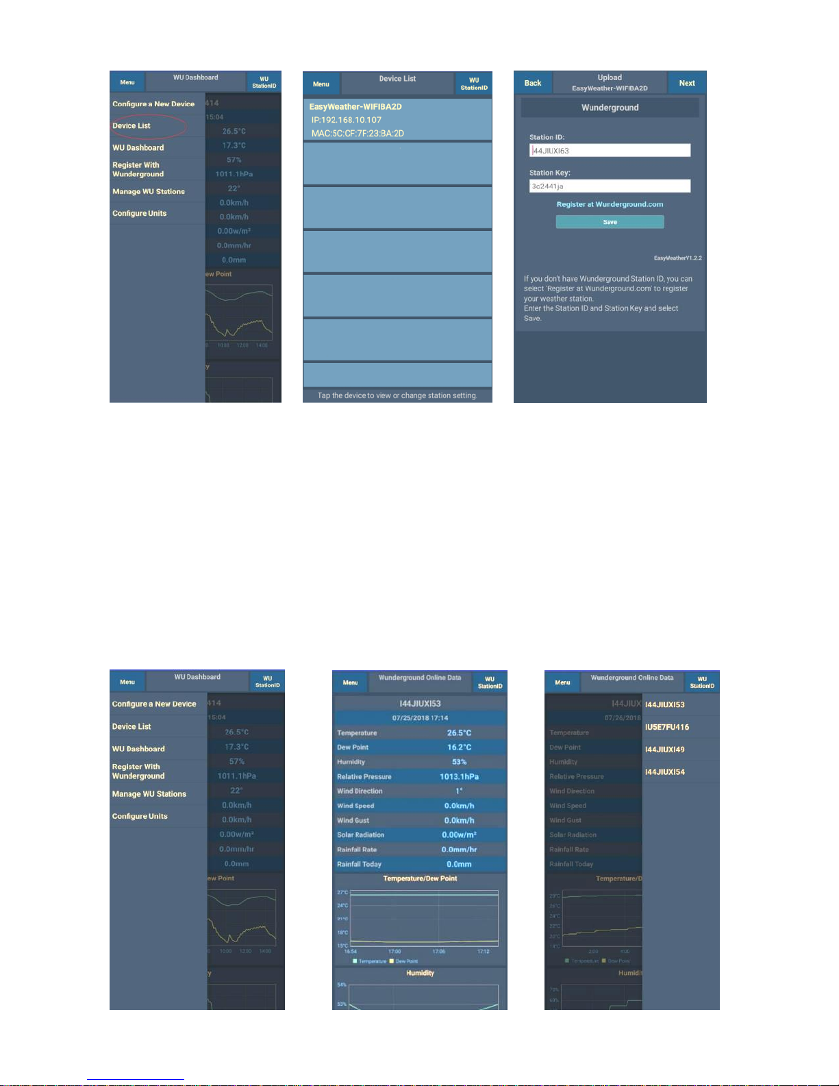
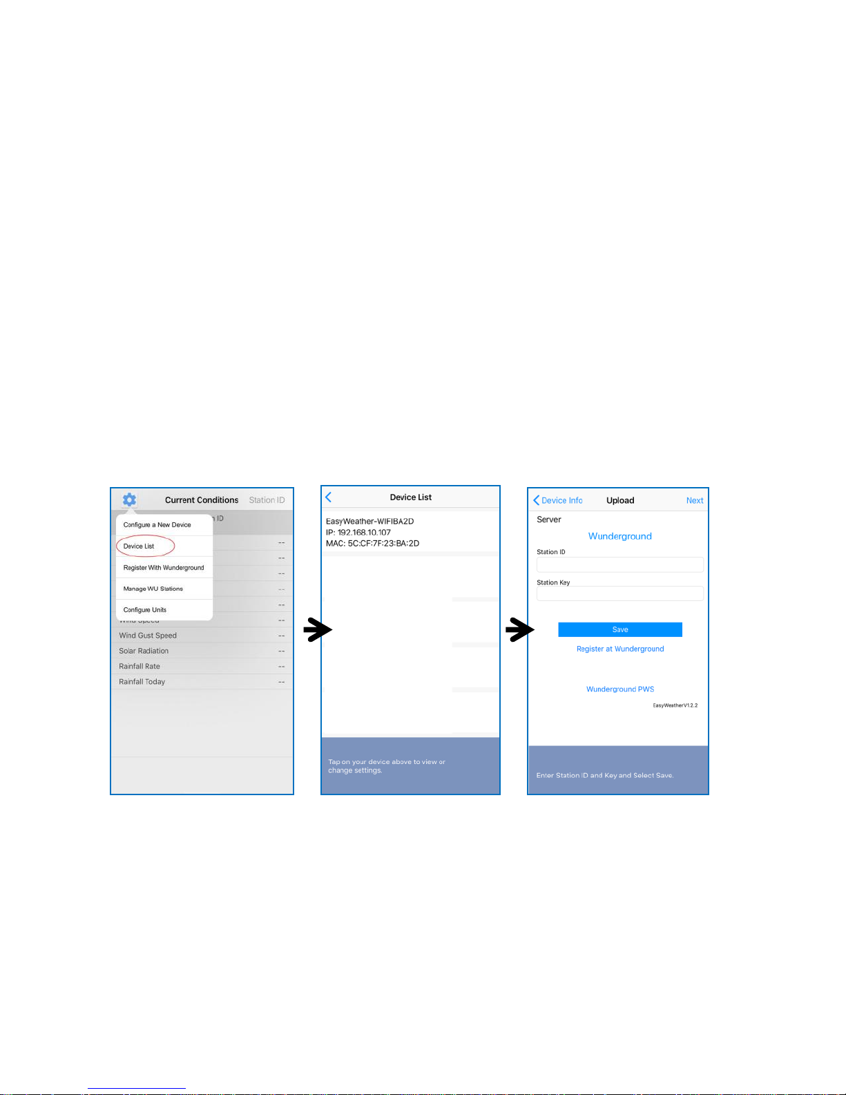
In your mobile application, navigate to the “Device List” page and tap on
the device you want to configure WOW for. You will then be shown the
“wunderground.com” configuration. Please ignore and tap “Next” to see
the “Weathercloud” configuration. Please press “Next” one more time and
you will now be on the screen where you will configure WOW.
On this screen, you will fill out “Station ID” with the WOW “Site ID” value,
and “Station Key” with the WOW “Authentication Key” you created. Press
“Save” to finalize the configuration.
Mobile application – Device list
You can see your console through the “Device List” menu option:
Tapping on your console’s entry in the device list will bring you to the page
where you can change WU registration information. If you want to stop
your console upload data to Wunderground, delete your Station ID and
select “Save”.
Page 40
8000060 Rev 3 19-Feb-19 TyconSystems.com
40
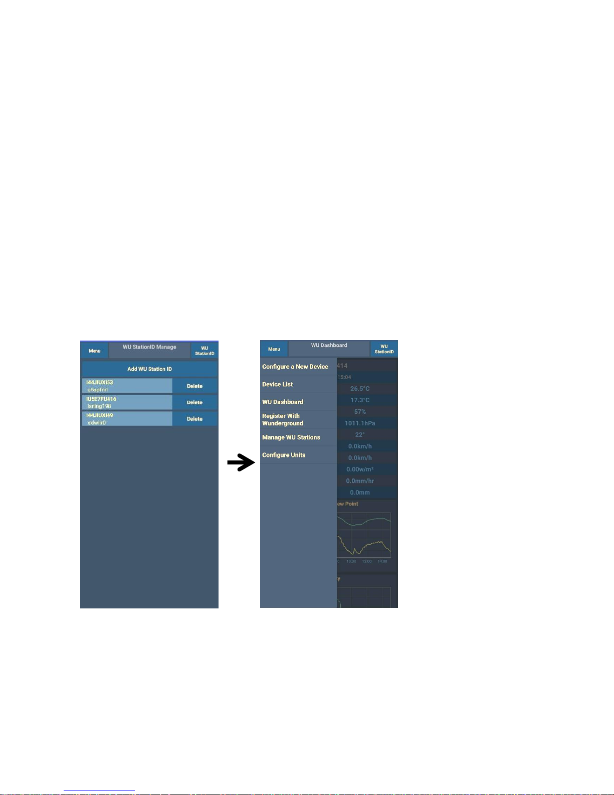
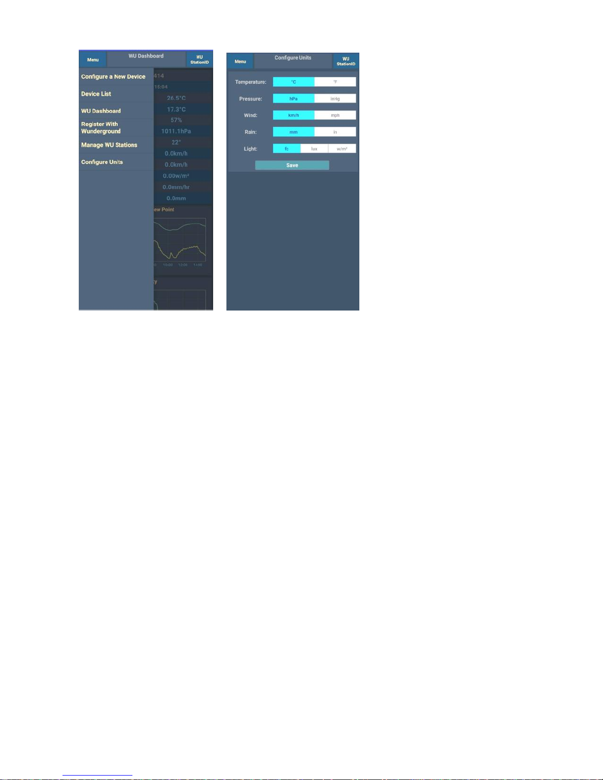
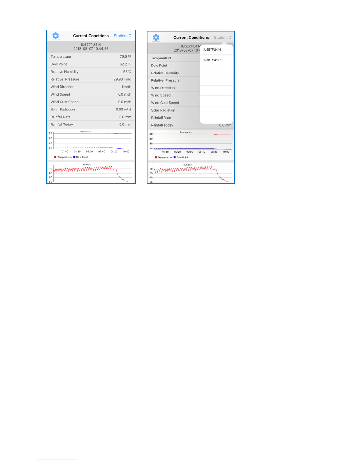
Mobile application – Check WU weather data and graph
In the mobile application tap Menu choose WU Dashboard and you will
be presented with a page listing current conditions for that station.
If you have added multiple WU IDs, tap on the WU Station ID to switch to
view data from other IDs.
Page 41
8000060 Rev 3 19-Feb-19 TyconSystems.com
41
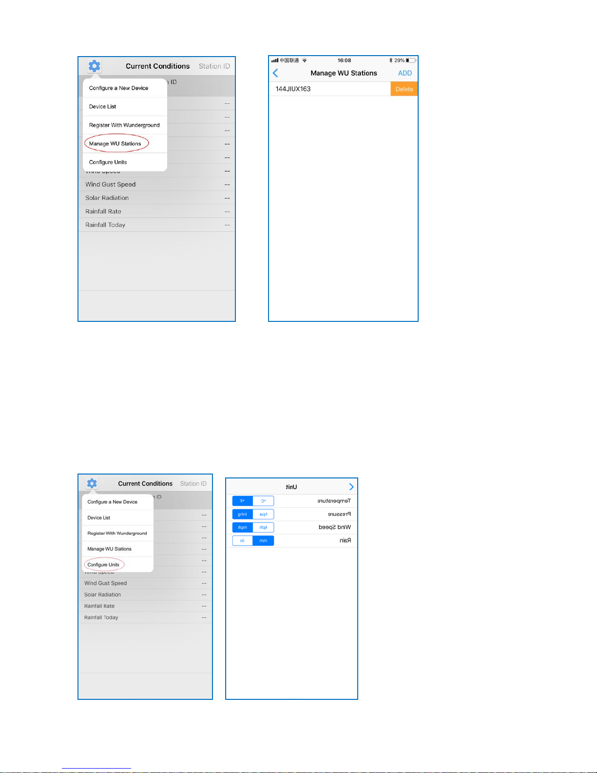
Mobile application – Remove or Add WU ID
If you have previously registered your console for use with
wunderground.com and wish to remove this device data display from App,
use the “Manage WU Station” menu option after tapping on the settings
icon, select “Delete” your console from the list and confirm you wish to
delete the station. The Station ID will delete from WU Station ID list and
will not have the data information on the APP. But the data will upload to
Wunderground.com as usual.
If you want to add a new weather station to view its data on the APP, and
this device is registered in Wunderground.com, select “Add WU Station
ID” and input the WU station ID of this new device.
Mobile application – Set Units
You may want to change the units in which sensor values are reported. To
do so, click on the “Configure Units” menu after tapping on the settings
icon. Next, tap on the sensor type you wish to change the reporting units
for and set the units as desired.
Page 42
8000060 Rev 3 19-Feb-19 TyconSystems.com
42
iOS Software Operation
Connecting the Weather Station Console to Wi-Fi (iOS)
To send weather data to these services you must connect your console to
the internet via Wi-Fi. The console can only operate using Wi-Fi when the
external power adapter is connected and plugged in!
Note: If you are testing the setup with the outdoor sensor package
nearby and indoor, you may want to consider connecting to Wi-Fi,
but not yet configuring any of the weather services. The reason is
that while indoor the temperatures and humidity recorded by the
outdoor sensor, and as reported to the weather service(s) will
reflect indoor conditions and not outdoor conditions. Therefore,
they will be incorrect. Furthermore, the rainfall bucket may be
tripped during handling, causing rain to register while it may not
actually have been raining. One way to prevent this is to follow all
instructions, except to use an incorrect password on purpose!
Then, after final the outdoor installation, come back and change
the password after clearing console history. That will start
uploading to the services with a clean slate.
Page 43
8000060 Rev 3 19-Feb-19 TyconSystems.com
43
Download mobile application
Wi-Fi configuration is done using your mobile device. Start by
downloading the “WS View” application from the Apple App Store.
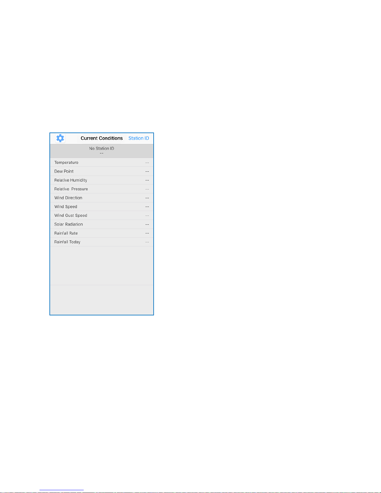
Activate the application you have downloaded on your mobile device. The
main screen will indicate your station is off-line (because it is not yet
connected to Wi-Fi).
Configure Device
Note: If you own a dual band router (2.4 GHz and 5.0 GHz), make sure
you connect to the 2.4 GHz band, otherwise it will fail to connect the
weather station to Wi-Fi.
Page 44
8000060 Rev 3 19-Feb-19 TyconSystems.com
44
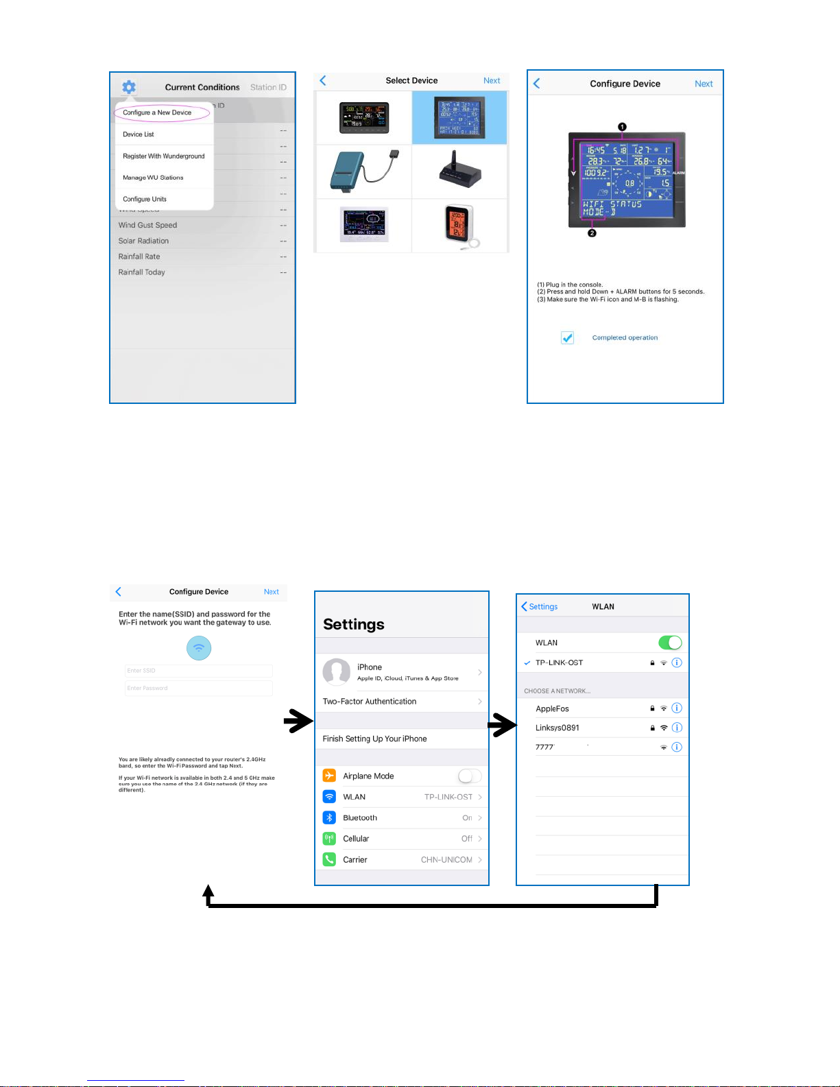
1)
Tap on the settings
icon and select
“Configure a New
Device”.
2)
Select the device you
have from the device
list, then press Next
3)
Operate as per the
information, tick the box
to confirm “completed
operation”, press Next.
4)
Enter your Wi-Fi SSID and password
and press Next.
You may also go to your Wi-Fi settings
and connect to your Wi-Fi network then
return to WS View App
Page 45
8000060 Rev 3 19-Feb-19 TyconSystems.com
45
Upload Setting
Your console can send your sensor data to select internet-based weather
services: Wunderground.com, Weathercloud.net and,
wow.metoffice.gov.uk. Users need to register at their preferred website to
get a station ID and password. These steps are optional, you don’t have
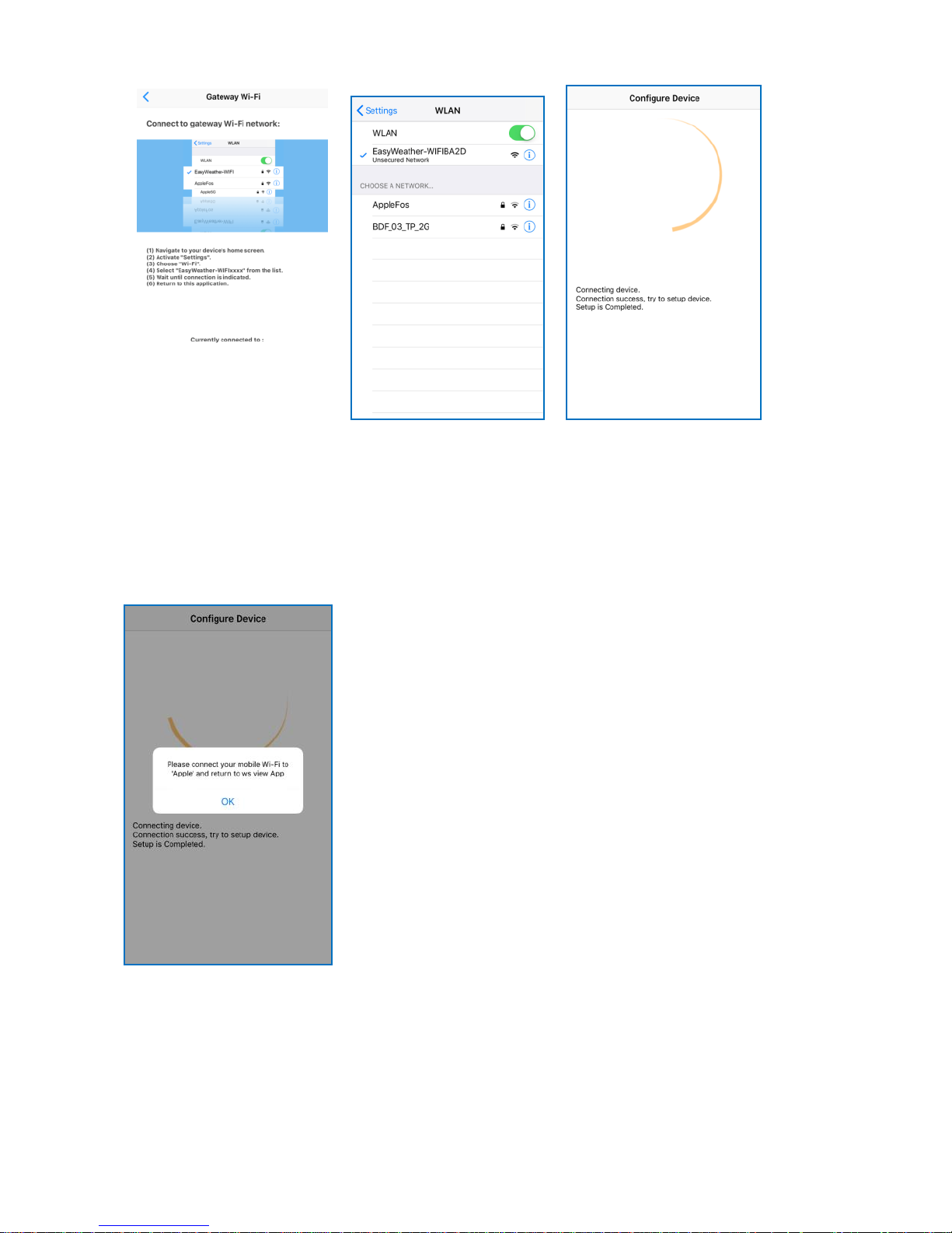
5)
Follow the instructions
as stated on the screen.
6)
Select device Wi-Fi.
The device named
“EasyWeather-WIFxx
xxI”” and return to
WS View App
7)
If the console
successfully
connects, the page
will jump to “Upload
Setting” screen
automatically.
If you see the mesage “Please connect
your mobile Wi-Fi to (Wi-Fi Network
name) and return to WS View App”. Go
back to your Wi-Fi settings, connect to
your network, then switch back to the WS
View App. Press OK to continue.
Page 46
8000060 Rev 3 19-Feb-19 TyconSystems.com
46
to register to each site to get the ProWeatherStation to work. If you
choose not to upload data right now, press the Back button.
Note:Users can register to Wunderground.com directly through the WS
View App, Weathercloud and WOW through a web browser
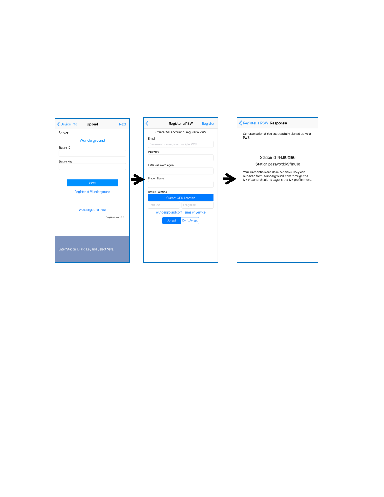
a. Upload your weather data to Wunderground.com
1)
Upload your weather data
to Wunderground.com
Input Station ID & Station
Key, press Save. Your
station ID will be added on
the WU StationID.
then press Next. Jump to
the screen about Upload
your weather data to
Weathercloud.net
If you don’t have
Wunderground Station ID
and Key, press “Register at
Wunderground.com” to
sign up for an account.
2)
Register at
Wunderground.com
Enter your valid e-mail
address and password
to obtain the Station ID &
Station Key from
Wunderground.com.
Enter the Station Name
you want. Press
“Current GPS Location”
to get the device current
location of Latitude and
Longitude.
Then press Register
3)
If registered successfully,
you’ll receive a Station ID
and Station password /
key. You will also receive
an e-mail about the
information of Station ID
and Station password /
key
Then return to Upload
Wunderground screen to
input Station ID & Station
Key.
Page 47
8000060 Rev 3 19-Feb-19 TyconSystems.com
47
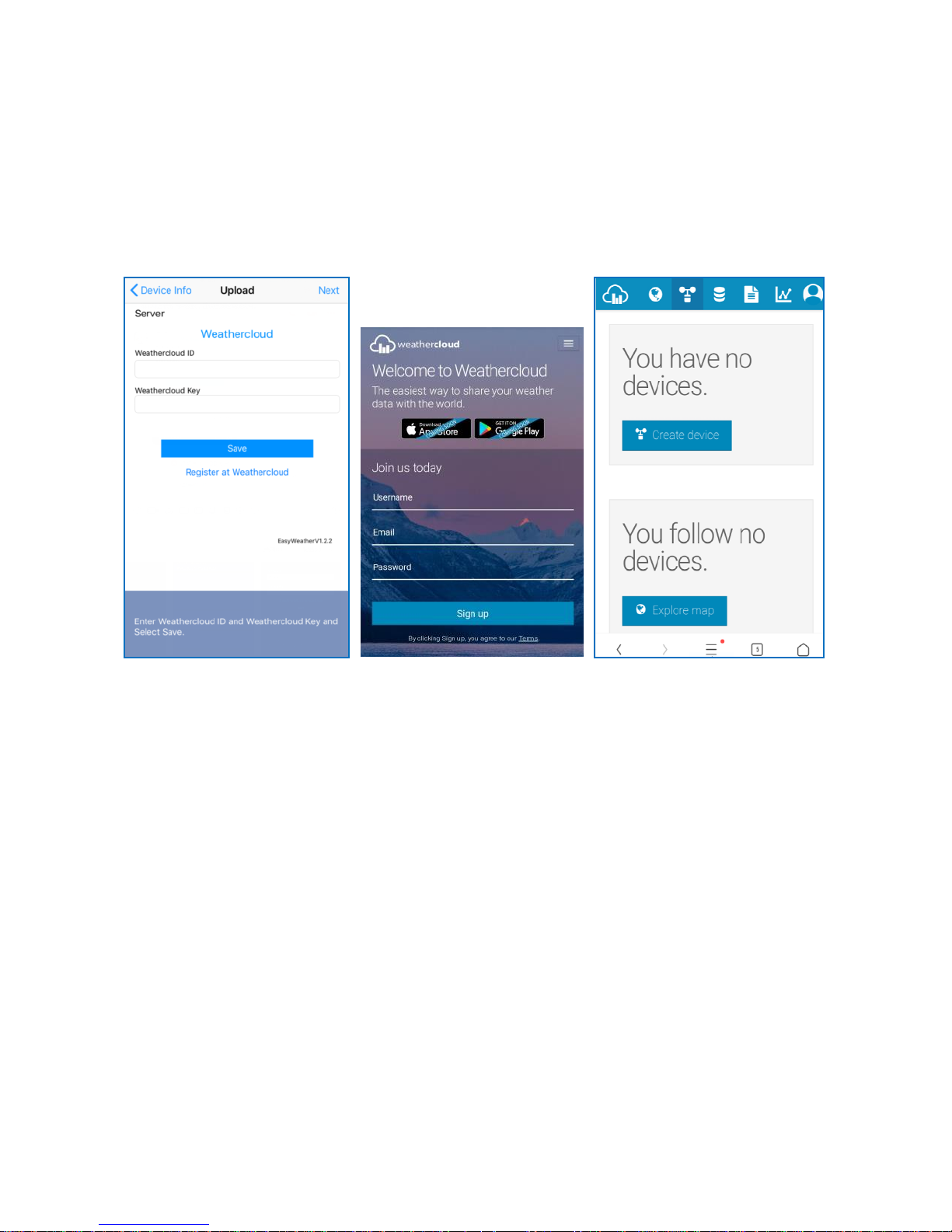
b. Upload your weather data to Weathercloud.net
Input Weathercloud ID & Weathercloud Key, press Save. Then press
Next.
If you don’t have a Weathercloud ID and Key, press “Register at
Weathercloud.net” to open a web browser, then sign up.
You will then be prompted to add a device/ Select “Create device” and
enter your station’s information. Select Fine Offset as the manufacturer
and WH Series as the Model. Select WS Tool as the Link Type. Fill in
other information as needed
After registering your station, take note of the “Weathercloud ID” and
“Key” presented to you.
Go back to the app and input your Weathercloud press Save. Then press
Next.
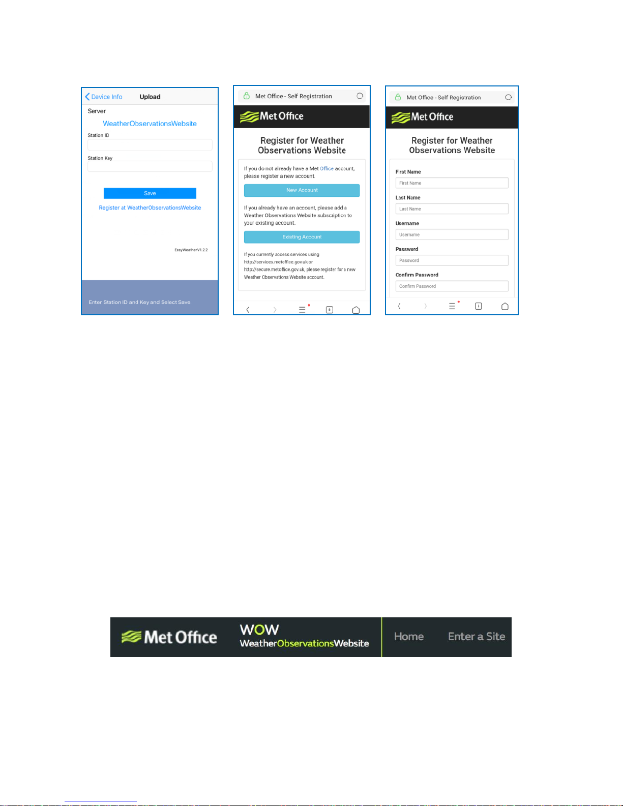
c. Upload your weather data to WeatherObservationsWebsite
(WOW)
Input WOW Station ID and Key, press Save. Then press Finish.
Page 48
8000060 Rev 3 19-Feb-19 TyconSystems.com
48
If you don’t have a WOW ID and Key, press “Register at
WeatherObservationsWebsite” to open a web browser, then sign up.
Follow instructions on the screen and log in to the site
Once you are logged in you will need to create a new WOW site. “Sites”
are the means by which WOW organizes weather data you contribute.
Basically, WOW builds a personal web site for your weather station.
Associated with the web site are two items you will need to allow
uploading of data:
Site ID: This is an arbitrary number that is used to distinguish your site
from another. This number appears (in brackets) next to or underneath the
name of your site on the site information page, for example:
6a571450-df53-e611-9401-0003ff5987fd
Authentication Key: This is a 6-digit number that is used to ensure data
is coming from you and not another user.
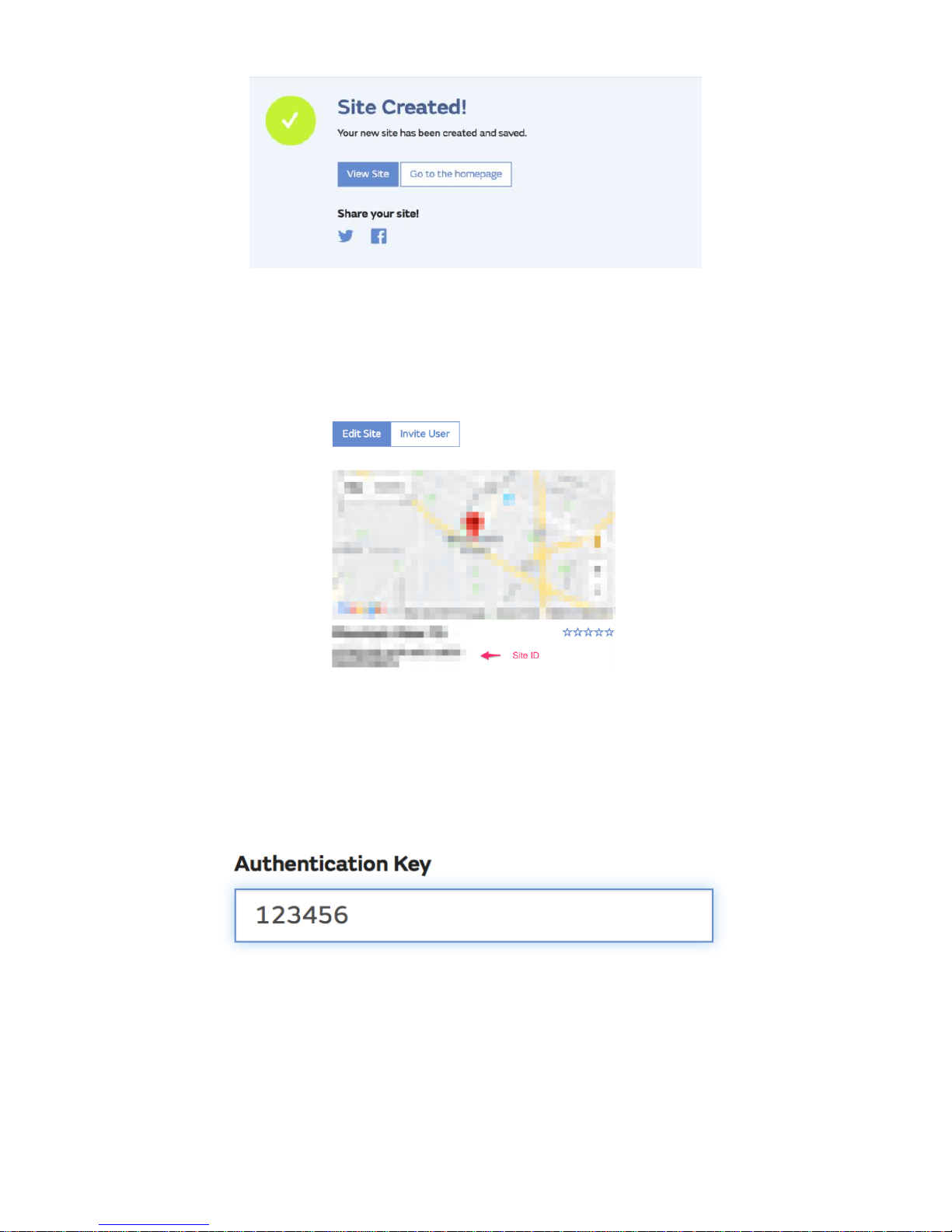
Begin setting up a new site by clicking “Enter a Site”:
You will be presented with a form where you detail your station’s location
and a bunch of other settings related to how you wish the site to operate.
After you complete the setup, you should see:
Page 49
8000060 Rev 3 19-Feb-19 TyconSystems.com
49
Make sure you are (still) logged in to the WOW site. Log in as necessary.
Now click on “My Sites” in the navigation bar at the top. If you have only 1
site, you will now be shown its page. If you have multiple, you will have to
choose the correct one first. On this page, you will find the site id just
below the map:
You will also need to establish a unique 6 digits PIN code that you should
keep secret. It is the “Authentication Key.” Set up this number by clicking
on “Edit Site”) (Error! Reference source not found.) and filling out the
with a 6-digit number of your choice:
You will need both “Site ID” and “Authentication Key” to set up the upload
configuration for WOW in the Weather Server.
In your mobile application, navigate to the “Device List” page and tap on
the device you want to configure WOW for. You will then be shown the
“wunderground.com” configuration. Please ignore and tap “Next” to see
Page 50
8000060 Rev 3 19-Feb-19 TyconSystems.com
50
the “Weathercloud” configuration. Please press “Next” one more time and
you will now be on the screen where you will configure WOW.
On this screen, you will fill out “Station ID” with the WOW “Site ID” value,
and “Station Key” with the WOW “Authentication Key” you created. Press
“Save” to finalize the configuration.
Mobile application – Device list
You can see your console through the “Device List” menu option:
Tapping on your console’s entry in the device list will bring you to the page
where you can change WU registration information. If you want to stop
your console upload data to Wunderground, delete your Station ID and
select “Save”.
Mobile application – Check WU weather data and graph
In the mobile application tap Menu choose WU Dashboard and you will
be presented with a page listing current conditions for that station.
If you have added multiple WU IDs, tap on the WU Station ID to switch to
view data from other IDs.
Page 51
8000060 Rev 3 19-Feb-19 TyconSystems.com
51
Mobile application – Remove or Add WU ID
If you have previously registered your console for use with
wunderground.com and wish to remove this device data display from App,
use the “Manage WU Station” menu option after tapping on the settings
icon, select “Delete” your console from the list and confirm you wish to
delete the station. The Station ID will delete from WU Station ID list and
will not have the data information on the APP. But the data will upload to
Wunderground.com as usual.
If you want to add a new weather station to view its data on the APP and
this device is registered in Wunderground.com, select “Add WU Station
ID” and input the WU station ID of this new device.
Page 52
8000060 Rev 3 19-Feb-19 TyconSystems.com
52
Mobile application – Set Units
You may want to change the units in which sensor values are reported. To
do so, click on the “Configure Units” menu after tapping on the settings
icon. Next, tap on the sensor type you wish to change the reporting units
for and set the units as desired.
Page 53
8000060 Rev 3 19-Feb-19 TyconSystems.com
53
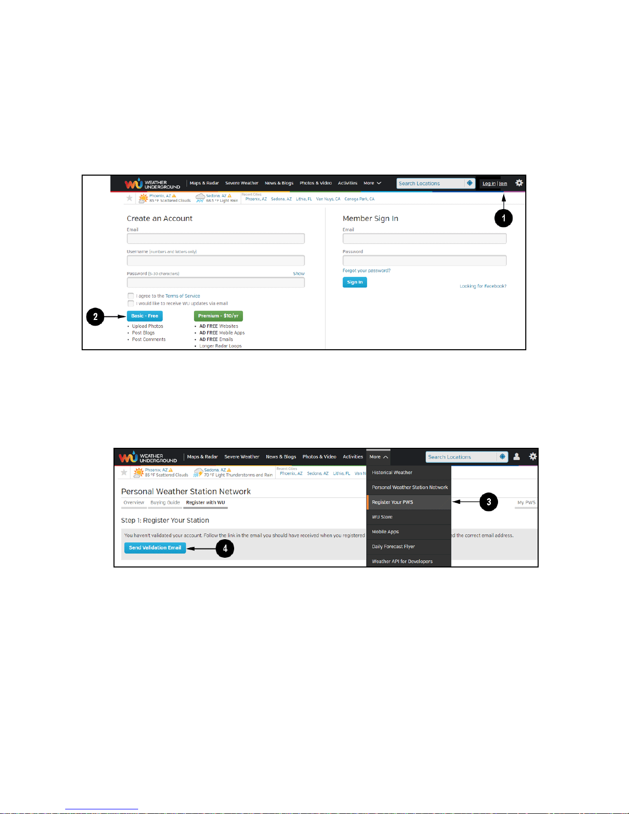
Registering with WeatherUnderground.com through a PC
or Mac.
1. Visit Wunderground.com and select the Join link at the top of the page.
Select the Free sign up option.
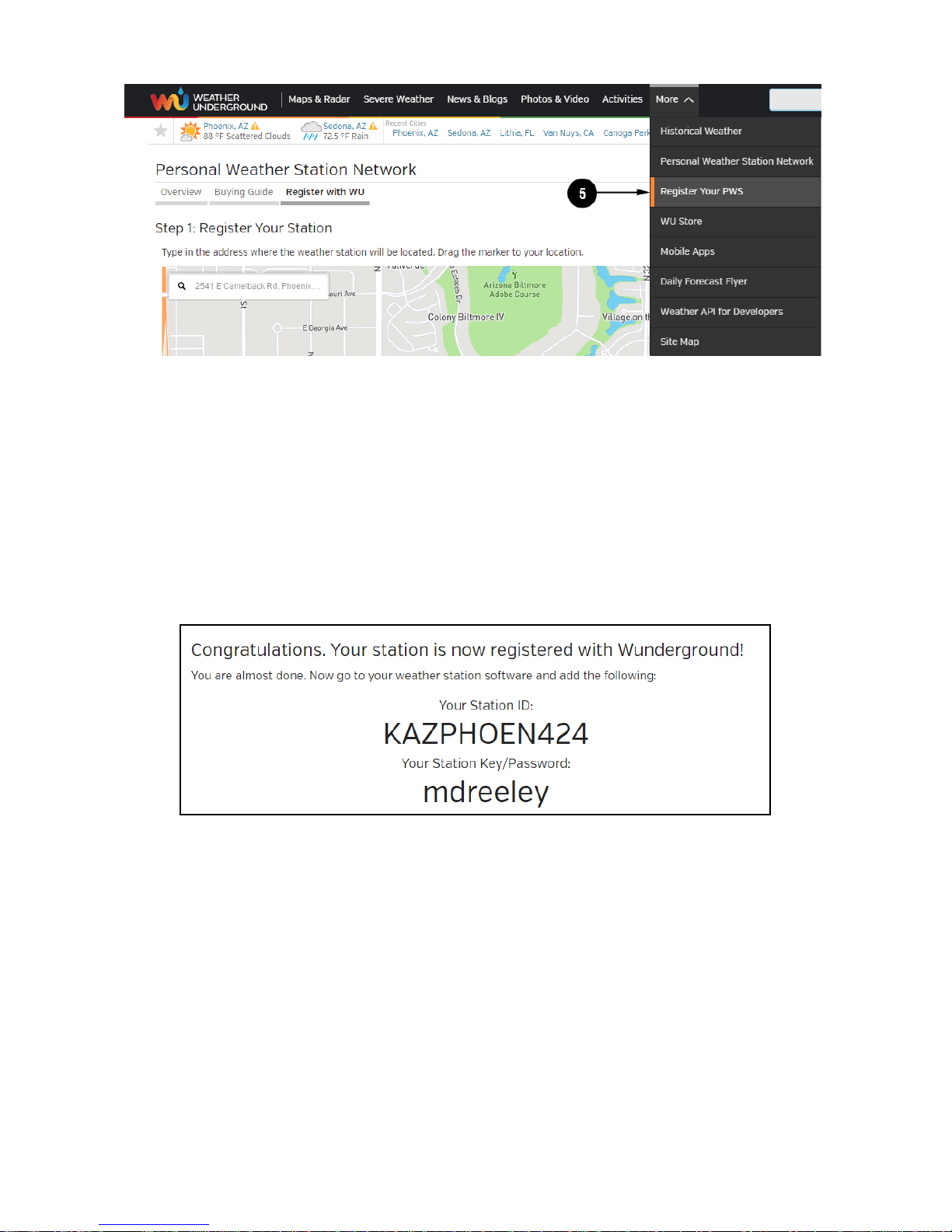
2. Select More | Register Your PWS.
3. Click Send Validation Email. Respond to the validation email from
Wunderground (it may take a few minutes).
4. Select More | Register Your PWS again and enter all the information
requested.
Page 54
8000060 Rev 3 19-Feb-19 TyconSystems.com
54
5. After registering your station, make a note of the following:
• Station ID
• Station Key / Password
Enter the Station ID (ID) and Station Key (Password) into the WS View.
Next image is an example (Your station ID and password will be different)
Note: Your station ID will have the form: KSSCCCC###, where K is for
USA station (I for international), SS is your state, CCCC is your city and
### is the station number in that city.
In the example above, KAZPHOEN424 is in the USA (K), State of Arizona
(AZ), City of Phoenix (PHOEN) and #424.
Viewing your Data on Wunderground.com
Page 55
8000060 Rev 3 19-Feb-19 TyconSystems.com
55
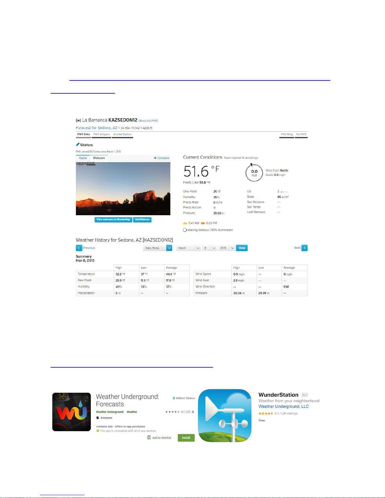
There are several ways to view your data on Wunderground:
Web Browser
Visit:http://www.wunderground.com/personal-weather-station/dashboard
?ID=STATIONID where STATIONID is your personal station ID (example,
KAZSEDON12).
Mobile Apps
Download the mobile app and sign in. Visit:
https://www.wunderground.com/download for a complete list of Mobile
apps for iOS and Android.
Page 56
8000060 Rev 3 19-Feb-19 TyconSystems.com
56
Registering and Viewing your Data on WeatherCloud.net
through a PC or Mac
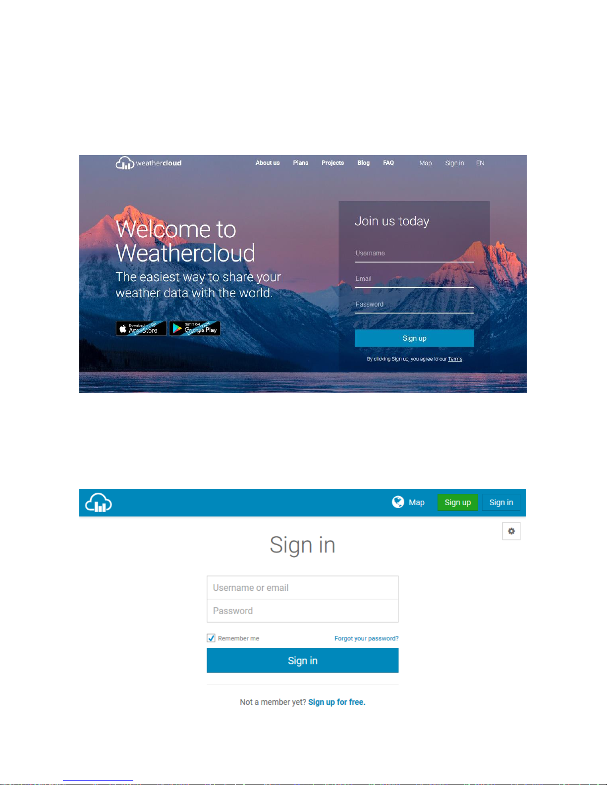
1. Visit WeatherCloud.net and enter a Username, Email, and
Password.
2. Verify your account by clicking on the link contained in the email
from WeatherCloud (it may take a few minutes).
3. Sign in to your account https://app.weathercloud.net/signin
Page 57
8000060 Rev 3 19-Feb-19 TyconSystems.com
57
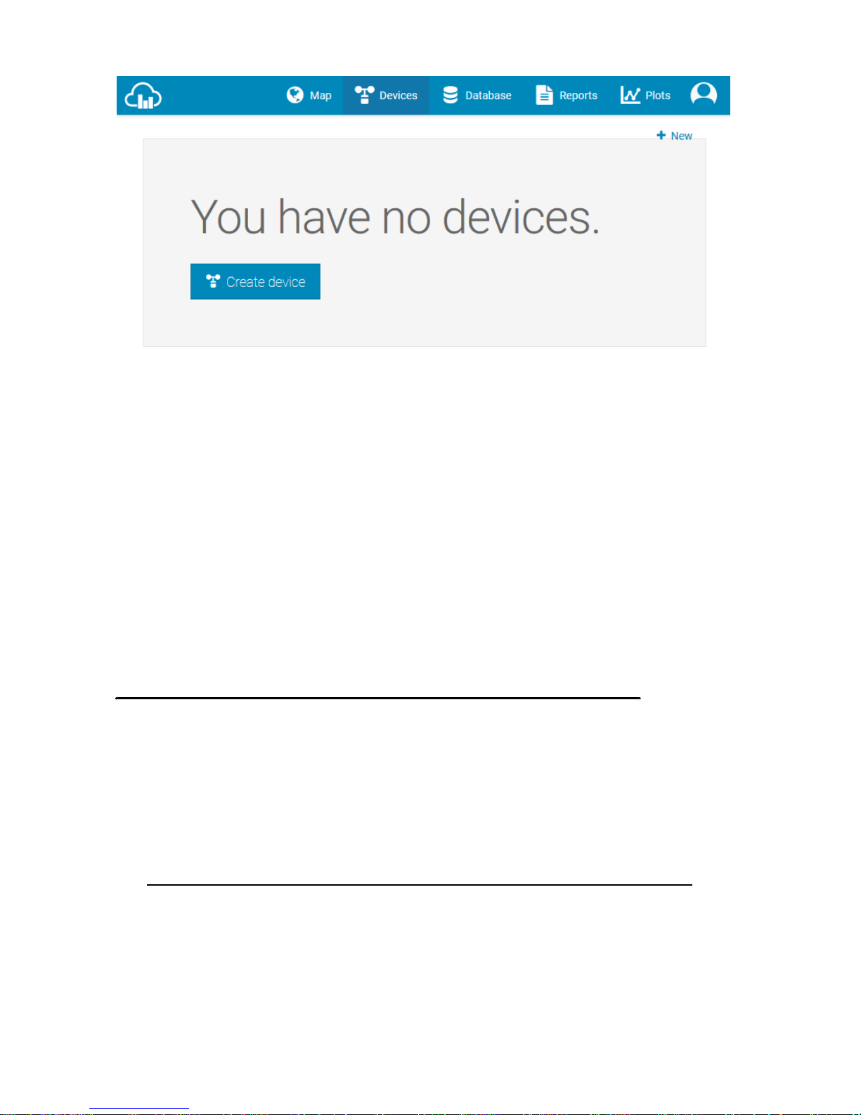
4. Select Create Device and enter your weather station information.
Select Fine Offset as the manufacturer and WH Series as the
Model. Select WS Tool as the Link Type. Fill in other information
as needed. After registering your station, take note of the
Weathercloud ID and Key
Enter the Weathercloud ID (ID), Key (password) into the WS View app.
PC Software Operation
The ProWeatherStation™ includes a PC software to adjust the settings
and monitor the readings.
Connect the display console with the PC software:
1. Download and install the PC software from
http://download.ecowitt.net/down/softwave?n=WeatherSmartIP
2. Make sure your PC is in the same network (connected via Wi-Fi or
Ethernet) as the Weather Station console. Connect your console to
your Wi-Fi network by following the instructions in this user guide
(Page 31 for Android, 43 for iOS).
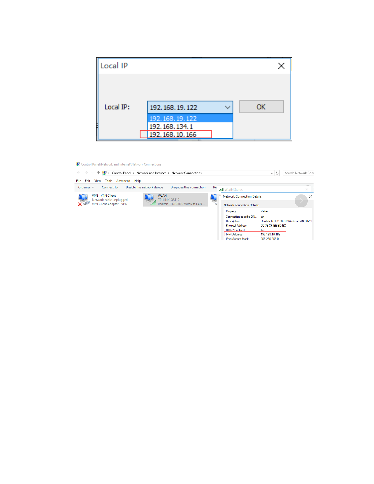
3. Launch the software and select the IP address of your PC (check the
Page 58
8000060 Rev 3 19-Feb-19 TyconSystems.com
58
properties of the Wi-Fi network on your computer to find the IP
address) and click OK.
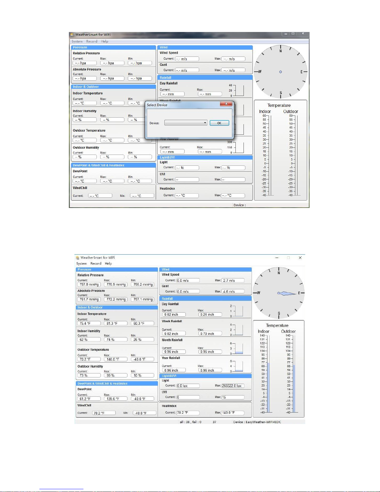
4. Under System column, click Select Device and choose weather
station device IP address (weather station display IP address can be
found on Device List from your WS View app). Click OK.
Page 59
8000060 Rev 3 19-Feb-19 TyconSystems.com
59
5. PC will try to connect to weather station now.
6. When connected successfully the weather data from the console will
show.
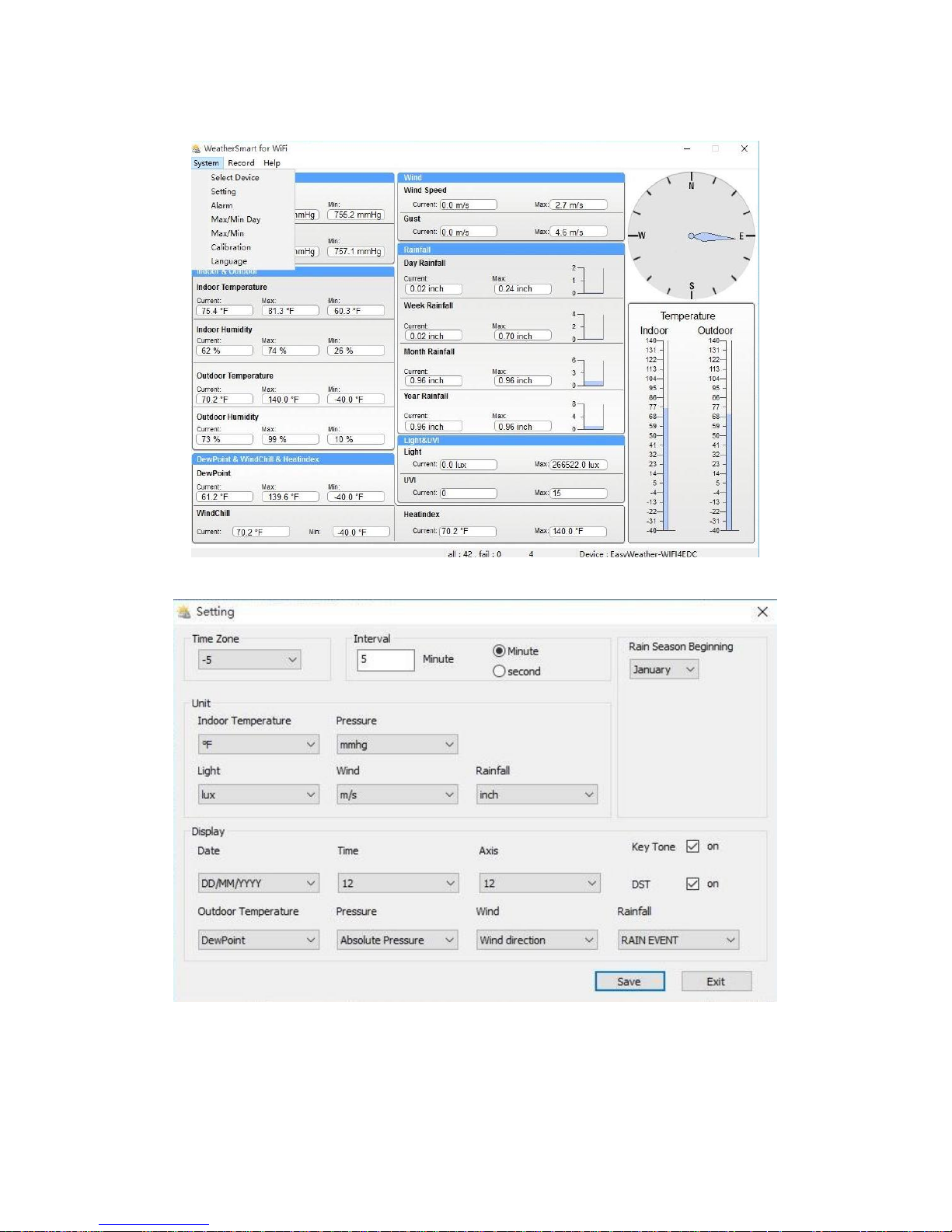
Basic Functions of the "WeatherSmartIP" Software
Page 60
8000060 Rev 3 19-Feb-19 TyconSystems.com
60
System
Setting
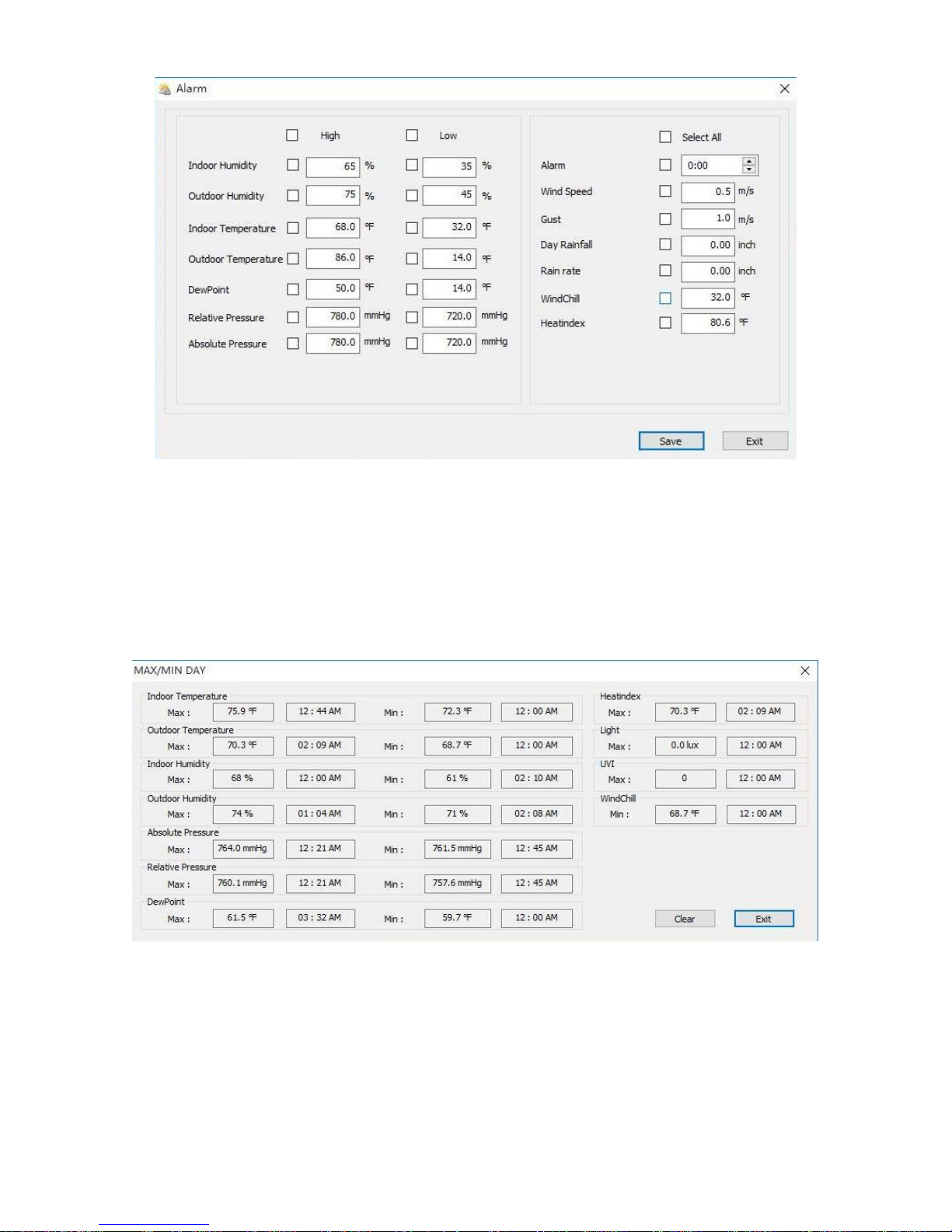
Alarm
Page 61
8000060 Rev 3 19-Feb-19 TyconSystems.com
61
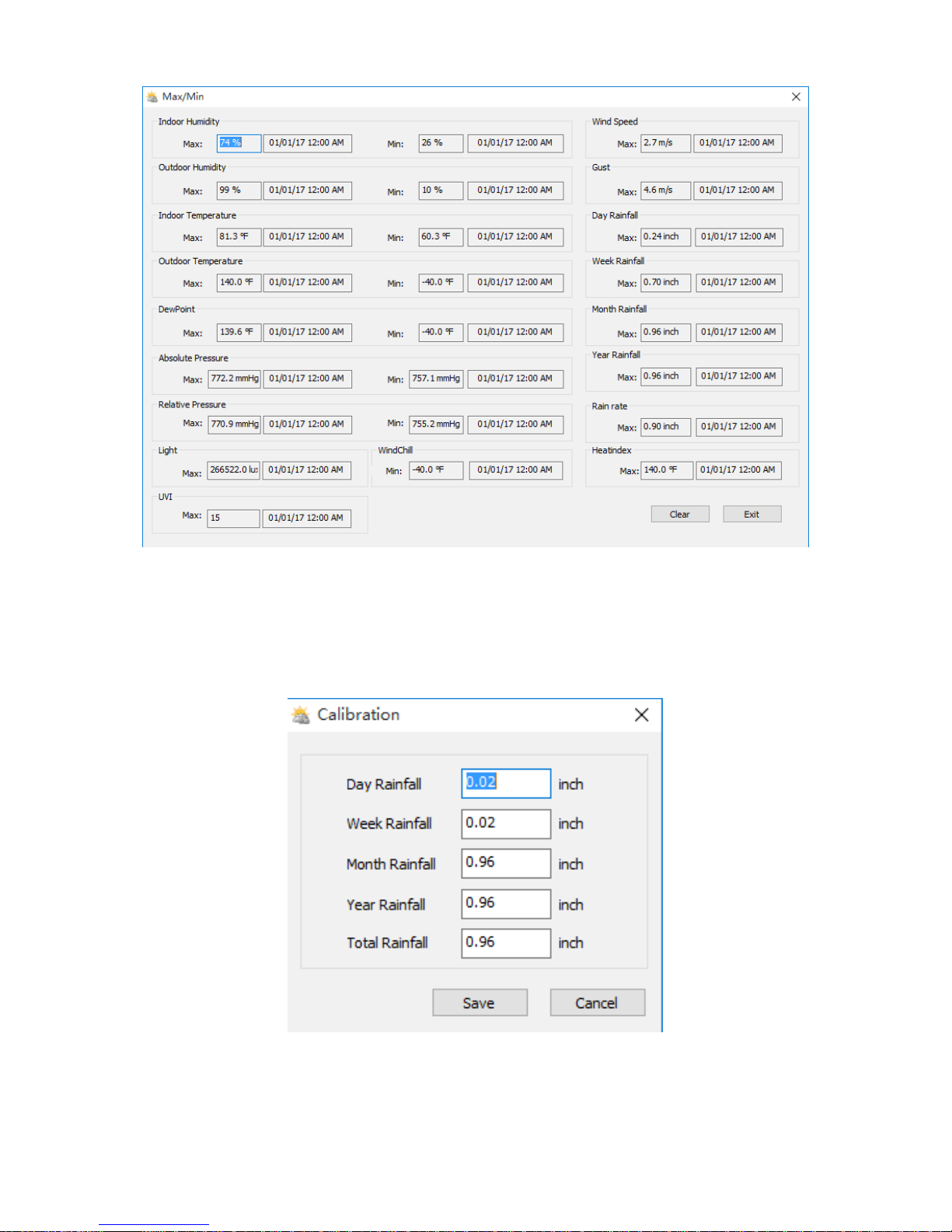
Max/Min Day
Max/Min History
Page 62
8000060 Rev 3 19-Feb-19 TyconSystems.com
62
Calibration
Page 63
8000060 Rev 3 19-Feb-19 TyconSystems.com
63
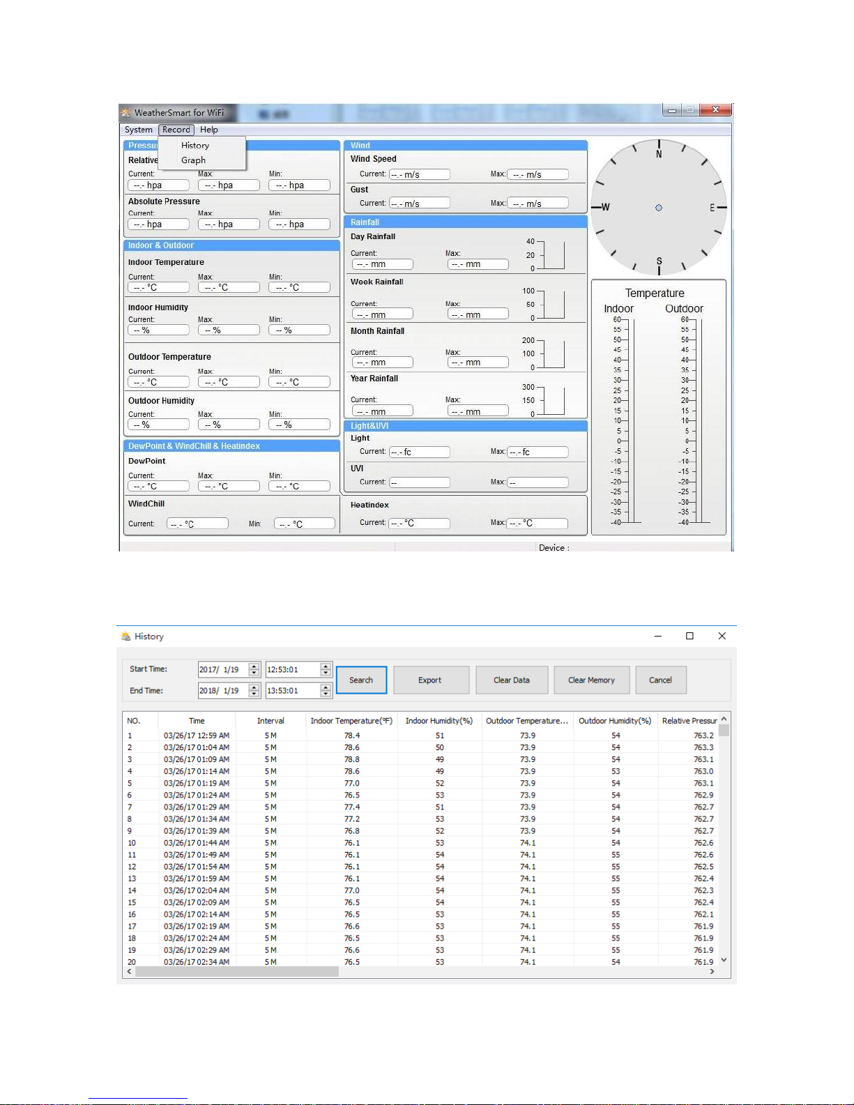
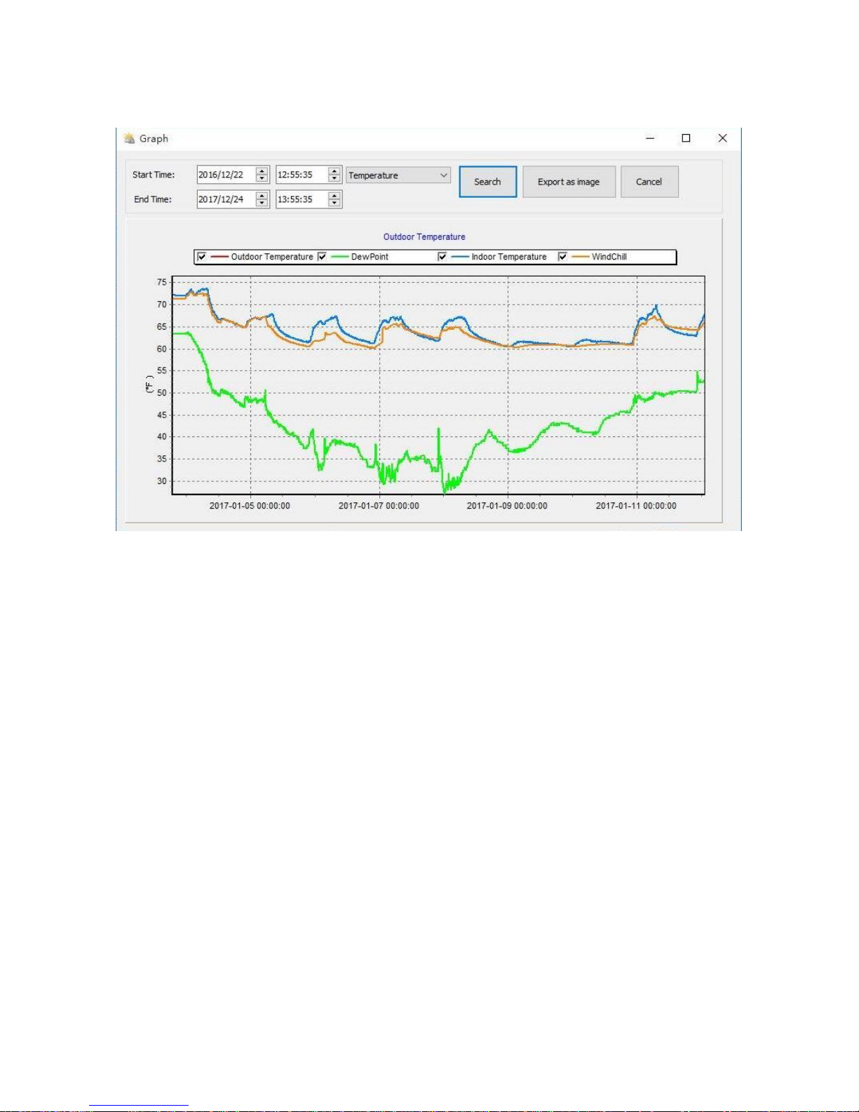
Record
History
Page 64
8000060 Rev 3 19-Feb-19 TyconSystems.com
64
Graph
Maintenance
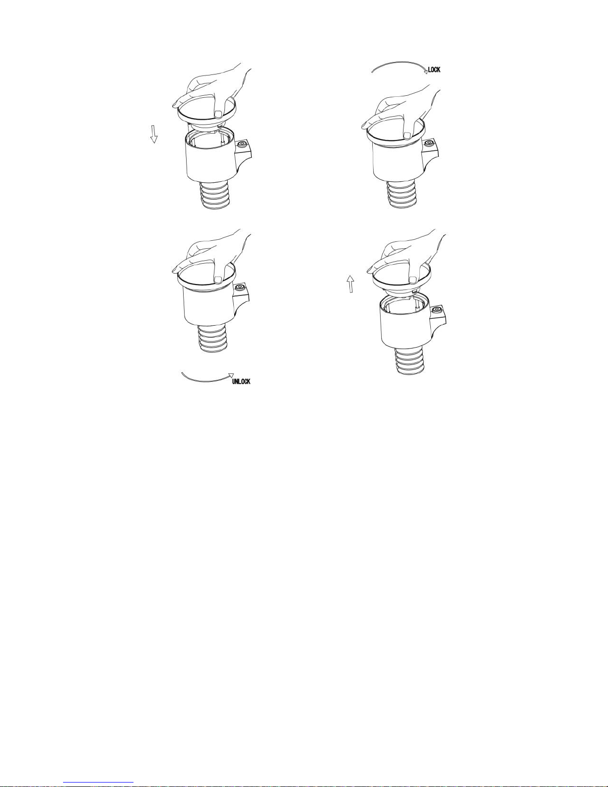
1. Clean the rain gauge once every 3 months. Rotate the funnel
counter-clockwise and lift to expose the rain gauge mechanism, and
clean with a damp cloth. Remove any dirt, debris, and insects. If bug
infestation is an issue, spray the array lightly with insecticide.
Page 65
8000060 Rev 3 19-Feb-19 TyconSystems.com
65
2. Clean the solar radiation sensor and solar panel every 3 months with
a damp cloth.
3. Replace batteries every 1-2 years. If left in too long, the batteries
may leak due to environmental challenges. In harsh environments,
inspect the batteries every 3 months (when cleaning the solar panel).
4. When replacing the batteries, apply a corrosion preventive
compound on the battery terminals, available at Amazon and most
hardware stores.
5. In snowy environments, spray the top of the weather station with
anti-icing silicon spray to prevent snow build up.
Page 66
8000060 Rev 3 19-Feb-19 TyconSystems.com
66
Troubleshooting Guide
Problem
Solution
Wireless remote
(outdoor unit) not
reporting in to console.
There are dashes (--)
on the display
console.
Check the outdoor sensor array LED for
flashing. It should flash every 16secs
The outside sensor has an LED under the
plastic, just above the battery compartment.
The LED will flash every 16 seconds.
If the LED is not flashing every 16 seconds,
Replace the batteries in the outside outdoor
sensor array.
If the batteries were recently replaced, check
the polarity. If the sensor is flashing every 16
seconds, proceed to the next step.
There may be a temporary loss of
communication due to reception loss related to
interference or other location factors, or the
batteries may have been changed in the remote
and the console has not been reset. The
solution may be as simple as powering down
and up the console.
1. Make sure you have fresh batteries
in the display console.
2. With the sensor array and console
10 feet away from each other,
remove the batteries from the
display console and wait 10
seconds. Put the batteries back in.
Page 67
8000060 Rev 3 19-Feb-19 TyconSystems.com
67
Problem
Solution
3. Do not touch any buttons for several
minutes.
4. The remote sensor search icon
will splash on the display. Wait
several minutes for this icon to turn
off.
5. If the search icon turns off and the
outdoor temperature and humidity
are still showing dashes (--), the
remote sensor is defective. If the
sensor properly syncs up, proceed
to the next step “How to prevent
intermittent wireless
communication”
How to prevent intermittent wireless
communication issues:
1. Install a fresh set of batteries in the
remote sensor array and console.
For cold weather environments,
install lithium batteries.
2. The maximum line of sight
communication range is 300’ but
most users will get 100’ or less due
to environmental conditions. Move
the sensor and remote closer
together.
3. If the sensor assembly is too close
(less than 5’), move the sensor
assembly away from the display
console.
4. Make sure the remote sensors are
Page 68
8000060 Rev 3 19-Feb-19 TyconSystems.com
68
Problem
Solution
not transmitting through solid metal
like aluminum siding (acts as an RF
shield), or earth barrier (down a hill).
5. Move the display console around
electrical noise generating devices,
such as computers, TVs and other
wireless transmitters or receivers.
6. Move the remote sensor to a higher
location. Move the remote sensor to
a closer location.
Temperature sensor
reads too high in the
day time.
Try to shade the temp/humidity sensor. Don’t
restrict airflow.
Indoor and Outdoor
Temperature do not
agree
1. Allow up to one hour for the sensors to
stabilize due to signal filtering. The
indoor and outdoor temperature
sensors should agree within 4 °F (the
sensor accuracy is ± 2 °F).
2. Perform a temperature calibration
(reference Section 2.1)
Indoor and Outdoor
Humidity do not agree
1. Allow up to one hour for the sensors to
stabilize due to signal filtering. The
indoor and outdoor humidity sensors
should agree within 10 % (the sensor
accuracy is ± 5 %)
2. Perform a humidity calibration
(reference Section 2.1)
Relative pressure
does not agree with
official reporting
station
1. You may be viewing the relative
pressure, not the absolute pressure.
2. Make sure you properly calibrate the
barometer to an official local weather
station (reference Section 2.1)
Page 69
8000060 Rev 3 19-Feb-19 TyconSystems.com
69
Problem
Solution
3. The barometer is only accurate to ±
0.08 inHg within the following relative
pressure range: 27.13 to 32.50 inHg,
which corresponds to an altitude of
-2,200 to 2,700 feet. At higher
altitudes, expect some non-linearity or
error.
Time is incorrect
Make sure your time zone and daylight savings
settings are correct.
The forecast icon is
not accurate
The weather station console must run for
several days to trend barometric pressure.
The weather forecast is an estimation or
generalization of weather changes in the next
24 to 48 hours and varies from location to
location. The tendency is simply a tool for
projecting weather conditions and is never to be
relied upon as an accurate method to predict
the weather.
Moon phase is not
correct
Check your calendar date and make sure it is
correct
Display console
contrast is weak
Replace console batteries with a fresh set of
batteries.
Data not reporting to
Wunderground.com
1. Confirm your password or key is
correct. It is the password you
registered on Wunderground.com. Your
Wunderground.com password cannot
begin with a non-alphanumeric
character (a limitation of
Wundeground.com, not the station).
Example, $oewkrf is not a valid
password, but oewkrf$ is valid.
Page 70
8000060 Rev 3 19-Feb-19 TyconSystems.com
70
Problem
Solution
2. Confirm your station ID is correct. The
station ID is all caps, and the most
common issue is substituting an O for a
0 (or vice versa). Example,
KAZPHOEN11, not KAZPH0EN11
3. Make sure the date and time are correct
on the console. If incorrect, you may be
reporting old data, not real-time data.
4. Make sure your time zone is set
properly. If incorrect, you may be
reporting old data, not real-time data.
5. Check your router firewall settings. The
console sends data via Port 80.
No Wi-Fi connection
1. Check for Wi-Fi symbol on the display.
If wireless connectivity is successful,
the Wi-Fi icon will be displayed
in the time field.
2. Make sure your modem Wi-Fi settings
are correct (network name, and
password).
3. Make sure the console is plugged into
AC power. The console will not connect
to Wi-Fi when powered by batteries
only.
Page 71
8000060 Rev 3 19-Feb-19 TyconSystems.com
71
Problem
Solution
4. The console only supports and
connects to 2.4 GHz routers. If you own
a dual-band router, make sure you
connect to the 2.4GHz band.
5. The console does not support guest
networks.
FCC Statement
Statement according to FCC part 15.19:
This device complies with part 15 of the FCC rules. Operation is subject
to the following two conditions:
1. This device may not cause harmful interference.
2. This device must accept any interference received, including
interference that may cause undesired operation.
Statement according to FCC part 15.21:
Any changes or Modifications not expressly approved by this company
could void the user's authority to operate the equipment.
Statement according to FCC part 15.105:
NOTE: This equipment has been tested and found to comply with the
limits for a Class B digital device, pursuant to Part 15 of the FCC Rules.
These limits are designed to provide reasonable protection against
harmful interference in a residential installation. This equipment
generates, uses and can radiate radio frequency energy and, if not
installed and used in accordance with the instructions, may cause
Page 72

8000060 Rev 3 19-Feb-19 TyconSystems.com
72
harmful interference to radio communications.
However, there is no guarantee that interference will not occur in an
installation. If this equipment does cause harmful interference to radio or
television reception, which can be determined by turning the equipment
off and on, the user is encouraged to try to correct the interference by one
or more of the following measures:
• Reorient or relocate the receiving antenna.
• Increase the separation between the equipment and receiver.
• Connect the equipment into an outlet on a circuit different from that to
which the receiver is connected.
• Consult the dealer or an experienced radio/TV technician for help.
This device complies with FCC radiation exposure limits set forth for an
uncontrolled environment and it also complies with Part 15 of the FCC RF
Rules. This equipment must be installed and operated in accordance with
provided instructions and the antenna(s) used for this transmitter must be
installed to provide a separation distance of at least 20 cm from all
persons and must not be co-located or operating in conjunction with any
other antenna or transmitter. End-users and installers must be provided
with antenna installation instructions and consider removing the
no-collocation statement.
Page 73

8000060 Rev 3 19-Feb-19 TyconSystems.com
73
Warranty Information
We disclaim any responsibility for any technical error, printing error,
or their consequences.
All trademarks and patents are recognized.
We provide a 1-year limited warranty on this product against
manufacturing defects in materials and workmanship.
This limited warranty begins on the original date of purchase, is valid only
on products purchased and only to the original purchaser of this product.
To receive warranty service, the purchaser must contact us for problem
determination and service procedures.
This warranty covers only actual defects within the product itself and
does not cover the cost of installation or removal from a fixed installation,
normal set-up or adjustments, claims based on misrepresentation by the
seller or performance variations resulting from installation-related
circumstances.
 Loading...