

Page 1
Dear User:
Thank you for choosing the TYCON TP-SC-24-10 Smart Solar Charge
Controller. The TP-SC24-10 has 12/24VOLT
automatic identification. Please read this manual carefully before use to
ensure correct, safe and effective product operations. Please keep this
manual in a safe place for future reference.
Product Introduction
The Tycon TP-SC24-10 controller family is our new generation of
multi-functional solar chargers. These devices incorporate PWM
technology to control the solar charging. Effectively keeping all system
components safe, extending the working life of the battery and
maintaining system efficiency.
The Tycon TP-SC24-10 controller is designed for small, remote stand
alone systems including solar fences, lighting, gate openers, security
cameras, etc.
Main Functional Characteristics
Intelligent controller (SC-24-10) identifies system voltage 12V/24V
automatically.
PWM technology protects system overcharge and overflow.
Controlled charging maintains excellent battery condition and
extended working life.
Reverse polarity protection.
Open circuit protection, prevents battery discharge and solar module
damage at night.
Lightning protection.
Three LED display clearly indicates the working status of the system.
The Installation and Connection of the SC24-10 Solar Controller
The SC24-10 controller is
designed for indoor
(protected) use only.
It should be installed in a
shaded location, avoiding
direct sunlight and must be
free from moisture.
If the controller is to be used
outside, please place the
controller in a protective
housing keeping it free from
dust and water.
Our Temperature Compensation Sensor Option allows the
controller to detect the surrounding temperature, automatically
adjusting the charging voltage. The controller and battery
should be placed in the same room.
The surface temperature of
the controller will heat up
during use, please avoid
contact and exposure with
combustibles.
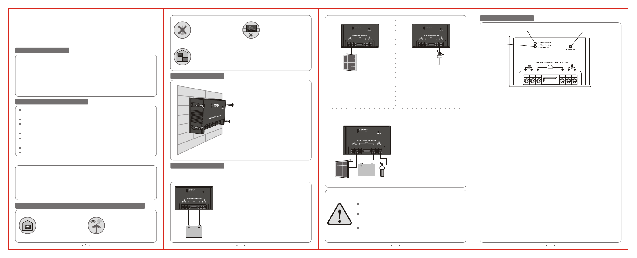
Mounting & Installation
4 screws are provided for mounting
purposes.
Please ensure both cooling vents
on either side of the controller are
free from obstruction to ensure
sufficient air flow.
Connection Sequence
*Warning:The following connection sequence must be followed at all
times to avoid possible damage and personal injury!
1 Battery Connection
The battery must be connected first
using the clearly marked connections
on the controller.
Note the recommended distance
30~100cm
Battery
between the battery and the controller
should be between 30cm and 100cm.
The controller has reverse polarity
connection, just change the polarity
if the battery is incorrectly connected.
2 3 4
Solar Panel
2 Solar Module Connection
Connect the wires to the
controller first, then connect
the panel.
4 Complete Wire Connection Diagram
Recommended System
Wire Sizes(including wires
between the controller and
panel, battery, load):
Solar Panel
Battery
Warning - Important Safety Instructions when
connecting the panel.
Put the positive and negative of the wire close to reduce
the electromagnetic interference.
Do not connect the solar module while it is exposed to
daylight. This may generate voltage instantly, causing
system damage and/or personal injury.
Ensure the solar module is rated at the correct voltage
to charge the battery you are connecting, failure to do
so may cause permanent harm to the battery.
Load
SC24-10: at least 6.0 mm²
Load
3 Load (Device) Connection
Connect load (Device) first and
then controller to avoid any
damage and/or malfunctions.
LED Display Function
Amber LED
Green LED
Red LED
LED Explanation
Amber LED:
On (Solid):The controller is connected correctly/Battery fully charged.
On (Flashing):Controller is charging.
Red LED:
On (Solid):The battery is fully charged.
Green LED:
On (Solid):Load output is OK.
Off:Battery voltage is low.
LED Sequence
Phase 1 - Amber LED Flashing, no other LEDS are lit
Battery is being charged and voltage is below 12.4V for 12V systems
and 24.8V for 24V systems.
Note: When the voltage is under 11.1V (12V system) or 22.2V (24V
system), the battery will stop powering the load.
Phase 2 - Amber LED is flashing and the Green LED is lit
Battery has reached 12.4V or 24.8V and the controller continues to
charge.
Phase 3 - Amber LED is flashing, Green LED is lit
Battery has reached maximum charge around 14.4V or 28.8Vand the
controller remains charging with a very small trickle charge.
Phase 4 - Yellow LED, Red LED and Green LED are all lit (No flashing)
Battery has reached 13.8V, no charging is taking place.
Phase 5 - Yellow LED starts flashing, Red LED turns off and Green LED
stays on
Battery has reached 13.2V, and the controller has started charging again.
If voltage drops below 12.4V due to load the Green LED will turn off.
Page 2
Trouble-shooting Guide
Troubles
Can not
power the
load
Battery
power of
short
duration
Battery can
not be
charged
Battery be
fully charged
quickly
Controller
Not
Operating
Display
Green LED off
Green LED off
Amber LED
not flash
Red and
LED
Amber
on
Green LED off
LED
Amber
and Red LED
flash
Low battery
Load exceeds
controller rating
or short circuit
exists
Battery volts high
12V system>15.5V
24V system>31V
Battery connection
or fuse damaged,
battery internal
resistance high
Battery capacity is
low
Solar module
polarity reversed,
solar module or its
wiring damaged,
fuse open circuit
Battery I.R. high,
capacity low.
Connecting wire
too thin and too
long
Load current over
the rated value
Or
Load short circuit
5
Corrective MeasuresPossible Cause/s
Battery likely requires
charging
Turn off all the load,
trouble shooting,
change new fuse
Check if battery
open-circuit, if not,
the battery maybe
damaged
Check the battery
connection, check
fuse and battery
condition
Battery likely requires
replacement
Check the module
polarity and
connection
Battery likely requires
replacement and
new, shorter/thicker
connecting wires
should be installed
If it is not cause by
over-load or
short-circuit, please:
Option1: Press the
reset button in
controller back.
Option2: Reconnect
the controller after a
few seconds
Suggestions for Safe and Secure Use
Failure to follow these complete instructions and the suggestions
below may cause system damage and/or personal injury.
This controller is only designed for 12V/24V solar charging.
The built-in electronic circuit protector keeps the controller away from
overcharging, overflowing, overloading and short-circuit.
Sealed, maintenance free VLRA Batteries are highly recommended
Do not connect any voltage stabilizer or charger to solar panel's
terminals this can cause damage to the controller.
The controller will heat up during use, place in a well-ventilated
location and avoid contact with the controller surface.
Keep the ventilation holes on the controller free of dust and debris.
Avoid battery short circuit at all times.
The battery may produce flammable gases, please keep away from
spark or open flame, ensure the battery is kept in a well-ventilated
location.
Fully charge the battery at least once a month.
Do not contact or short circuit the terminals or wires.
Please use insulated tools during operation, keep both hands dry and
do not stand on the wet ground.
Please keep the children away from the battery and the controller.
Please follow the security recommendations from the battery
manufacturer. Contact the distributor or the installation personnel if
there is any doubt.
It is recommended that a certified electrician install and connect the
system.
General Disclaimer
In no event shall the manufacturer liable for any damage or
personal injury caused by non-compliance to the operating
instructions and safety suggestions in this brochure. The
manufacturer will not bear any responsibility for misuse, damage,
injury, incorrect installation and/or system design as such.
6 7
1515
1010
12/24
88
24V system: 27.6±0.4
12V system: 13.8±0.2
24V system: 28.2~29
24V system: 24.4~25.2
12V system: 12.2~12.6
24V system: 21.6~22.8
12V system: 10.8~11.2
12V system: 14.1~14.5
55
≤8
15 15
≤0.4
SLC-B Smart Solar Charge Controller
5000
-3mV/cell*K
-20°C~50°C
Models
SLC-1205B/08B/10B/15B
(For 12V System Only)
SLC-2405B/08B/10B/15B
(12V/24V Automatic Identification)
10 10
12
13.8±0.2
10.8~11.2
14.1~14.5
12.2~12.6
8 8
≤0.4
≤0.3 ≤0.3
User Manual
&
5 5
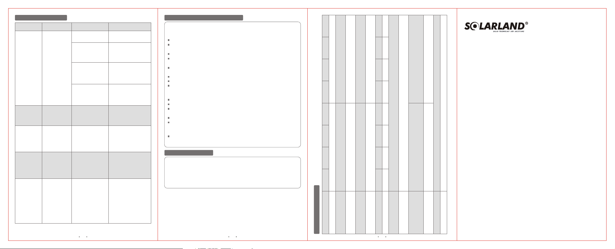
SLC-1205B SLC-1208B SLC-1210B SLC-1215B SLC-2405B SLC-2408B SLC-2410B SLC-2415B
Technical Parameters
Model
Rated voltage (V)
Float voltage (V)
Over-charging
Load disconnect
protection voltage (V)
Max .solar current(A)
Max. load current (A)
Load reconnect
voltage (V)
voltage (V)
Typical power
Temperature
Voltage drop between
compensation factor
consumption (mA)
solar power and
Ambient temp. range(°C)
Voltage drop between
Max. altitude(m)
battery and load (V)
battery (V)
Product Specifications
 Loading...