


PRN800 MX Printer MZX Fire alarm system
© Tyco Fire & Security GmbH, Victor von Bruns-Strasse 21, 8212 Neuhausen
am Rheinfall, Switzerland
www.zettlerfire.com
120.415.535_17A-03-PRN, doc. version 3, 22. March 2017
Subject to change without notice.
Paper roll replacement
1 Undo the two Supadrive™ screws and
remove the printer mechanism front
cover.
2 Pull out the paper drive spindle.
3 Pull out the paper roll retaining bar and
slide off the old paper roll.
4 Put the new paper roll onto the paper roll
retaining bar with the paper feeding from
the rear.
5 Press the paper roll retaining bar back into
its grooves.
6 Feed the paper over the paper drive spin-
dle and press the spindle back into its
retaining grooves.
7 Feed the paper through the printer mecha-
nism front cover slot and refit the retaining
screws.
Ordering information
Fig. 3: Paper change
1 –Paper drive spindle
2 –Paper roll retaining bar
1
2
Item Order Code
Spare paper roll (pk of 5) 557.301.014
Fig. 4: Order codes
MZX Fire alarm system PRN800 MX Printer
Fixing Instructions Doc. version 3 1/4
PRN800 MX Printer
Part No. 557.202.024
The PRN800 is fitted to the front cover of the
MX /T2000 battery housing/MX2 Expansion box housing and is powered from the
panel PSU830 Power Supply via an FB800
fuse board. The use of a thermal printer mechanism ensures high reliability, only the paper
roll requires replacement periodically.
Installation instructions
The installation instructions are as follows:
1 Open the battery/expansion housing
and loosen or remove the relevant
blanking strips holding the top blanking plate onto the front door.
Fig. 1: PRN800 MX printer kit
1 –Paper feed button
1
NOTICE
The PRN800 Printer kit is
designed for use within the MX/
T2000 battery housing and MX2
Expansion box housing.
CAUTION
The printer assembly must be
powered via a FB800 fuse board
using a 0.5 A time delay fuse.
A free cable entry hole is required
in both the controller and battery/
expansion housings.
Any cable runs must be protected
by conduit or trunking.
2/4 Fixing Instructions Doc. version 3
PRN800 MX Printer MZX Fire alarm system
2 Remove the blanking plate and fit the
printer assembly.
3 Re-tighten blanking strips to secure
printer assembly.
4 Locate a spare cable entry gland into
the housing. If none is available, then
a knockout must be removed.
5 To remove a knockout, remove any
fouling PCBs (or wiring) to prevent
swarf or metal filings damaging them.
6 Holes for the cable entry gland must
be drilled in the T2000/T2000 battery
housing gland plates.
7 Connect data lead to printer assem-
bly. Data cable should be connected
to COM1 on FIM inside the MX/
T2000/MX2 housing.
8 Locate a spare 24V fused output on
the FB800 fuseboard. Remove 0.5A
fuse. Connect red and black wires of
power cable assembly to +24V and 0V
respectively.
– Connect power lead to 24V dc fused
supply input TB1 (See Item 6 in
Fig. 2) of printer assembly.
Note: At TB1, connect +24V to the
pin VM and -0V to the pin 0V respectively.
– Power and data cables may be run
together if required through an
appropriate conduit and should be
separated from other field wiring of
the MX/T2000 panel.
9 Fit the paper roll to printer mecha-
nism, as described in Paper Roll
Replacement.
10 Replace the 0.5A fuse taken from the
FB800 fuseboard.
11 Check that the jumper links are cor-
rectly fitted on the Printed Circuit
Board.
– Configure the jumper links as indi-
cated in Fig. 2.
12 Configure the printer using MZX CON-
SYS as follows:
– In the Printers dialog box:
Printer Address - COM1, tick Enabled
Printer Name - PRINTER
Paper Width -Narrow (40)
Printer Type - Standard Printer
Quiescent Logging - tick if required
Default Printer - tick
– In the Communication Ports dialog
box:
Set the Baud Rate to 9600
13 Save the printer configuration, then
download the new configuration.
14 The PRN800 is now installed.
NOTICE
All necessary precautions
must be taken to protect
wiring and PCBs.
MZX Fire alarm system PRN800 MX Printer
Fixing Instructions Doc. version 3 3/4
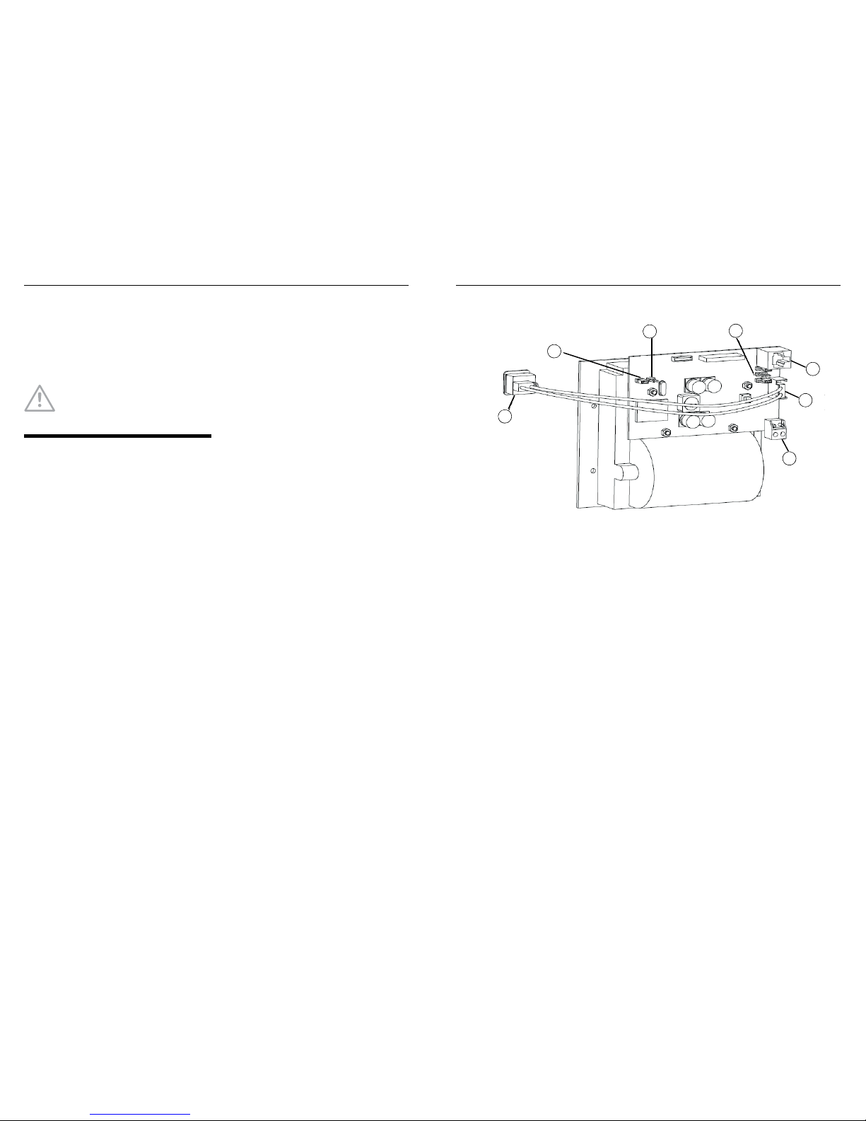
Fig. 2: Printer configuration - Jumper setting (1-3) and wiring connections (4-7)
1 –LK6 ON
2 –LK5 OFF
3 –LK1 RIGHT, LK2 OFF, LK4 RIGHT
4 –Printer connector for RS232
5 –Cable to paper feed button
6 –Printer hea der connector for power supply cable
7 –Connection t o paper feed button
1
2
3
4
5
6
7

PRN800 MX-Drucker MZX-Brandmeldeanlage
© Tyco Fire & Security GmbH, Victor von Bruns-Strasse 21, 8212 Neuhausen
am Rheinfall, Schweiz
www.zettlerfire.com
120.415.535_17A-03-PRN-DEU, Dok.-Version 3, 6. April 2017
Änderungen vorbehalten.
Wechseln der Papierrolle
1 Lösen Sie die beiden Supadrive™-Schrau-
ben und nehmen Sie die vordere Abdec-
kung des Druckerwerks ab.
2 Ziehen Sie die Papiervorschubrolle her-
aus.
3 Ziehen Sie den Haltestift der Papierrolle
heraus und schieben Sie die alte Papier-
rolle herunter.
4 Setzen Sie die neue Papierrolle auf den
Haltestift und führen Sie dabei das Ende
des Papierstreifens von hinten nach vorne.
5 Drücken Sie den Haltestift wieder in die
Kerben.
6 Führen Sie das Papier über die Papiervor-
schubrolle und drücken Sie die Rolle wie-
der in die Haltekerben.
7 Fädeln Sie das Papier durch den Schlitz in
der vorderen Abdeckung des Druckerwerks und bringen Sie die Befestigungsschrauben wieder an.
Bestellinformationen
Abb. 3: Papierwechsel
1 –Papiervorschubrolle
2 –Haltestift für Papierrolle
1
2
Komponente Bestellnum-
mer
Ersatzpapierrolle (5er
Pack):
557.301.014
Abb. 4: Bestellnummern
MZX-Brandmeldeanlage PRN800 MX-Drucker
Montagehinweis Dok.-Version 3 1/4
PRN800 MX-Drucker
Teilenr. 557.202.024
Der PRN800 wird an der Vordertür des MZX/
T2000-Batteriegehäuses bzw. MX2-Universalgehäuses montiert und durch die Energieversorgung PSU830 über die Sicherungsplatte FB800 mit Strom gespeist. Durch das
Thermo-Druckverfahren wird eine hohe
Zuverlässigkeit des Druckers erreicht. Lediglich die Papierrolle muss regelmäßig gewechselt werden.
Abb. 1: PRN800 MX-Druckerkit
1 –Papierzufuhrtaste
1
HINWEIS
Das PRN800-Druckerkit ist für die
Verwendung mit dem MZX/
T2000-Batteriegehäuse und
dem MX2-Universalgehäuse
vorgesehen.
VORSICHT
Die Stromversorgung des
Druckermoduls muss über eine
FB800-Sicherungsplatte unter
Verwendung einer trägen 0,5-ASicherung erfolgen.
Sowohl im Zentralen- als auch im
Batterie-/Erweiterungsgehäuse
muss eine freie
Kabeleinführungsöffnung
vorhanden sein.
Alle Kabelwege müssen durch
geeignete Maßnahmen
mechanisch geschützt werden.

2/4 Montagehinweis Dok.-Version 3
PRN800 MX-Drucker MZX-Brandmeldeanlage
Installations- und Montageanleitung
Gehen Sie zur Installation wie folgt vor:
1 Öffnen Sie das Batterie-/Erweite-
rungsgehäuse und lösen oder entfer-
nen Sie die entsprechenden Leisten,
mit denen die obere Blindplatte an der
Vordertür befestigt ist.
2 Nehmen Sie die Blindplatte ab und
setzen Sie das Druckermodul ein.
3 Bringen Sie die Blindleisten wieder
fest an, um das Druckermodul zu
sichern.
4 Suchen Sie nach einer freien Kabel-
verschraubung im Gehäuse. Wenn
keine vorhanden ist, muss eine Öff-
nung gebohrt werden.
5 Entfernen Sie zum Bohren der Öff-
nung alle angrenzenden Leiterplatten
(oder Kabel), sodass diese nicht durch
Bohrspäne oder Metallstaub beschä-
digt werden.
6 Die Öffnung für die Kabelverschrau-
bung muss in die dafür vorgesehene
Platte des MZX/T2000-Batteriegehäu-
ses gebohrt werden.
7 Verbinden Sie das Datenkabel mit
dem Druckermodul. Das Datenkabel
muss an COM1 auf der FIM-Hauptpla-
tine im Inneren des MZX/T2000/MX2Gehäuses angeschlossen werden.
8 Suchen Sie einen freien gesicherten
24-V-Ausgang auf der FB800-Sicherungsplatte. Bauen Sie die 0,5-ASicherung aus. Schließen Sie die
roten und schwarzen Leitungen des
Kabelsatzes an +24 V bzw. 0 V an.
– Schließen Sie die Leitung für die
Spannungsversorgung an den gesicherten 24-VDC-Eingang TB1 (siehe
Komponente 6 in Abb. 2) des Druckermoduls an.
Hinweis: Verbinden Sie an TB1
+24 V mit Pin VM und -0 V mit
Pin 0V.
– Das Netz- und Datenkabel können
bei Bedarf zusammen in einem
geeigneten Kabelkanal verlegt werden und sollten von anderen Feldverdrahtungen der MZX/T2000-Zentrale
getrennt werden.
9 Setzen Sie die Papierrolle in das Druc-
kerwerk, wie unter „Wechseln der
Papierrolle“ beschrieben.
10 Setzen Sie die aus der FB800-Siche-
rungsplatte ausgebaute 0,5-A-Sicherung wieder ein.
11 Überprüfen Sie, dass die Steckbrüc-
ken richtig auf der Leiterplatte eingesetzt sind.
– Konfigurieren Sie die Steckbrücken
wie in Abb. 2 dargestellt.
12 Konfigurieren Sie den Drucker über
MZX CONSYS wie folgt:
– Im Dialogfeld „Drucker“:
Wählen Sie unter „Druckeradresse
– COM1“ die Option „Aktiviert“
aus
Druckername – DRUCKER
HINWEIS
Es müssen alle notwendigen
Maßnahmen zum Schutz der
Kabel und Leiterplatten
getroffen werden.
MZX-Brandmeldeanlage PRN800 MX-Drucker
Montagehinweis Dok.-Version 3 3/4
Papierbreite – Narrow (40)
Druckertyp – Standarddrucker
Protokollierung im Ruhezustand –
bei Bedarf aktivieren
Standard-Drucker – aktivieren
– Im Dialogfeld „Kommunikations-
ports“:
Stellen Sie die Baudrate auf 9600
ein
13 Speichern Sie die Druckerkonfigura-
tion und laden Sie anschließend die
neue Konfiguration herunter.
14 Der PRN800 ist nun installiert.
Abb. 2: Druckerkonfiguration – Steckbrückeneinstellung (1-3) und Verdrahtungsverbindungen (4-7)
1 –LK6 ON
2 –LK5 OFF
3 –LK1 RECHTS, LK2 OFF, LK4 RECHTS
4 –Druckerverbindung für RS232
5 –Kabel zur Papierzufuhrtaste
6 –Verbindung der Druckersteckbrücke für das Stromversorgungskabel
7 –Anschluss zur Papierzufuhrtaste
1
2
3
4
5
6
7
 Loading...