

Tyco Healthcare AG 6325 User manual

Operation
&
Service
MODEL
Manual
6325
COMPRESSION
#YCO
KENDALL
SYSTEM
/
Healthcare
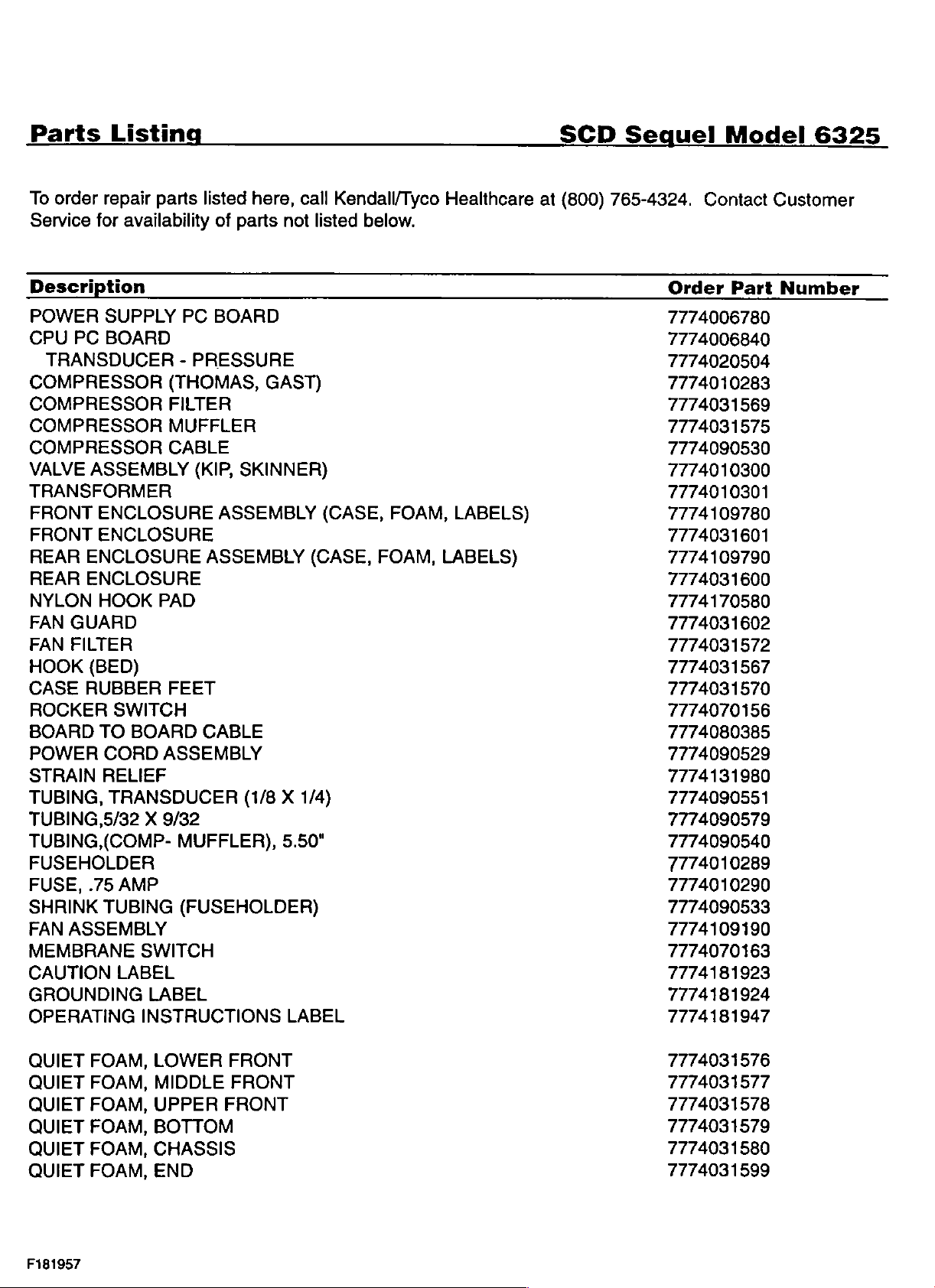
Parts
To
order
Service
Description
POWER
CPU
TRANSDUCER
COMPRESSOR
COMPRESSOR
COMPRESSOR
COMPRESSOR
VALVE
Listing
repair
for
availability
SUPPLY
PC
BOARD
ASSEMBLY
parts
PC
-
(THOMAS,
FILTER
MUFFLER
CABLE
TRANSFORMER
FRONT
FRONT
REAR
REAR
NYLON
FAN
FAN
HOOK
CASE
ROCKER
BOARD
POWER
STRAIN
TUBING,
ENCLOSURE
ENCLOSURE
ENCLOSURE
ENCLOSURE
HOOK
GUARD
FILTER
(BED)
RUBBER
SWITCH
TO
BOARD
CORD
RELIEF
TRANSDUCER
PAD
FEET
ASSEMBLY
TUBING,5/32 X 9/32
TUBING,(COMP-
MUFFLER),
FUSEHOLDER
FUSE,
SHRINK
FAN
MEMBRANE
CAUTION
GROUNDING
OPERATING
.75
AMP
TUBING
ASSEMBLY
LABEL
(FUSEHOLDER)
SWITCH
LABEL
INSTRUCTIONS
listed
of
here,
parts
BOARD
PRESSURE
(KIP,
SKINNER)
ASSEMBLY
ASSEMBLY
CABLE
(1/8 X 1/4)
call
not
GAST)
5.50"
LABEL
Kendall/Tyco
listed
(CASE,
below.
(CASE,
FOAM,
FOAM,
Healthcare
LABELS)
LABELS)
SCD
at
(800)
Sequel
765-4324.
Order
7774006780
7774006840
7774020504
7774010283
7774031569
7774031575
7774090530
7774010300
7774010301
7774109780
7774031601
7774109790
7774031600
7774170580
7774031602
7774031572
7774031567
7774031570
7774070156
7774080385
7774090529
7774131980
7774090551
7774090579
7774090540
7774010289
7774010290
7774090533
7774109190
7774070163
7774181923
7774181924
7774181947
Model
Contact
Part
6325
Customer
Number
QUIET FOAM,
QUIET
QUIET
QUIET
QUIET
QUIET
F181957
FOAM,
FOAM,
FOAM,
FOAM,
FOAM,
LOWER
MIDDLE
FRONT
FRONT
UPPER FRONT
BOTTOM
CHASSIS
END
7774031576
7774031577
7774031578
7774031579
7774031580
7774031599
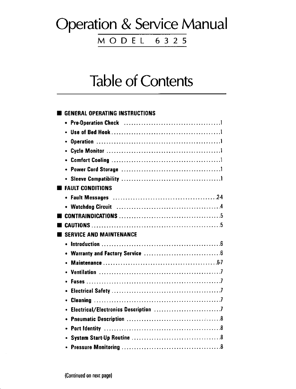
Operation
&
Service
Manual
M
GENERAL
e
Pre-Operation
*
Use
+
Operation
e
Cycle
©
Comfort
+
Power
+
Sleeve
M
FAULT
MODEL
Table
OPERATING
Check
of
Bed
Hook............................................
....................................,..,.,,,,,4.
Monitor
Cord
Compatibility
CONDITIONS
..........................,,..................
Cooling
Storage
6325
of
Contents
INSTRUCTIONS
.......................................
...................................,........
........................................
........................................
1
1
1
1
1
1
1
e
Fault
Messages
ㆍ
Watchdog
M
CONTRAINDICATIONS
M
CAUTIONS
E
SERVICE
slntroduction.............................
e
Warranty
+
Maintenance
e
Ventilation
efFuses.................................
+
Electrical
e
Cleaning
*
Electrical/Electronics
e
Pneumatic
e
Portidentity
»
System
+
Pressure
Circuit
.............................,.,....,..........,.,.
AND
and
Safety
.................................,...............
Start-Up
Monitoring
.................................,..,..,..
.........................................1
...........................,.............
MAINTENANCE
Factory
.........................................,....
.................................................
Description
............................................
Service
............................................
Description
...............................:
Routine
........................................
...............................
...........................
....................................
eee
eee
Fer
24
4
5
5
6
6
6-7
7
7
7
7
7
8
8
8
8
(Continued
on
next
page}
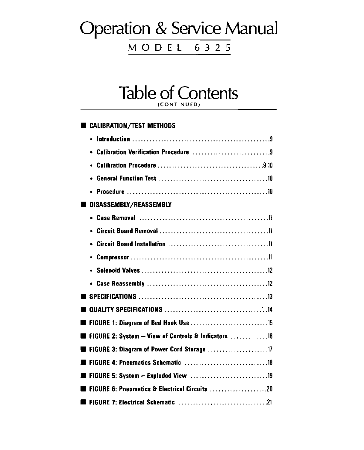
Operation
&
Service
Manual
MODEL
Table
M
CALIBRATION/TEST
.latroduction..............................
*
Calibration
.CalibrationProcedure.....................................
e
General
+
Procedure
Ш
DISASSEMBLY/REASSEMBLY
»eCaseRemoval
Verification
Function
.....................,..........................
.............................................
of
(CONTINUED)
METHODS
Procedure
Test
......................................
6325
Contents
1...
eee
...........................
9
9
9-10
10
10
1
eCircuitBoardRemoval......................................
+
Circuit
+
Compressor..........................................,.....
+
Solenoid
«
Case
画
SPEEIFICATIONS
HE
QUALITY
E
FIGURE
@
FIGURE
@
FIGURE
M
FIGURE
E
FIGURE
Ш
FIGURE
BB
FIGURE
Board
Reassembly
SPECIFICATIONS
1:
2:
3:
4:
5:
6:
7:
Installation
Valves
...................,...,.,.......,..........
..........................................
...................................
..................................
Diagram
System — View
Diagram
Pneumatics
System — Exploded
of
Bed
of
of
Power
Schematic
Hook
Controls & Indicators
Cord
View
Pneumatics & Electrical
Electrical
Schematic
ων
νε
νο
ων κκ
νε
κκ
Use
...........................
.............
Storage
.............................
Circuits
...............................
.....................
...........................
....................
1
1
1
12
12
18
、.4
15
16
7
18
19
20
2
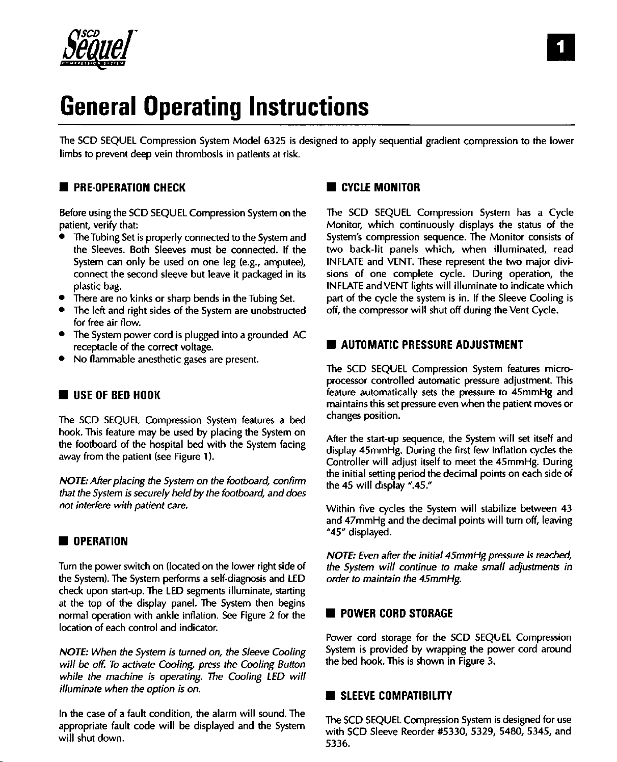
General
The
SCD
SEQUEL
limbs
to
prevent
M
PRE-OPERATION
Before
using
the
patient,
©
©
©
©
©
Ш
The
hook.
the
away
NOTE:
that
not
E
Turn
the
check
at
normal
location
NOTE:
will
while
illuminate
In
appropriate
will
verify
The
Tubing
the
Sleeves.
System
connect
plastic
There
The
for
The
receptacle
No
USE
footboard
interfere
can
bag.
are
left
free
air
System
flammable
OF
SCD
SEQUEL
This
feature
from
the
After
the
System
the
and
BED
placing
OPERATION
the
power
System).
the
upon
top
The
start-up.
of
operation
of
each
When
be
off.
To
the
machine
when
the
case
of a fault
fault
shut
down.
Operating
Compression
deep
SCD
that:
Set
is
Both
only
second
no
kinks
right
flow.
power
of
the
anesthetic
HOOK
may
of
the
patient
is
securely
with
patient
switch
System
the
display
with
control
the
System
activate
the
code
vein
thrombosis
System
Model
in
patients
CHECK
SEQUEL
properly
Sleeves
be
or
sides
cord
correct
Compression
hospital
(see
the
on
The
ankle
is
option
condition,
Compression
connected
must
used
on
sleeve
but
sharp
bends
of
the
is
plugged
voltage.
gases
be
used
by
bed
Figure
System
held
care.
on
by
(located
performs a self-diagnosis
LED
segments
panel.
The
inflation.
and
indicator.
is
turned
Cooling,
press
operating.
is
on.
the
will
be
displayed
to
the
be
connected.
one
leg
(e.g.,
leave
it
packaged
in
the
System
on
are
into a grounded
are
present.
System
placing
with
1).
the
the
on, the
The
features a bed
the
footboard,
footboard,
the
lower
illuminate,
System
See
Figure 2 for
Sleeve
the
Cooling
Cooling
alarm
will
and
Instructions
6325
is
at
risk.
System
Tubing
the
System
on
the
System
unobstructed
right
then
and
If
the
amputee),
in
its
Set.
AC
System
on
facing
confirm
and
does
side
of
and
LED
starting
begins
the
Cooling
Button
LED
will
sound.
The
the
System
designed
to
apply
M
CYCLE
The
SCD
Monitor,
System’s
two
INFLATE
sions
INFLATE
part
off,
which
compression
back-lit
and
of
one
and
of
the
the
compressor
AUTOMATIC
The
SCD
SEQUEL
processor
feature
maintains
changes
After
display
Controller
the
the
Within
and
“45”
NOTE:
the
order
MW
Power
System
the
E
The
with
controlled
automatically
this
position.
the
start-up
45mmHg.
initial
setting
45
will
five
47mmHg
displayed.
Even
System
to
maintain
POWER
cord
is
provided
bed
hook.
SLEEVE
SCD
SEQUEL
SCD
Sleeve
5336.
sequential
MONITOR
SEQUEL
panels
VENT.
VENT
cycle
set
will
display
cycles
and
after
will
CORD
storage
This
COMPATIBILITY
gradient
Compression
continuously
sequence.
which,
These
represent
complete
the
lights
will
system
will
shut
cycle.
is
PRESSURE
Compression
automatic
sets
the
pressure
sequence,
During
adjust
period
the
the
continue
the
itself
the
“.45.”
the
System
decimal
initial
45mmHg.
even
the
the
to
decimal
45mmHg
to
STORAGE
for
the
by
wrapping
is
shown
Compression
Reorder
in
#5330,
compression
System
displays
The
Monitor
when
illuminate
in.
off
the
During
If
the
during
illuminated,
the
ADJUSTMENT
System
pressure
pressure
when
the
System
first
few
inflation
meet
the
45mmHg.
points
will
stabilize
points
will
pressure
make
small
SCD
SEQUEL
the
power
Figure
3.
System
is
5329,
to
the
has a Cycle
the
status
of
consists
two
major
operation,
to
indicate
Sleeve
Vent
features
adjustment.
to
45mmHg
patient
will
on
turn
adjustments
designed
5480,
which
Cooling
Cycle.
micro-
moves
set
itself
cycles
During
each
side
between
off,
leaving
is
reached,
Compression
cord
around
for
5345,
lower
the
of
read
divi-
the
is
This
and
or
and
the
of
43
in
use
and
Model
6325
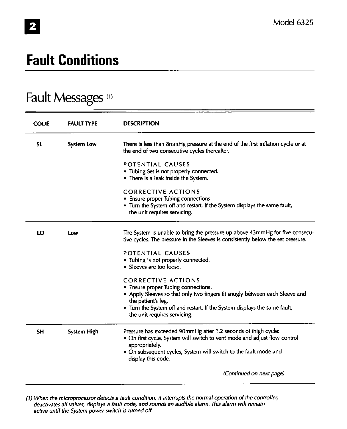
Fault
Fault
CODE
SL
Conditions
Messages
FAULT
System
TYPE
Low
”
DESCRIPTION
There
is
less
the
end
of
two
POTENTIAL
*
Tubing
*
There
CORRECTIVE
©
Ensure
*
Turn
the
Set
is a leak
proper
the
System
unit
requires
than
8mmHg
consecutive
CAUSES
is
not
properly
inside
ACTIONS
Tubing
off
and
servicing.
pressure
cycles
the
System.
connections.
restart.
at
thereafter.
connected.
If
the
the
end
System
of
the
first
displays
inflation
the
same
cycle
fault,
or
at
Lo
SH
(1)
When
deactivates
active
Low
System
the
microprocessor
all
valves,
until
the
System
The
tive
POTENTIAL
*
*
CORRECTIVE
*
*
High
detects a fault
displays a fault
power
switch
Pressure
*
*
code,
is
System
cycles.
is
unable
The
pressure
CAUSES
Tubing
Sleeves
Ensure
Apply
the
Turn
the
On
is
not
are too
proper
Sleeves
patients
the
unit
first
leg.
System
requires
has
exceeded
cycle,
properly
loose.
ACTIONS
Tubing
so
off
servicing.
System
appropriately.
On
subsequent
display
turned
this
condition,
and
sounds
off.
cycles,
code.
it
interrupts
an
to
bring
in
the
connected.
connections.
that
only
two
and
restart.
90mmHg
will
switch
Systern
the
audible
the
pressure
Sleeves
fingers
If
the
after
to
will
normal
alarm.
up
above
is
consistently
fit
snugly
System
1.2
seconds
vent
mode
switch
to
(Continued
operation
This
alarm
43mmHg
below
between
displays
the
of the
will
the
of
thigh
and
adjust
fault
mode
on
next
controller,
remain
for
five
the
set
each
Sleeve
same
fault,
cycle:
flow
control
and
page)
consecu-
pressure.
and
Segue
Fault
CODE
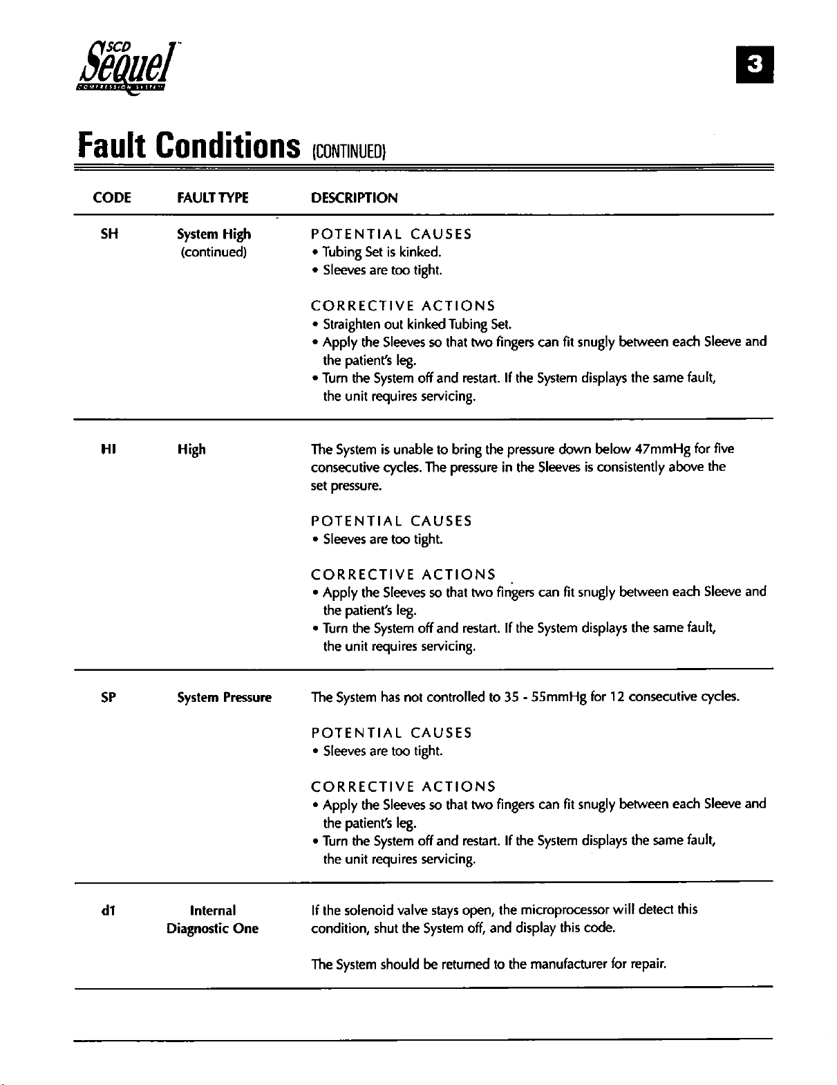
SH
HI
Conditions
FAULT
TYPE
System
High
High
(continued)
comwe
DESCRIPTION
POTENTIAL
©
Tubing
©
Sleeves
CORRECTIVE
*
Straighten
+
Apply
the
e
Tum
the
The
consecutive
set
POTENTIAL
*
Sleeves
Set
are
the
patients
the
System
unit
requires
System
is
pressure.
are
CAUSES
is
kinked.
too
tight.
ACTIONS
out
kinked
Sleeves
so
leg.
off
servicing.
unable
cycles.
The
CAUSES
too
tight.
Tubing
that
two
and
restart.
to
bring
pressure
Set.
fingers
If
the
the
pressure
in
the
can
fit
snugly
System
down
Sleeves
between
displays
is
the
below
47mmH
consistently
each
same
above
Sleeve
fault,
for
five
the
and
CORRECTIVE
+
Apply
the
the
patients
*
Turn
the
System
the
unit
reguires
The
SP
System
Pressure
System
POTENTIAL
+
Sleeves
are
CORRECTIVE
+
Apply
the
the
patients
e
Turn
the
System
the
unit
reguires
If
the
di
internal
Diagnostic
One
solenoid
condition,
The
shut
System
ACTIONS
Sleeves
leg.
off
servicing.
has
not
CAUSES
too
tight.
ACTIONS
Sleeves
leg.
off
servicing.
valve
the
should
so
that
two
and
restart.
controlled
so
that
and
stays
System
be
returned
to
two
restart.
open,
off,
and
|
fingers
If
the
can
System
35 - 55mmHg
fingers
to
can
If
the
System
the
microprocessor
display
the
manufacturer
fit
snugly
displays
fit
snugly
displays
this
code.
between
the
for
12
consecutive
between
the
will
for
repair.
each
same
each
same
detect
Sleeve
fault,
cycles.
Sleeve
fault,
this
and
and
Model
6325
Fault
CODE
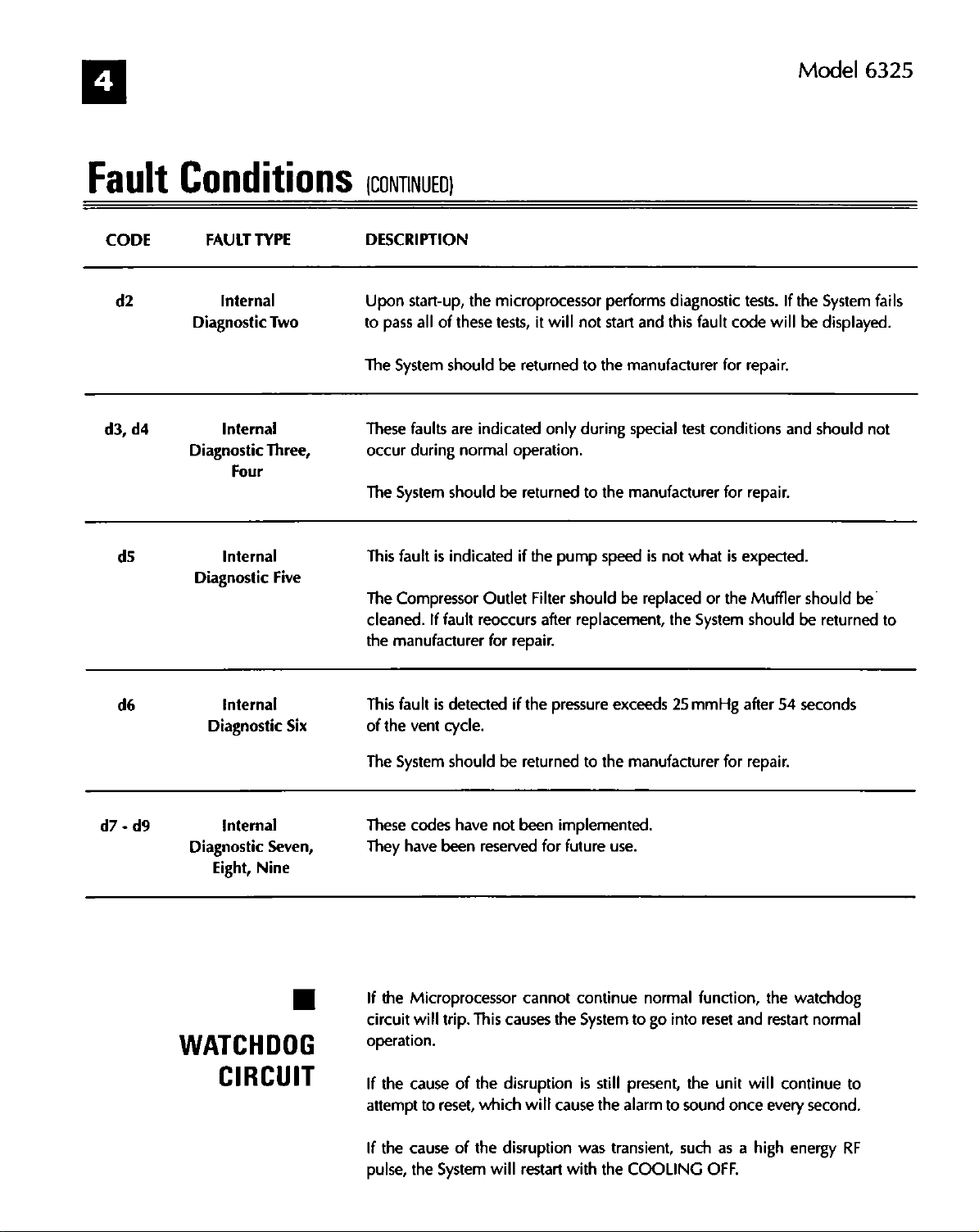
d2
d3,
d4
ds
Conditions
FAULT
TYPE
Internal
Diagnostic
Diagnostic
Diagnostic
Two
Internal
Three,
Four
Internal
Five
commun
DESCRIPTION
Upon
start-up,
to
pass
all
of
these
The
System
These
occur
The
System
This
The
Compressor
cleaned.
the
manufacturer
faults
during
fault
is
If
should
are
normal
should
indicated
fault
the
microprocessor
tests,
it
will
be
returned
indicated
Outlet
reoccurs
for
only
operation.
be
returned
if
the
Filter
after
repair.
performs
not
start
to
the
manufacturer
during
pump
should
replacement,
special
to
the
manufacturer
speed
be
diagnostic
and
this
test
is
not
what
replaced
the
tests.
fault
code
for
repair.
conditions
for
repair.
is
expected.
or
the
Muffler
System
should
If
the
will
be
and
be
System
displayed.
should
should
not
be
returned
fails
to
d7 - d9
de
internal
Diagnostic
Internal
Diagnostic
Eight,
Six
Seven,
Nine
WATCHDOG
CIRCUIT
This
fault
is
of
the
vent
cycle.
The
System
These codes
They
have
been
If
the
Microprocessor
circuit
will
trip.
operation.
If
the
cause
attempt
If
pulse,
the
to
reset,
cause
the
System
detected
should
have
be
not
reserved
This
causes
of
the
disruption
which
of
the
disruption
will
if
the
pressure
returned
been
implemented.
for
future
cannot
the
will
cause
restart
exceeds
to
the
use.
continue
System
is
still
the
was
transient,
with
the
25
mmHg
manufacturer
normal
to
present,
alarm
COOLING
go
to
function,
into
reset
the
sound
such
OFF.
after
for
repair.
the
and
restart
unit
will
once
every
as a high
54
seconds
watchdog
normal
continue
second.
energy
to
RF
 Loading...