

TYCO Healthcare 7325 User manual
©
Operation
&
Service
MODEL
Manual
SCD
7325
response“
compression
#YCO
(Healthcare
KENDALL
system

Operation
&
Service
Manual
MODEL
Table
BI
INDICATIONS
Æ
CONTRAINDICATIONS
E
CAUTIONS
@
GENERAL
e
Pre-Operation
+
Use
of
+
Operation
+
Automatic
*
Vascular
.................
..............................................
OPERATING
Bed
Hook .......................................
.............................................
Pressure
Refill
of
....................................
INSTRUCTIONS
Check
Detection
..................................
Adjustment
7325
Contents
ρω ν νο
νεο
νεο
νεο
ών
ον
Ί
1
1
2
2
2
.........................
...............................
2
2
+
Cycle
Monitor
e
Comfort
e
Power
»
Sleeve
Ш
FAULF
¢
Watchdog
@
SERVICE
+
Introduction
+
Warranty
ο
.Ventilation............................................
*Fuseş.....................................
'ElectricalSafety
+
Cleaning.
»
Electrical/Electronics
+
Pneumatic
。
PortldentiW
Cooling
Cord
Compatibility
CONDITIONS
AND
.........................................
.......................................
Storage
Circuit
MAINTENANCE
....................
and
Factory
μμ
..............................................
Description
....................................
...................................
......................................
......................................
ит
иене
Service
ϱϱ”-.
......................................
Description
.................................
...........
.......................
P
11
ω
ken
νε
ων 9
3
3
3
3
4
6
7
7
7
8
8
8
8
8
9
+
System
e
Pressure
Start-Up
Monitoring
Routine
................................
...................................
9
9
Operation
&
Service
Manual
MODEL
Table
BE
CALIBRATION/TEST
+
Introduction
*
Ankle
ㆍ
Ankle
«
Calf
¢
Calf
+
E
DISASSEMBLY/REASSEMBLY
Calibration
Calibration
Calibration
Calibration
General
Function
METHODS
...................................,...,..
Verification
Procedure
Verification
Procedure
Test
7325
of
Contents
(CONTINUED)
10
Procedure
...........................
Procedure
.............................
.................................
................
..................
10
11
11
12
13
-_
Front
Cabinet
+
Circuit
+
Circuit
»eCompressor..........................................
e
Compressor
e
Valves
»eUnitReassembiy......................................
Ш
SPECIFICATIONS..
画
QUALITYSPECIFICGATIONS
E
FIGURE
М
FIGURE
MH
FIGURE
El
FIGURE
M
FIGURE
Board
Board
1:
2:
3:
4:
5:
Removal
Removal
Installation
Outlet
...............................,.......,.......
.....................................,.
Diagram
System — View
Diagram
Pneumatics
System — Exploded
of
of
.................................
.................................
..............................
Filter
...............................
.
Bed
Hook
of
Controls & Indicators
Power
Schematic
Cord
View................
Use
.......................
Storage.
.........................
.................
이
이이
..........
Vecio
15
15
15
15
16
16
16
17
18
19
20
21
22
23
Mi
FIGURE
M
FIGURE
6:
Pneumatics & Electrical
7:
Electrical
Schematic
...........................
Circuits
.................
24
25
ScD
response”
‘compression
system
Indications
The
SCD
RESPONSE
apply
sequential
prevent
System
Set
patient
Controller).
venous
deep
consists
(provided
use
SCD
The
blood
with
Compression
compression
vein
thrombosis
of
the
Model
the
Controller)
Sleeves
Sleeves
movement.
compress
System
to
the
in
patients
7325
Controller,
and
(purchased
the
After
the
is
designed
lower
limbs
at risk.
the
the
use
of
separately
limbs
to
compression,
Contraindications
The
SCD
RESPONSE
recommended
Compression
for
patients
with
System
the
following:
may
not be
to
help
The
Tubing
single-
from
this
enhance
the
to
Controller
with
compression
if
you
RESPONSE
please
2.
Severe
measures
blood
and
need
Compression
contact
arteriosclerosis
disease.
the
waits
that
is
initiated.
further
your
Kendall
time
it
takes
period
information
System
or
of
time
regarding
or
Sales
Representative.
other
ischemic
for
the
before
its
clinical
vascular
legs
to
refill
the
next
the
SCD
benefits,
1.
Any
local
leg
condition
interfere
a.
b.
c.
d.
such
Dermatitis
Vein
ligation
Gangrene
Recent
skin
as:
(immediate
graft
Cautions
1.
When
this
2.
Federal
3.
Explosion
WARNING:
of
the
sleeves
device
(U.S.A.)
Hazard.
Do
may
law
not
attempt
occur.
is
Do
in
which
postoperative)
used
in
the
restricts
not
to
this
use
repair
sleeves
would
Operating
device
to
in
the
presence
or
replace
Room,
sale
by
of
broken
3.
4.
5.
keep
Comfort
or
on
the
order
flammable
tubing
Massive
congestive
Extreme
Suspected
edema
heart
deformity
existing
Cooling
OFF
of a physician.
anesthetics.
connectors
as
hazardous
of
legs
failure.
of
leg.
deep
to
maintain
or
pulmonary
venous
thrombosis.
air
quiescence.
inflation
edema
from
This
product
use
of
constitute
respect
Other
is a component
non-Kendall
infringement
to
use
of
non-Kendall
Patents
Applied
components
of
Kendall
For
of
Kendall’s
in
place
U.S. Patent(s).
components
SCD
of
and/or
is
granted
System
in
Kendall
that
is
covered
combination
expressly
by
the
sale
or
by
various
with
this
states
that
lease
of
U.S.
Kendall
no
implied
this
component.
Patents.
component
The
license
may
with
a
Model
7325
General
Æ
PRE-OPERATION
Before
the
©
©
©
©
using
patient,
The
and
System
connect
plastic
There
The
structed
The
AC
©
No
Е
USE
The
SCD
tures a bed
Controller
Controller
NOTE:
firm
and
verify
Tubing
the
Sleeves.
can
the
bag.
are
left
and
for
Controller
receptacle
flammable
OF
RESPONSE
hook.
on
facing
After
that
the
does
not
the
no
BED
placing
Controller
interfere
Operating
SCD
RESPONSE
that:
Set
is
properly
Both
only
be
second
kinks
or
right
free
air
power
of
the
anesthetic
HOOK
Compression
This
feature
the
footboard
away
the
CHECK
connected
Sleeves
used
on
sleeve
but
sharp
sides
of
flow.
cord
correct
gases
may
of
from
the
Controller
is
securely
with
patient
Compression
must
be
one
leg
leave
bends
in
the
Controller
is
plugged
voltage.
are
present.
System
be
used
the
hospital
patient
(see
on
the
held
care.
Instructions
of
the
legs
by
System
to
the
Controller
connected.
(e.g.,
it
packaged
the
Tubing
into a grounded
Controller
by
bed
Figure
footboard,
by
the
If
amputee),
in
Set.
are
unob-
placing
with
1).
con-
footboard,
on
the
its
fea-
the
the
chambers
legs
NOTE:
Cooling
Ceoling
Comfort
on.
In
the
appropriate
will
Æ
The
tures
ment.
45mmHg
patient
After
display
Controller
the
the
of
refill
with
When
will
Button
Cooling
case
shut
down.
AUTOMATIC
SCD
RESPONSE
microprocessor
This
and
moves
the
start-up
45
will
initial
setting
45
will
the
“milking”
the
Steeve
blood.
the
Controller
be
off.
To
while
LED
of à fault
fault
code
PRESSURE
feature
maintains
or
changes
seguence,
mmHg.
appear
During
adjust
period
(the
action
of
are
allowed
is
turned
activate
will
condition,
will
Cooling,
the
machine
illuminate
the
be
displayed
alarm
ADJUSTMENT
Compression
controlled
automatically
this
position,
the
the
itself
to
the
decimal
display
System
automatic
set
pressure
Controller
first
few
meet
will
be
the
Sleeves,
to
deflate
on, the
press
is
operating.
when
will
and
pressure
sets
the
even
will
inflation
the
45mmHg.
points
on
“.45.").
all
three
while
the
Sleeve
the
Comfort
The
the
option
sound.
the
Controller
pressure
set
each
The
System
fea-
adjust-
when
itself
and
cycles
During
side
to
the
the
is
of
E
OPERATION
Turn
the
power
the
Controller).
LED
check
upon
sequence,
and
begins
for
the
Normal
chamber
chamber
inflated.
and
tion
starting
progressing
normal
location
operation
of
is
Then
calf
chamber
cycle
is
switch
on
The
Controller
start-up.
at
the
to
the
lower
operation
of
each
begins
each
of
the
then
sustained
the
thigh
inflations
completed,
(located
on
the
lower
performs a self-diagnosis
The
various
upper
right
with
control
with
Sleeves.
while
chamber
are
causing a movement
LEDs
left
area
of
the
area.
The
ankle
inflation.
and
indicator.
inflation
The
inflation
the
calf
is
inflated
maintained.
will
illuminate
display panel
Controller
See
of
of
chamber
while
After
of
right
side
and
then
Figure
the
ankle
the
ankle
is
also
the
ankle
this infla-
blood
out
of
in
2
Within
and
“45”
NOTE:
Controller
order
tion.
EE
The
five
47
mmHg
displayed.
After
to
maintain
VASCULAR
SCD
RESPONSE
“Vascular
therapy
the
for
time
it
takes
cycles
the
and
the
initial
will
continue
the
REFILL
Refill
Detection”
each
patients
for
Controller
the
decimal
45mmHg
to
45
mmHg
DETECTION
Compression
physiology.
the
veins
in
will
points
pressure
make
small
as
part
System
method
the
legs
stabilize
will
The
between
turn
off,
is
reached,
adjustments
of
normal
incorporates
to
customize
System
to
refill
after
43
leaving
the
in
opera-
a
the
measures
having
SCD
response”
General
been
subsequent
detection
System,
thereafter.
47mmHg,
that
method
accommodate
than
between
selected,
refill
intervention
compression
compressed
cycles
method
after
it
reaches
If
the
the
refill
is
within
twenty
time
these
works
best
movement.
seconds
compressions.
it
will
be
but
will
needed.
system
Operating
by
the
System.
as
the
time
is
used
when
set
pressure,
System
pressure
time
will
System
when
the
The
nor
If
disabled
resume
during
on
be
pressure
patient
longer
Comfort
This
time
between
first
and
was
not
measured
is
still,
time
will
than
Cooling
the
measurement
the
next
Instructions
is
then
used
compressions.
powering
every
thirty
between
at
the
specifications.
however
never
sixty
cycle
with
up
cycles
43
next
cycle
it
be
shorter
seconds
has
been
of
no
The
the
and
The
will
the
user
in
E
The
comfortable
Cooling
illuminate.
will
the
compressions.
Comfort
off,
pression
M
COMFORT
Comfort
flow
patient's
the
POWER
Cooling
experience
button
This
through
legs
Cooling
Controller's
cycles.
CORD
(connie)
COOLING
feature
is
pressed,
will
indicate
the
cooling
while
To
deactivate
button
compressor
STORAGE
is
for
the
the
that
chambers
the
chambers
the
again.
provided
patient.
Comfort
When
Cooling
in
subsequent
of
cooling
When
Comfort
will
be
off
to
offer
the
the
Comfort
light
cycles,
the
Sleeves
deflate
option,
between
press
Cooling
between com-
most
will
air
onto
the
is
E
CYCLE
The
Cycle
compression
panels,
ASSESS.
nate
press
that
assessment
compression
Controller
also
only
time
these
MONITOR
SCD
RESPONSE
Monitor,
which,
During
when
the
the
legs.
the
System
is
every
30
illuminate
between
Monitor
Compression
which
sequence.
when
operation,
Controller
The
ASSESS
is
performing
to
determine
cycles.
powered
cycles
after
during
cycles,
lights
will
displays
The
illuminated,
This
on
those
if
the
the
Monitor
the
INFLATE
is
inflating
light
will
the
the
appropriate
assessment
and
has
that
point.
measurements.
assessment
not
be
illuminated.
System
status
consists
read
light
the
Sleeves
illuminate
Vascular
is
reached
The
is
set
ASSESS
not
Controller
of
the
of
INFLATE
Refill
time
done
pressure
being
has
System's
two
backlit
will
illumi-
to
com-
to
indicate
Detection
between
once
light
During
made,
a
and
the
and
will
the
Power
cord
storage
System
around
М
The
designed
5480,
can
vided
Tubing
instructions
provided
Controller
the
bed
SLEEVE
SCD
RESPONSE
for
5345,
be
connected
with
Sets
with
COMPATIBILITY
use
5336,
the
for
for
is
provided
hook.
with
6330,
to
the
controller.
are
available
Sleeve
the
Sleeves.
the
SCD
RESPONSE
by
wrapping
This
is
shown
Compression
SCD
Sleeve
6329,
6480
controller
Additional
as
Reorder
use
is
included
Compression
the
power
in
Figure
3.
System
Reorder
via
Controller
#5330,
and 6345. Sleeves
the
Tubing
or
#6328.
with
Set
replacement
the
packaging
cord
is
5329,
pro-
Further
Model
7325
Fault
Fault
CODE
SL
Conditions
Messages
FAULT
System
TYPE
Low
"
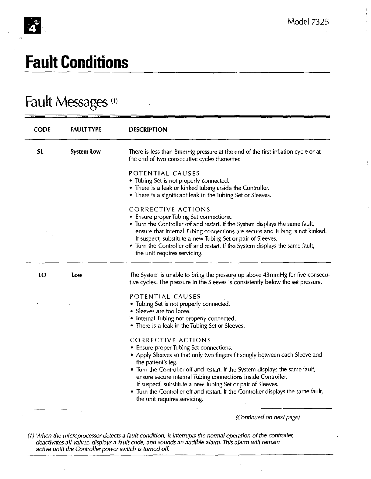
DESCRIPTION
There
is
less
the
end
of
two
POTENTIAL
¢
Tubing
e
There
+
There
CORRECTIVE
¢
Ensure
*
Тит
ensure
If
+
Turn
the
Set
is a leak
is a significant
proper
the
Controller
that
suspect,
the
Controller
unit
requires
than
8mmbHg
consecutive
CAUSES
is
not
or
pressure
properly
kinked
leak
ACTIONS
Tubing
internal
Set
off
and
Tubing
substitute a new
off
and
servicing.
at
the
cycles
thereafter.
connected.
tubing
inside
the
in
the
Tubing
connections.
restart.
If
the
connections
Tubing
restart.
Set
If
the
or
end
of
the
Controller.
Set
or
Sleeves.
System
are
System
secure
pair
of
displays
Sleeves.
displays
first
inflation
the
and
Tubing
the
cycle
same
is
same
or
fault,
not
kinked.
fault,
at
LO
(1)
When
deactivates
active
Low
the
microprocessor
all
valves,
until
the
Controller
The
tive
detects a fault
displays a fault
power
switch
System
cycles.
POTENTIAL
*
Tubing
*
Sleeves
*
Internal
*
There
CORRECTIVE
¢
Ensure
+
Apply
the
+
Turn
ensure
+
Turn
the
code,
Set
are too
Tubing
is a leak
proper
Sleeves
patients
the
secure
If
suspect,
the
unit
requires
condition,
and
sounds
is
turned
is
unable
The
is
to
bring
pressure
CAUSES
not
properly
loose.
not
properly
in
the
Tubing
ACTIONS
Tubing
so
that
Set
only
in
leg.
Controller
off
internal
substitute a new
Controller
off
servicing.
it
interrupts
an
audible
off.
the
pressure
the
Sleeves
connected.
`
connected.
Set
or
connections.
two
fingers
and
restart.
Tubing
connections
Tubing
and
restart.
the
normal
alarm.
up
above
is
consistently
Sleeves.
fit
snugly
If
the
System
inside
Set
or
pair
If
the
Controller
(Continued
operation
This
alarm
43mmHg
below
between
displays
Controller.
of
Sleeves.
displays
on
of
the
controller,
will
remain
the
each
the
next
for
five
set
Sleeve
same
the
same
page)
consecu-
pressure.
and
fault,
fault,
à
SCD
response”
Fault
CODE
SH
compression
system
Conditions
FAULT
TYPE
System
High
(conten)
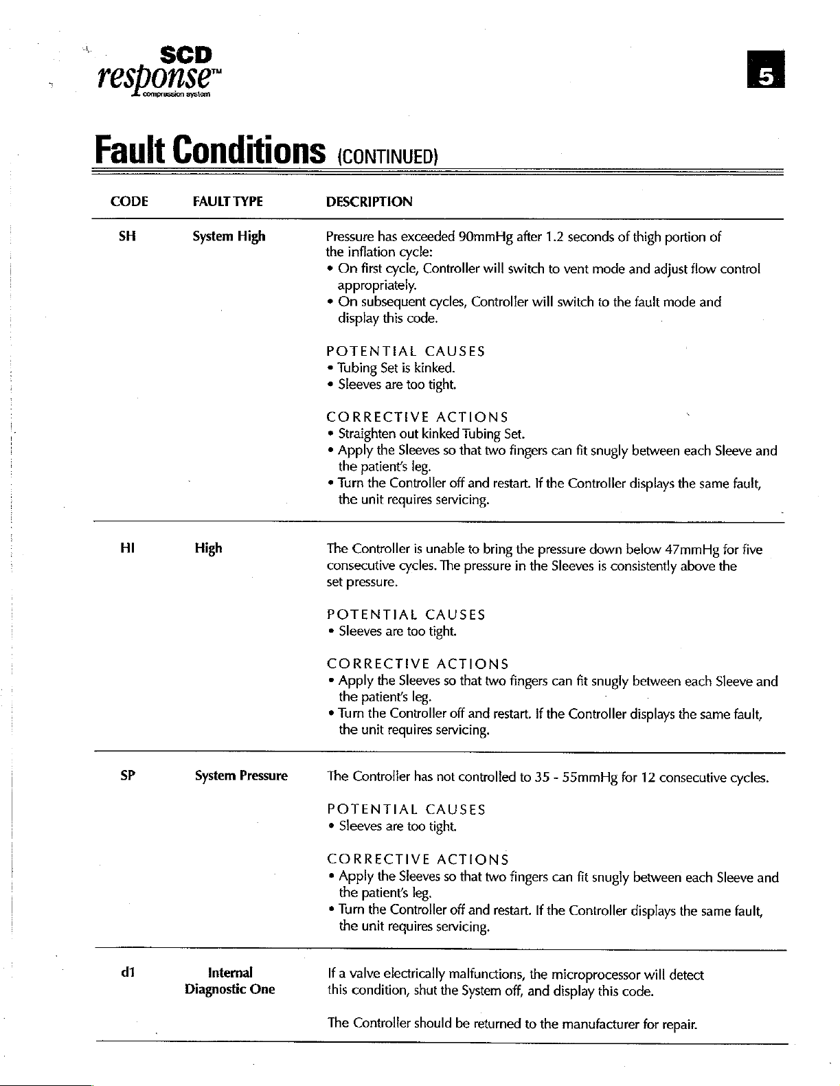
DESCRIPTION
Pressure
the
+
*
POTENTIAL
*
*
CORRECTIVE
*
*
+
has
exceeded
inflation
On
appropriately.
On
display
Tubing
Sleeves
Straighten
Apply
the
Turn
the
cycle:
first
cycle,
Controller
subsequent
this
code.
Set
is
kinked.
are
too
out
kinked
the
Sleeves
patients
the
unit
leg.
Controller
requires
CAUSES
tight.
cycles,
ACTIONS
servicing.
90mmHg
Controller
Tubing
so
that
off
and
after
will
switch
Set.
two
fingers
restart.
1.2
to
will
can
If
the
vent
switch
seconds
fit
Controller
of
mode
to
the
snugly
thigh
and
fault
between
displays
portion
adjust
flow control
mode
each
the
of
and
Sleeve
same
Fi
and
fault,
HI
SP
|
|
|
|
dí
High
System
Diagnostic
Pressure
Internal
One
The
Controller
consecutive
set
pressure.
POTENTIAL
©
Sleeves
CORRECTIVE
*
Apply
the
*
Turn
the
The
POTENTIAL
»
Sleeves
are
the
patients
the
Controller
unit
requires
Controller
are
CORRECTIVE
*
Apply
the
the
patients
*
Turn
the
Controller
the
unit
requires
If
a
valve
electrically
condition,
this
is
unable
cycles.
The
CAUSES
too
tight.
ACTIONS
Sleeves
leg.
servicing.
has
not
CAUSES
too
tight.
so
ACTIONS
Sleeves
so
leg.
servicing.
the
shut
to
bring
the
pressure
that
off
and
controlled
that
off
and
malfunctions,
System
in
two
fingers
restart.
to
two
fingers
restart.
off,
the
the
and
pressure
if
the
35
If
the
down
Sleeves
can
-
can
microprocessor
display
is
fit
snugly
Controller
55mmHg
fit
snugly
Controller
this
below
47mmHg
consistently
between
displays
for
between
displays
above
each
the
12
consecutive
each
the
will
detect
code.
for
the
Sleeve
same
Sleeve
same
five
and
fault,
cycles.
and
fault,
The
Controller
should
be
returned
to
the
manufacturer
for
repair.
Model
E
7325
Fault
CODE
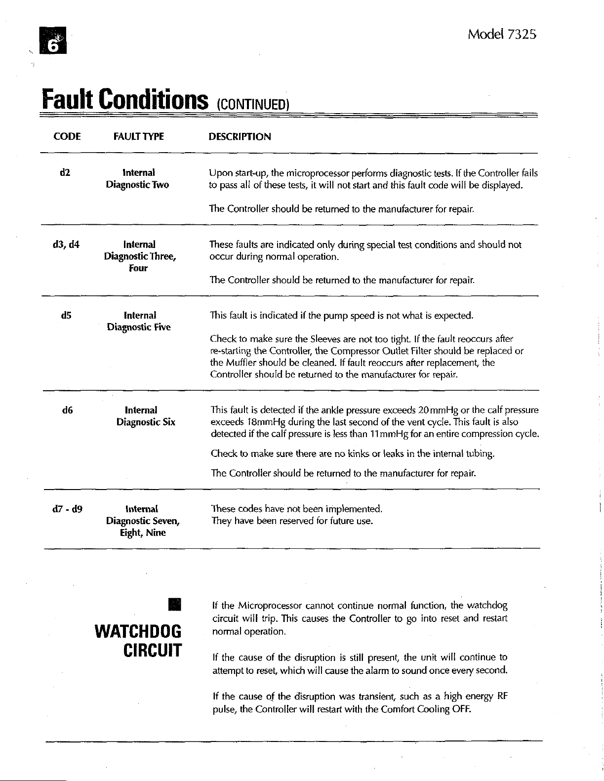
d2
d3,
d4
d5
Conditions
FAULT
TYPE
Internal
Diagnostic
Internal
Diagnostic
Diagnostic
Three,
Four
Internal
Two
Five
DESCRIPTION
Upon
to
The
These
occur
The
This
(сомпмиео)
start-up,
pass
all
Controller
faults
during
Controller
fault
Check
to
re-starting
the
Muffler
Controller
the
of
these
should
are
indicated
normal
should
is
indicated
make
sure
the
Controller,
should
should
microprocessor
tests,
it
be
operation.
be
if
the
the
Sleeves
be
cleaned.
be
returned
will
not
returned
only
during
returned
pump
speed
are
the
Compressor
If
fault
to
the
performs
start
to
to
not
diagnostic
and
this
the
manufacturer
special
the
manufacturer
test
manufacturer
is
not
too
tight.
Outlet
reoccurs
tests.
fault
code
for
conditions
for
what
is
expected.
If
the
fault
Filter
should
after
replacement,
for
repair.
If
the
Controller
will
be
repair.
and
should
repair.
reoccurs
be
replaced
fails
displayed.
not
after
or
the
47 - 09
de
Internal
Diagnostic
Six
internal
Diagnostic
Eight,
Seven,
Nine
WATCHDOG
CIRCUIT
This
fault
exceeds
detected
Check
The
These
They
if
circuit
normal
If
attempt
If
pulse,
18mmHg
if
to
Controller
codes
have
the
Microprocessor
will
operation.
the
cause
to
the
cause
the
is
detected
during
the
calf
make
sure
should
have
not
been
reserved
trip.
This
of
the
reset,
which
of
the
Controller
if
the
ankle
the
last
pressure
disruption
there
be
returned
been
for
cannot
causes
will
is
less
are
implemented.
future
the
cause
disruption
will
restart
pressure
second
than
no
kinks
to
the
use.
continue
Controller
is
still
the
alarm
was
transient,
with
the
exceeds
of
the
vent
11mmHg
or
manufacturer
normal
present,
leaks
to
the
to
sound
for
in
function,
go
such
Comfort
20
mmHg
cycle.
an
entire
the
internal
for
repair.
the
into
reset
unit
will
once
every
as a high
Cooling
or
the
calf
This
fault
is
compression
tubing.
watchdog
and
restart
continue
to
second.
energy
OFF.
RF
pressure
also
cycle.
|
i
}
 Loading...