

Tyco Electronics T208M-PRINTER, T208M-C-PRINTER, T212M-PRINTER, T212M-C-PRINTER System User's Manual
Page 1
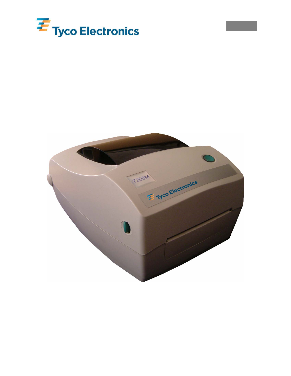
T200 SERIES THERMAL TRANSFER PRINTER
SYSTEM USER’S GUIDE
(T208M-PRINTER, T208M-C-PRINTER, T212M-PRINTER & T212M-C-PRINTER)
Page 2
T200 SERIES THERMAL TRANSFER PRINTER
SYSTEM USER’S GUIDE
(T208M-PRINTER, T208M-C-PRINTER, T212M-PRINTER & T212M-C-PRINTER)
APPROVALS NAME SIGNED DATE
TECHNICAL J. SWIFT
TECHNICAL SUPPORT J. SMITH
30/07/07
30/07/07
PRODUCT MANAGEMENT R. SWIFT
30/07/07
Revision History
Rev No CR No Date Incorporated By
1 Original Issue July 2002 Graham Leat & Mario Appello
2 Merged 4 languages November 2002 Jim Smith
3 Complete update March 2003 Graham Leat
4 Updated for New Model September 2004 Jim Smith
5 Made model have -Printer October 2004 Jim Smith
6 New logo & contents added July 2007 Jim Smith
7
8
9
Page 3

Contents
English .....................................................................................................................1
Forward ......................................................................................................................................2
Important Information!...............................................................................................................3
1.0 Printer Set-up..................................................................................................................4
1.1 Unpacking the Printer.................................................................................................4
1.2 Printer Overview ........................................................................................................5
1.3 Attaching the Power Supply To The Printer..............................................................6
1.4 Connecting the Interface Cable..................................................................................7
2.0 Ribbon Selection ............................................................................................................8
3.0 Loading Ribbon..............................................................................................................8
3.1 Adding a New Ribbon................................................................................................9
3.2 Removing a partially used Ribbon.............................................................................9
4.0 Loading Product...........................................................................................................10
4.1 Loading TMS Marker Sleeves .................................................................................11
4.2 Loading Labels.........................................................................................................12
4.3 Loading Product Cont… ..........................................................................................13
5.0 Calibration....................................................................................................................14
5.1 Alignment For Calibration .......................................................................................15
6.0 Changing Sensor Type .................................................................................................16
6.1 Reflective (Black Mark) Sensor...............................................................................16
6.2 Continuous Sensing Mode........................................................................................16
6.3 Transmissive Sensor.................................................................................................16
7.0 Printer Firmware Versions ...........................................................................................16
8.0 Software........................................................................................................................17
9.0 Print Quality.................................................................................................................17
10.0 Maintenance .................................................................................................................18
10.1 Cleaning the Print Head ...........................................................................................18
10.2 Cleaning the Platen Roller........................................................................................19
11.0 Troubleshooting............................................................................................................20
Appendix A ..............................................................................................................................21
T200 Series with Cutter........................................................................................................21
Clearing the Media Cutter....................................................................................................22
Appendix B...............................................................................................................................23
Interface Cable Wiring.........................................................................................................23
Francàis .................................................................................................................26
Avant-propos............................................................................................................................27
Information importante !..........................................................................................................28
1.0 Installation de l’imprimante .........................................................................................29
1.1 Déballage de l’imprimante.......................................................................................29
1.2 Vue d’ensemble de l’imprimante.............................................................................30
1.3 Branchement de l’adaptateur d’alimentation électrique de l’imprimante................31
1.4 Connexion du câble d’interface................................................................................32
2.0 Choix du ruban.............................................................................................................33
3.0 Chargement du ruban ...................................................................................................33
Page 4

3.1 Insertion d’un ruban neuf.........................................................................................34
3.2 Retrait d’un ruban partiellement usagé ....................................................................34
4.0 Chargement du produit.................................................................................................35
4.1 Chargement des manchons de marquage TMS........................................................36
4.2 Chargement d’étiquettes...........................................................................................37
4.3 Chargement du produit (suite)..................................................................................38
5.0 Calibrage ......................................................................................................................39
5.1 Alignement de calibrage...........................................................................................40
6.0 Changement du type de capteur ...................................................................................41
6.1 Capteur réflectif (marque noire)...............................................................................41
6.2 Mode de détection continue .....................................................................................41
6.3 Capteur transmissif...................................................................................................41
7.0 Versions du micrologiciel de l’imprimante..................................................................41
8.0 Logiciel.........................................................................................................................42
9.0 Qualité d’impression ....................................................................................................42
10.0 Entretien .......................................................................................................................43
10.1 Nettoyage de la tête d’impression ............................................................................43
10.2 Nettoyage du rouleau de la platine...........................................................................44
11.0 Dépannage....................................................................................................................45
Annexe A..................................................................................................................................46
Série T200 avec massicot.....................................................................................................46
Déblocage du massicot de support.......................................................................................47
Annexe B..................................................................................................................................48
Câblage du câble d’interface................................................................................................48
Deutsch...................................................................................................................51
Vorwort ....................................................................................................................................52
Wichtige Information!..............................................................................................................53
1.0 Aufbau des Druckers....................................................................................................54
1.1 Den Drucker auspacken............................................................................................54
1.2 Überblick über den Drucker.....................................................................................55
1.3 Anschluss des Druckers an die Stromversorgung....................................................56
1.4 Anschluss des Interface-Kabels................................................................................57
2.0 Auswahl des Farbbands................................................................................................58
3.0 Einlegen des Farbbands................................................................................................58
3.1 Ein neues Farbband einlegen....................................................................................59
3.2 Entfernen eines teilweise gebrauchten Farbbands ...................................................59
4.0 Einlegen von Druckmedien..........................................................................................60
4.1 Einlegen der TMS Markierungsbanderolen.............................................................61
4.2 Einlegen von Etiketten .............................................................................................62
4.3 Einlegen von Druckmedien Fortsetzung..................................................................63
5.0 Kalibrierung..................................................................................................................64
5.1 Ausrichtung zur Kalibrierung...................................................................................65
6.0 Wechsel des Sensortyps ...............................................................................................66
6.1 Reflektionssensor (schwarze Markierung)...............................................................66
6.2 Endlosdruck-Sensor..................................................................................................66
6.3 Sensor für lichtdurchlässige Druckmedien...............................................................66
Page 5

7.0 Drucker-Firmware-Versionen......................................................................................67
8.0 Software........................................................................................................................67
9.0 Druckqualität................................................................................................................67
10.0 Wartung........................................................................................................................68
10.1 Reinigung des Druckkopfes .....................................................................................68
10.2 Reinigung der Walzenrolle.......................................................................................69
11.0 Fehlerbehebung............................................................................................................70
Anhang A .................................................................................................................................71
T200 Serie mit Schneideinrichtung......................................................................................71
Reinigen der Schneideinrichtung .........................................................................................72
Anhang B..................................................................................................................................73
Interfacekabel-Verdrahtung..................................................................................................73
Español...................................................................................................................76
Objeto.......................................................................................................................................77
Información importante............................................................................................................78
1.0 Configuración de la impresora.....................................................................................79
1.1 Desembalaje de la impresora....................................................................................79
1.2 Visión de conjunto de la impresora..........................................................................80
1.3 Conexión de la impresora a la red eléctrica .............................................................81
1.4 Conexión del cable de interfaz.................................................................................82
2.0 Selección de cinta.........................................................................................................83
3.0 Carga de la cinta...........................................................................................................83
3.1 Adición de una nueva cinta......................................................................................84
3.2 Retirada de una cinta parcialmente usada ................................................................84
4.0 Carga del producto .......................................................................................................85
4.1 Carga de las fundas para marcar TMS .....................................................................86
4.2 Carga de las etiquetas...............................................................................................87
4.3 Carga del producto cont. ..........................................................................................88
5.0 Calibrado......................................................................................................................89
5.1 Alineación para el calibrado.....................................................................................90
6.0 Cambio del tipo de sensor............................................................................................91
6.1 Sensor reflectante (marca negra)..............................................................................91
6.2 Modo de detección continua.....................................................................................91
6.3 Sensor transmisor.....................................................................................................91
7.0 Versiones de microprogramación de la impresora.......................................................91
8.0 Software........................................................................................................................92
9.0 Calidad de impresión....................................................................................................92
10.0 Mantenimiento..............................................................................................................93
10.1 Limpieza del cabezal de impresión ..........................................................................93
10.2 Limpieza del rodillo de platina.................................................................................94
11.0 Resolución de problemas..............................................................................................95
Apéndice A...............................................................................................................................96
Serie T200 con guillotina.....................................................................................................96
Retirada de residuos de la guillotina ....................................................................................97
Apéndice B...............................................................................................................................98
Instalación del cable de interfaz...........................................................................................98
Page 6
English
English
T200 SERIES THERMAL TRANSFER PRINTER
SYSTEM USER’S GUIDE
(T208M-PRINTER, T208M-C-PRINTER,T212M-PRINTER & T212M-C-PRINTER)
EIL/MAN/002: REVISION 6 Date: July 2007 Page 1
Page 7
English
Forward
This manual provides installation and operation information for the T208M-PRINTER (E63660-
000), T208M-C-PRINTER (D82271-000), T212M-PRINTER (E23401-000) and T212M-CPRINTER (A53989-000), manufactured for Tyco Electronics.
Copyright Notice
This document contains information proprietary to Tyco Electronics. This document and
information contained within is copyrighted by Tyco Electronics and may not be duplicated in
full or in part by any person without written approval from Tyco Electronics. While every effort
has been made to keep the information contained within current and accurate as of the date of
publication, no guarantee is given or implied that the document is error-free or that it is accurate
with regard to any specification. Tyco Electronics reserve the right to make changes, for the
purpose of product improvement, at any time.
Trademarks
T208M and T212M are service trademarks of Tyco Electronics. Windows and MS-DOS are
registered trademarks of Microsoft Corp. All other marks are trademarks or registered
trademarks of their respective holders.
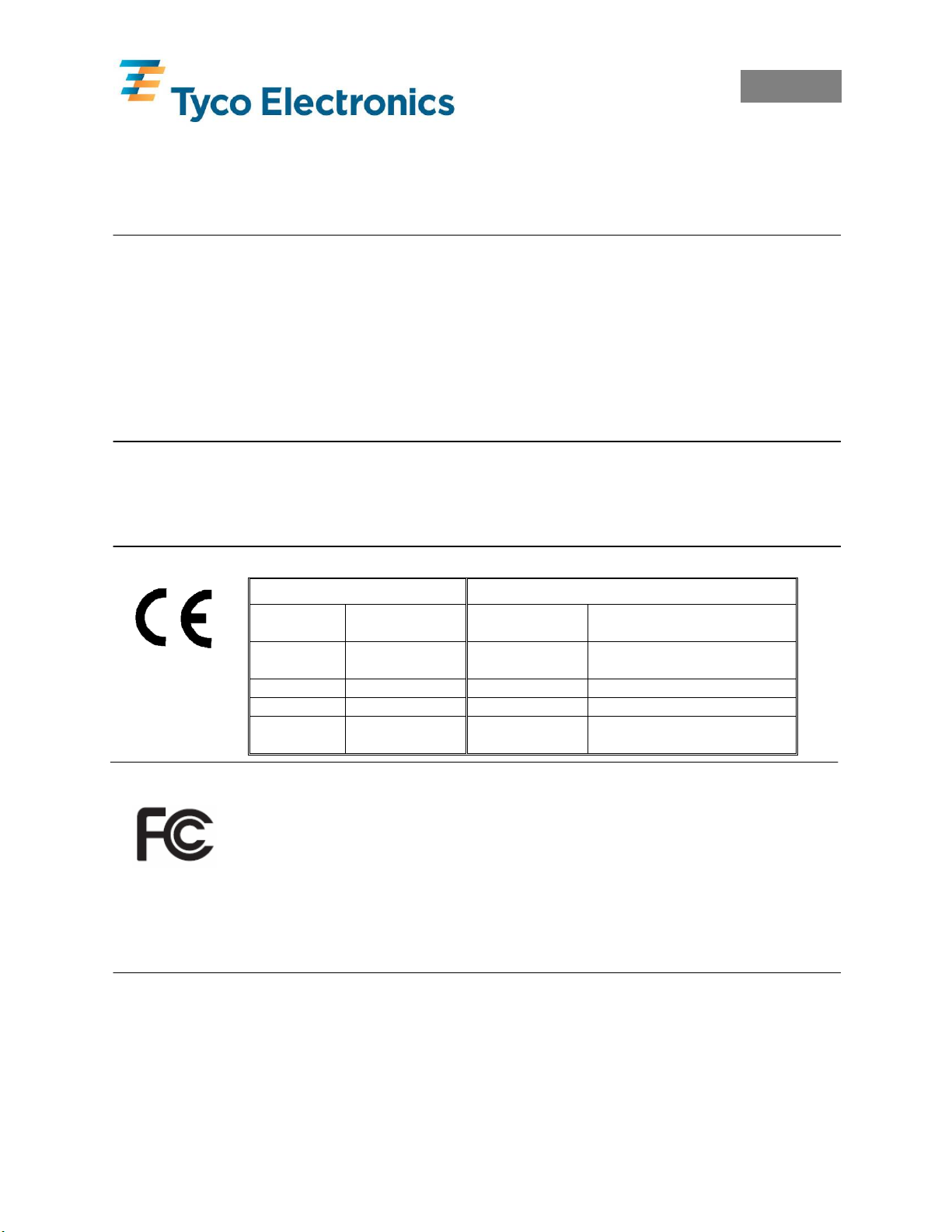
T208M-PRINTER, T208M-C-PRINTER, T212M-PRINTER and T212M-C-PRINTER Thermal Printers
European Council Directive Compliance to Standards
89/336/EEC EMC Directive
EMC Directive EN 55024 1988
92/31/EE EMC Directive EN 61000-3-2 Harmonic Emissions
92/31/EE EMC Directive EN 61000-3-3 Voltage Variation
CB Scheme
FCC – Declaration of Conformity
Models: T208M-PRINTER, T208M-C-PRINTER, T212M-PRINTER and
T212M-C-PRINTER conform to the following specifications: FCC Part 15,
Subpart B, Section 15.107(a) and Section 15.109(a) Class B digital device.
Supplimental Information:
This device complies with part 15 of the FCC Rules. Operation is subject to the following Two Conditions: (1)
This device may not cause harmfull interference, and (2) this device must accept any interference received,
including interference that may cause undesired operation.
Industry Canada Notice:
This device complies with Industry Canada ICS-003 class B requirements.
Cet equipment est conforme a l’ICS-003 classse B de la norm Industrielle Canadian.
EN 55022-B
1988
EN 60950 1991
A1, A2, A3, A4
RF Emissions control
Immunity to Electro-magnetic
Disturbances
Safety
EIL/MAN/002: REVISION 6 Date: July 2007 Page 2
Page 8
English
Important Information!
Incorrect use of this equipment can cause injury. It is advised that operators be trained in
the correct use of the equipment and that they read this manual before use.
Maintenance must only be carried out by suitably qualified and trained personnel.
Shock Hazard Warning:
The printer and power supply should never be operated in a location where either one
can get wet. Personal injury could result.
Media and Ribbon Warning:
Always use high quality, approved product and ribbons. If adhesive backed labels are
used the DO NOT lay flat on the backing liner, the exposed edges may stick to the label
guides and rollers inside the printer, causing the label to peel off from the liner and jam
the printer. Permanent damage to the print head may result if a non-approved ribbon is
used as it may be wound incorrectly for the printer or contain chemicals corrosive to the
print head. Approved supplies can be ordered from your dealer.
Reloading Hint:
If labels or ribbon run out while printing, DO NOT turn the power switch OFF (0) while
reloading or data loss may result. The printer automatically restarts after you load a new
label or ribbon roll
Static Discharge:
The discharge of electrostatic energy that accumulates on the surface of the human body
or other surfaces can damage or destroy the print head or electronic components used in
this device. DO NOT TOUGH the print head or the electronic components under the top
cover.
Thermal Printing:
The print head becomes hot while printing. To protect from damage the print head and
risk of personal injury, avoid touching the print head. Use only the cleaning pen or IPA
wipes to perform maintenance.
Product and Ribbon Storage:
All products and ribbons must be kept in a clean area, free from contamination, dust,
grease and condensation. Image quality and durability may be affected if this is not the
case. Storage conditions and shelf-life are marked on each product container. For
further information please contact Tyco Electronics.
EIL/MAN/002: REVISION 6 Date: July 2007 Page 3
Page 9

English
1.0 Printer Set-up
1.1 Unpacking the Printer
Unpack the printer ensuring that all packaging is retained for future transit. In the unlikely
event of the printer arriving in a less than perfect state, please contact your Tyco Electronics
representative or the shipping agent.
The following should be included with the printer:
• Three power leads: UK, European, US.
• Parallel communications cable.
• Power supply.
• Spare cardboard core (for ribbon take-up).
• Print head cleaning pen.
• Tyco Electronics CD ROM containing…
o Electronic Copy of this User Guide.
o Printer Drivers for Windows 95, 98, Me, NT4, 2K and XP.
o Font Downloader .
o Firmware Downloader – Only to be used when advised by Tyco Electronics.
o Wintotal Demo Software.
o PrintEasy Demo Software.
• Tyco Electronics print contrast scale.
EIL/MAN/002: REVISION 6 Date: July 2007 Page 4
Page 10
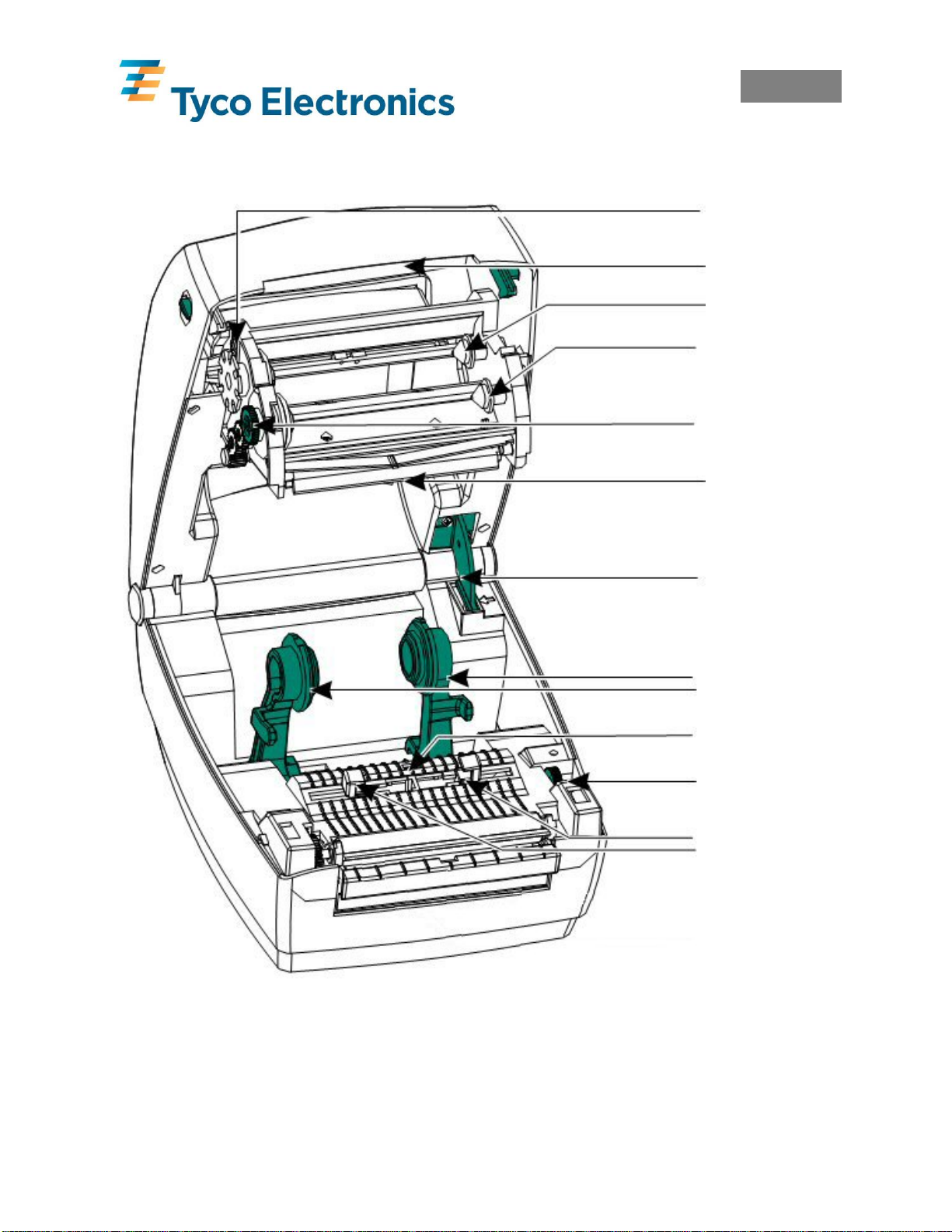
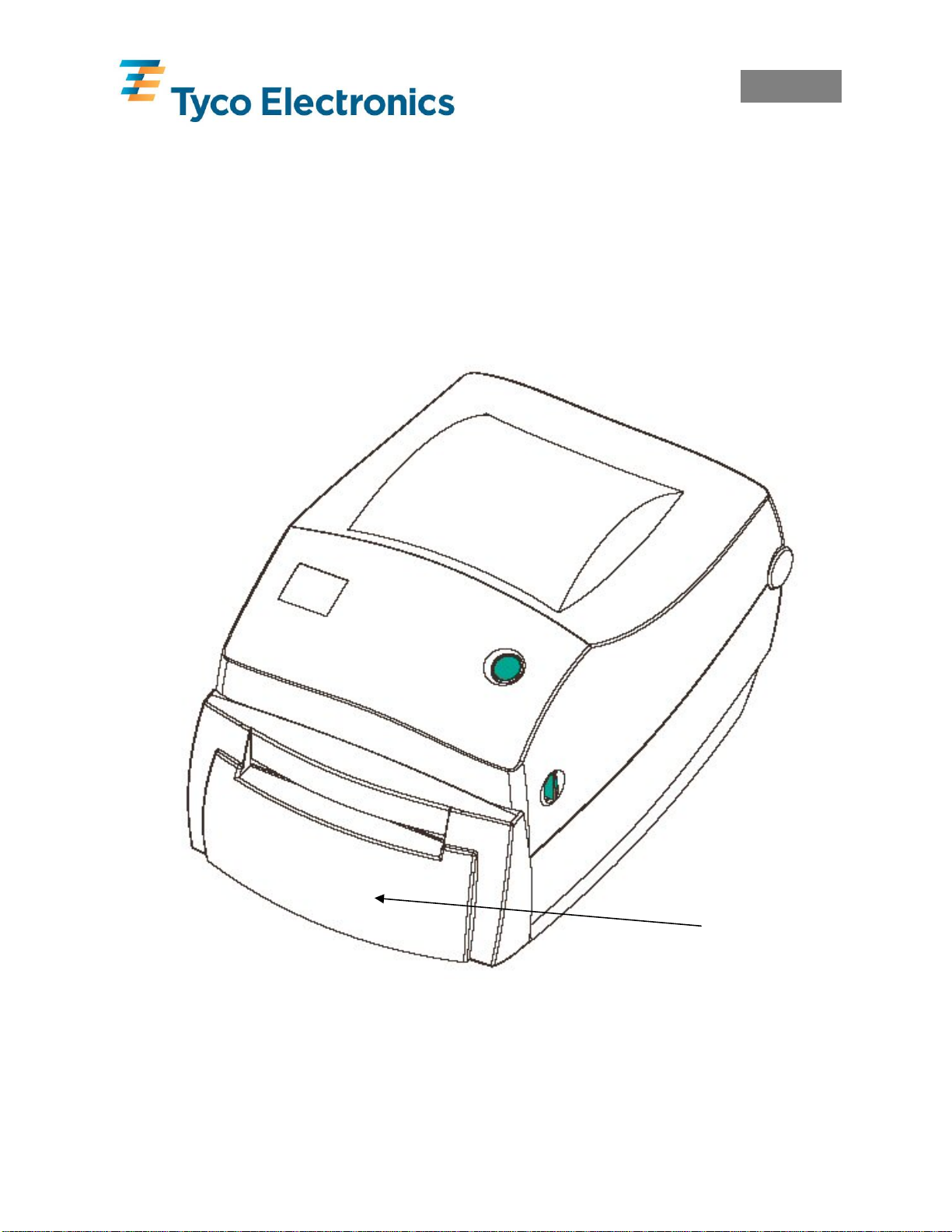
1.2 Printer Overview
English
Supply Ribbon Hub
Take-Up Ribbon Hub
Ribbon Take-Up Gear
Top Cover Lock
Media Roll Holders
Media Sensor
EIL/MAN/002: REVISION 6 Date: July 2007 Page 5
Guides Adjustment
Media Guides
Page 11
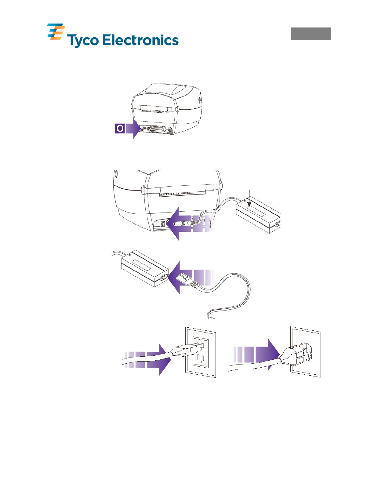
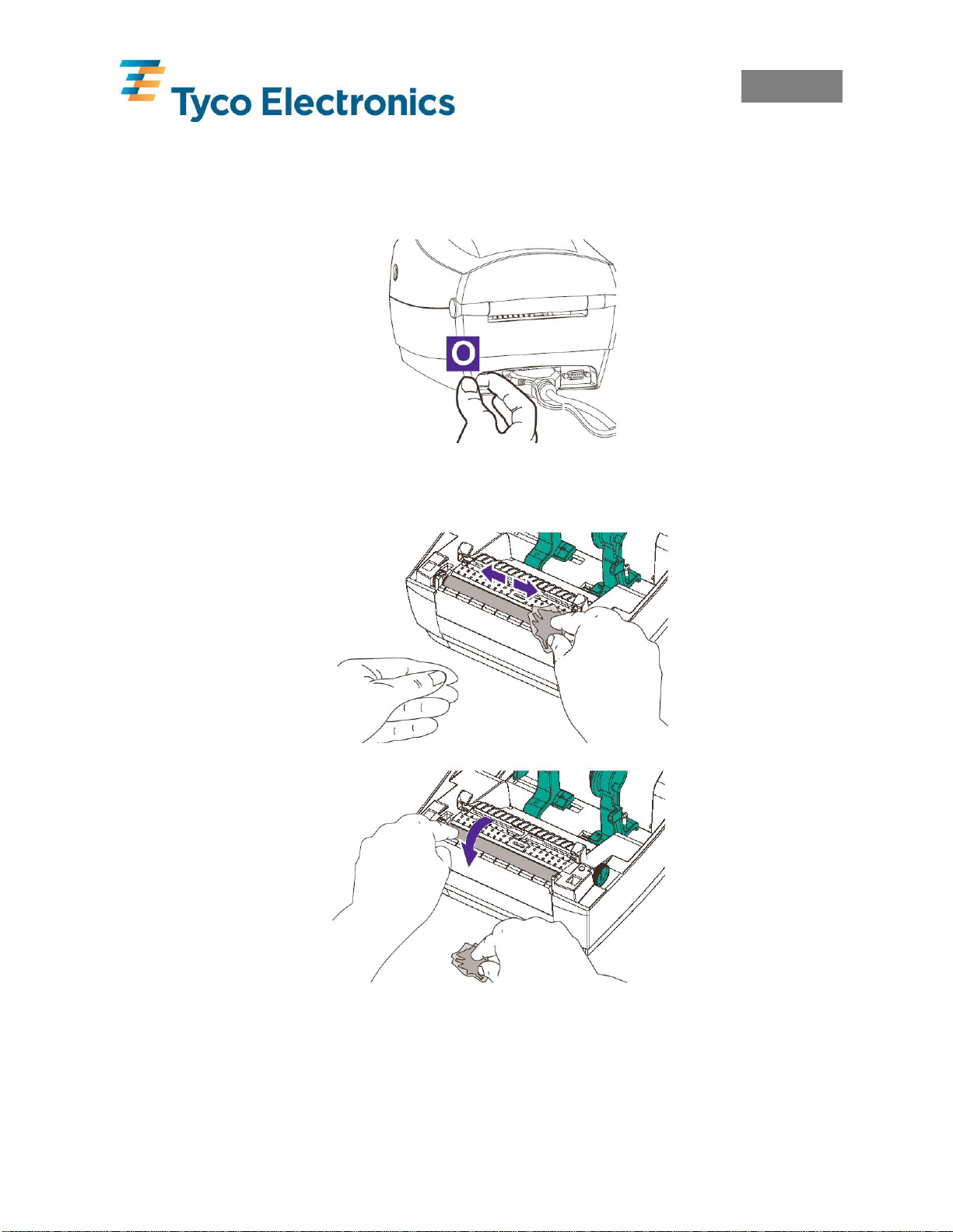
1.3 Attaching the Power Supply To The Printer
Power OFF
Check Voltage
Plug In Power
Module
Plug in Power Cord
Plug Power Cord
into a Suitable AC
Outlet
English
EIL/MAN/002: REVISION 6 Date: July 2007 Page 6
Page 12
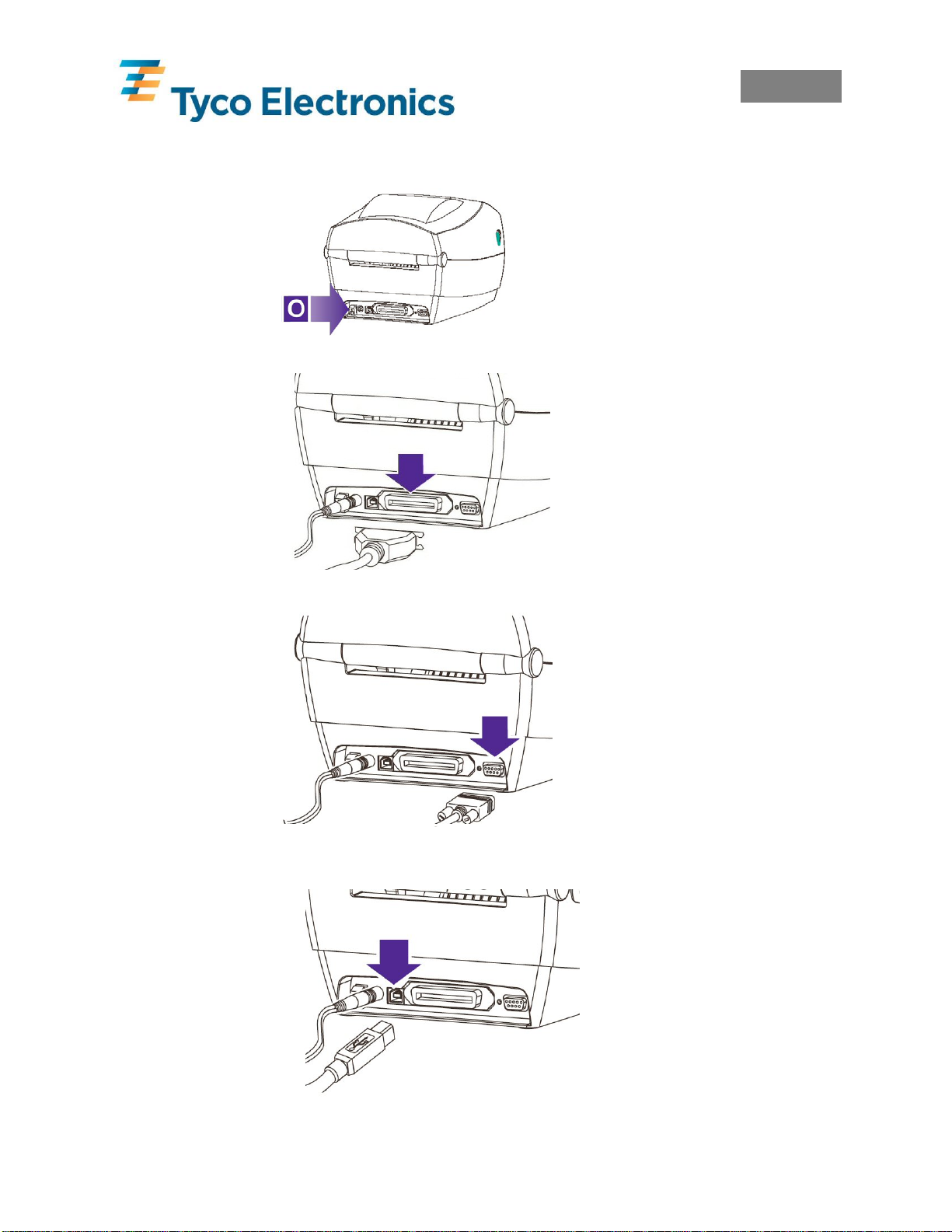
1.4 Connecting the Interface Cable
Power OFF
Parallel
Serial
USB
(Universal
Serial Bus)
English
EIL/MAN/002: REVISION 6 Date: July 2007 Page 7
Page 13
English
2.0 Ribbon Selection
Print quality and permanency on Tyco Electronics Identification products is only guaranteed if
the correct thermal transfer ribbon is used for each product. Please refer to the
“Printer/material/ribbon compatibility cross reference” found at
Tyco Electronics.
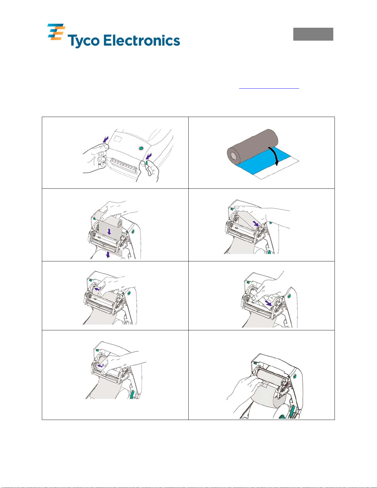
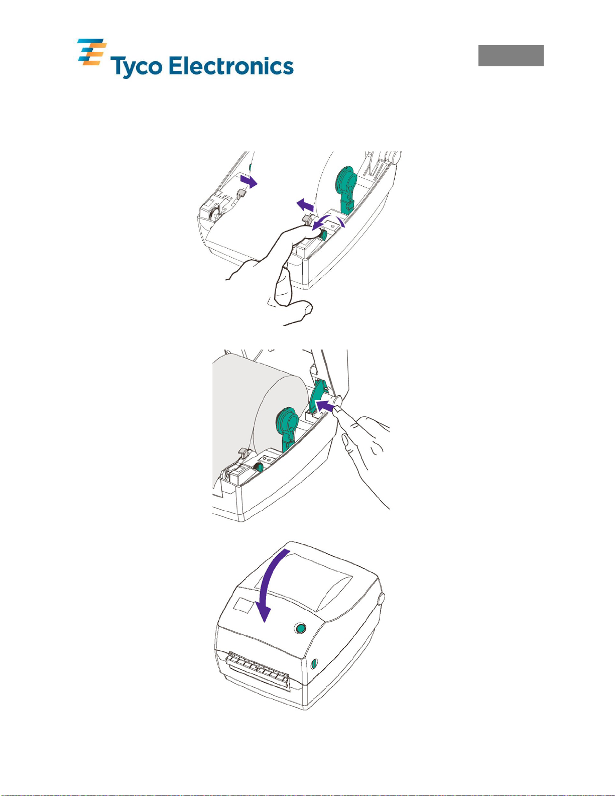
3.0 Loading Ribbon
1. Open Cover.
2. Pull Adhesive Strip Free on ribbon.
www.tycoident.com or contact
3. Thread the ribbon through carriage.
5. Align Notches onto Hub Spokes.
7. Align Notches onto Hub Spokes.
4. Press core onto Hub.
6. Press the take-up core on to the Hub.
8. Attache ribbon to take-up core using
adhesive strip on new ribbons or tape.
EIL/MAN/002: REVISION 6 Date: July 2007 Page 8
Page 14
English
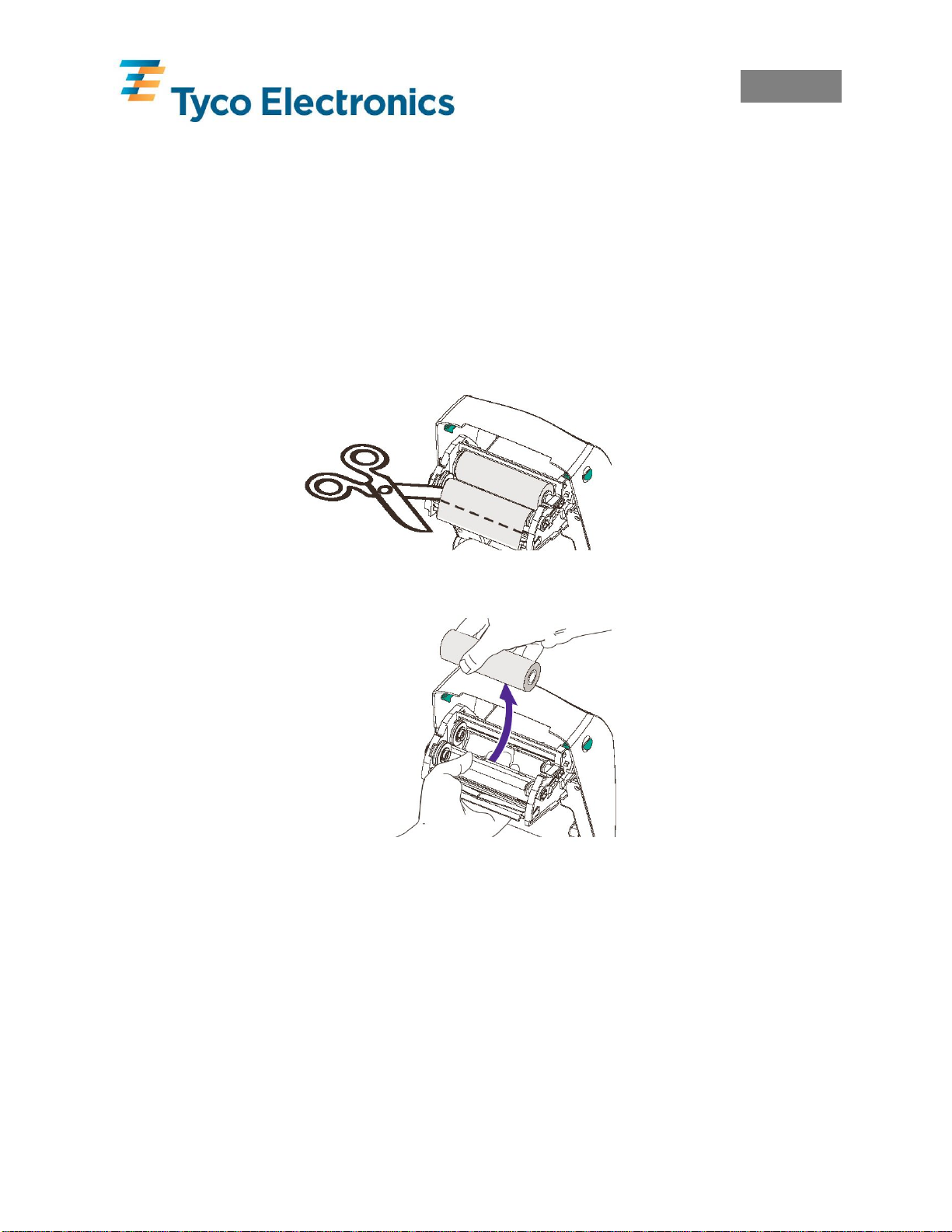
3.1 Adding a New Ribbon
If while printing the ribbon runs out, the indicator lights orange and the printer pauses. Keeping
the power ON, open the top cover. Cut the used ribbon so both cores can be removed. Load the
new ribbon as described in section 3.0 Loading Ribbon. Close the top cover and press the feed
button to restart printing.
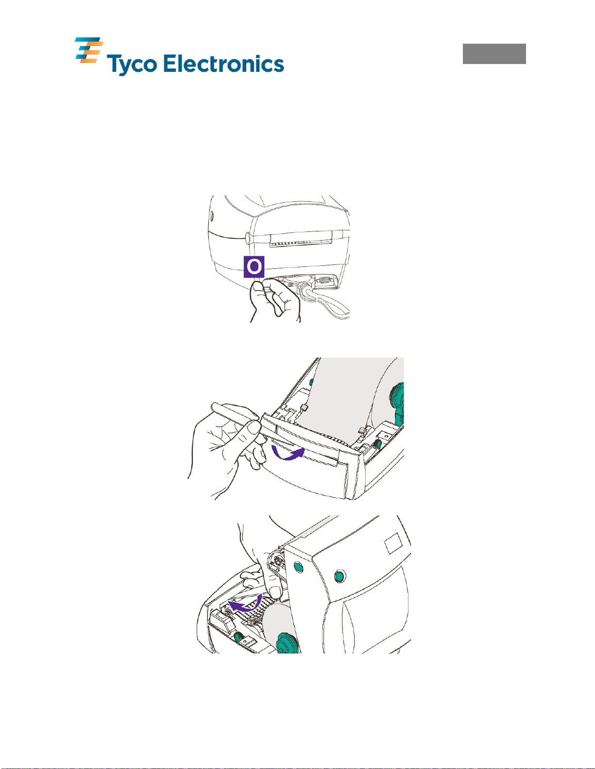
3.2 Removing a partially used Ribbon
To remove a partially used ribbon cut the ribbon from the take-up roll. Remove the take-up roll.
Remove all the used ribbon from the take-up core and keep the empty core for future use.
Remove the supply roll and store in accordance with the ribbons storage conditions.
Cut Used Ribbon from Supply
Push Supply Roll
Out
Important Note: When a complete ribbon has been used, the take-up roll must be replaced with
an empty cardboard roll, or the waste ribbon must be removed from the take-up cardboard core.
Allowing the waste ribbon to build up on the take-up cardboard core can rub against the new
ribbon and jam.
EIL/MAN/002: REVISION 6 Date: July 2007 Page 9
Page 15
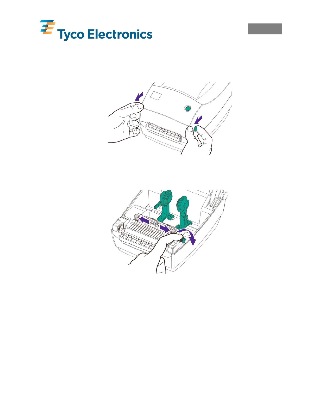
4.0 Loading Product
Open Cover
Open Guides
English
EIL/MAN/002: REVISION 6 Date: July 2007 Page 10
Page 16

English
4.1 Loading TMS Marker Sleeves
TMS marker sleeves can be loaded either internally or externally. Both methods require the
Media Roll Holders to be held open and the locking screw tightened using a screwdriver.
4.1.1 TMS Marker Sleeves Internal Loading
Remove all packaging and the large cardboard core and place the product loose into the media
bay of the printer. This is suitable for TMS marker sleeves and some self-adhesive label
products with large cardboard cores.
4.1.2 TMS Marker Sleeves External Loading
Product can be fed into the printer via the rear access slot at the back of the printer. This is
suitable if it is desired to leave TMS marker sleeves in the cardboard box they are shipped in.
EIL/MAN/002: REVISION 6 Date: July 2007 Page 11
Page 17
English
4.2 Loading Labels
Labels can be loaded either internally or externally.
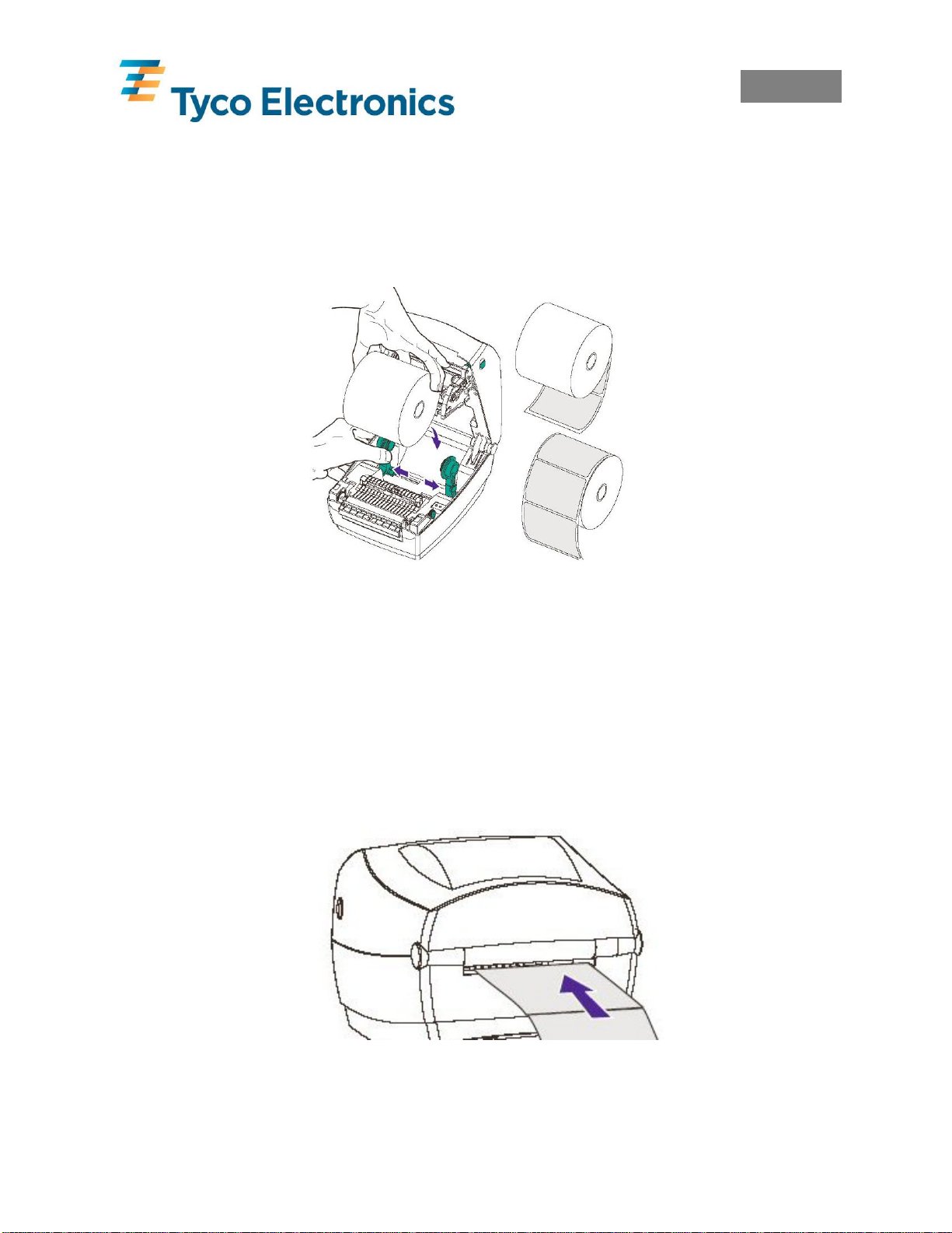
4.2.1 Labels Internal Loading
Labels supplied on small cardboard cores can be held in place by the spring loaded Media Roll
Holders.
Labels that do not fit the Media Roll Holders can be removed from their core and placed loose
in the media bay of the printer. The Media Roll Holders must be locked open for this option,
see section 4.1 Loading TMS Marker Sleeves.
4.2.2 Labels External Loading
Labels can be fed into the printer via the rear access slot at the back of the printer. This is
suitable if the labels do not fit the internal Media Roll Holders. A suitable media holder should
be used. Please contact Tyco Electronics for more details.
EIL/MAN/002: REVISION 6 Date: July 2007 Page 12
Page 18
English
4.3 Loading Product Cont…
The first marker sleeve/label must be positioned on the black rubber pinch roller. Once loaded
close the media guides to lightly grip the product.
Release Cover
Close Cover
EIL/MAN/002: REVISION 6 Date: July 2007 Page 13
Page 19
English
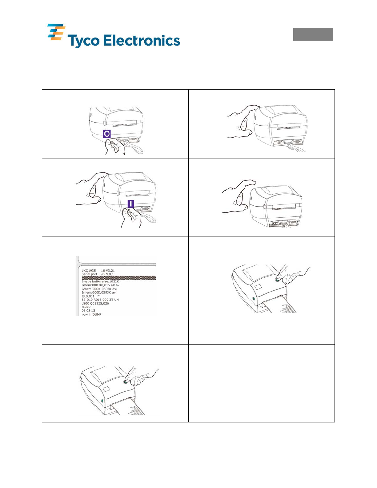
5.0 Calibration
When loading new or changing product types the printer must be calibrated.
Once the product and ribbon are correctly installed, the following procedure must be carried out
1. Power Off.
3. Holding Down Feed Button, Power On.
5. Printer Advances Media and Prints
Status Summary.
Note: Printer is in diagnostic dump mode. The
first line printed on the printout during calibration
will be the firmware version.
7. Each press of the feed button should
then advance one marker sleeve/label.
2. Hold Down Feed Button.
4. Once LED Flashes Red 3 times release
Feed Button.
6. Press Feed Button to Begin Normal
Operation.
Note:
If the printer continuously feeds or feeds more
than one marker sleeve or label at a time, or
the LED remains orange or red then refer
section 5.1 Alignment for Calibration and 11.0
Troubleshooting and then repeat the procedure
calibration procedure .
EIL/MAN/002: REVISION 6 Date: July 2007 Page 14
Page 20
English
5.1 Alignment For Calibration
Calibration on some products can prove difficult to achieve. This is normally due to the sensor
timing out before the label and backing material contrast has been recognised by the printer’s
sensor.
Reducing the length of time the sensor has to pick up on the difference between the labels and
backing material will result in successful sensor calibrations.
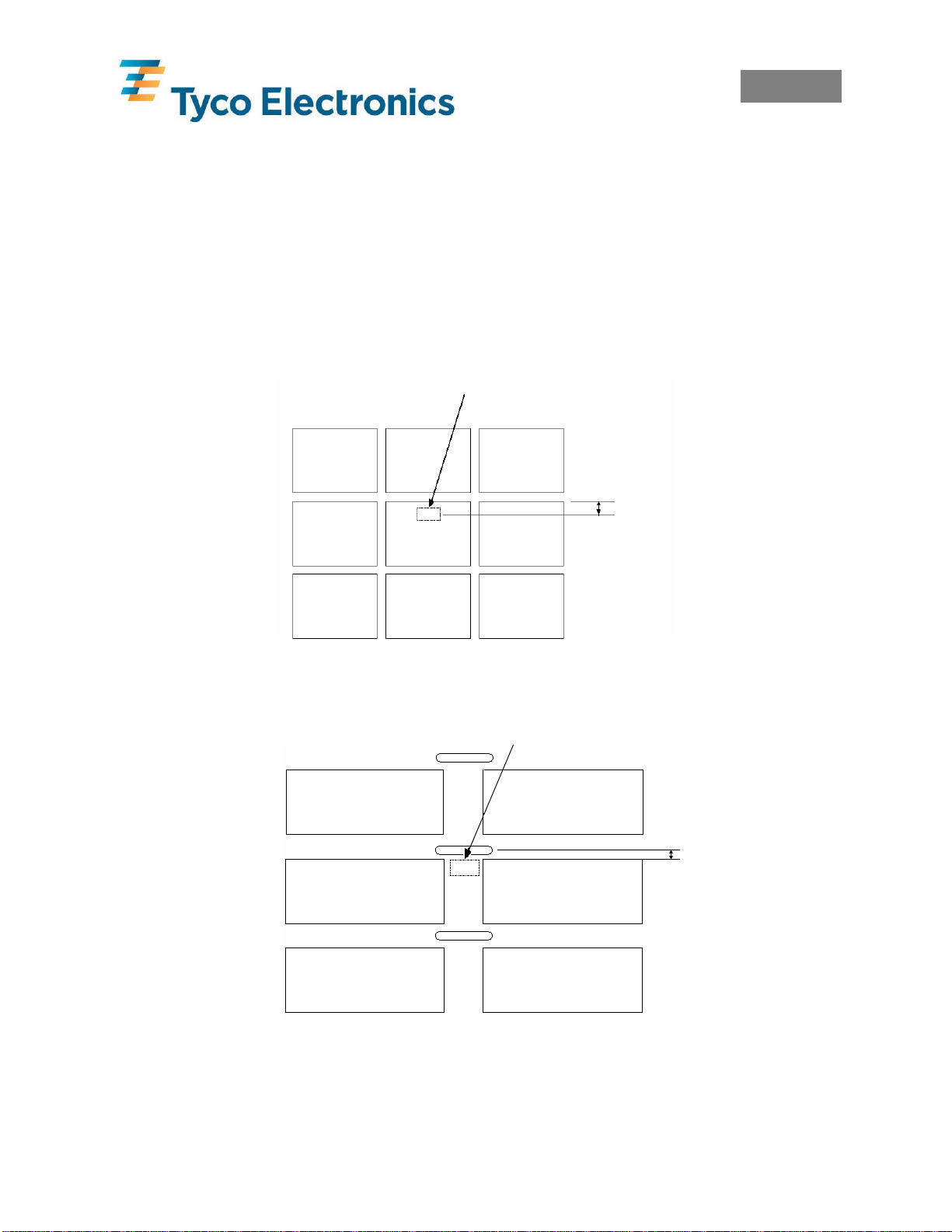
5.1.1 Labels Alignment
Position a label under the T200 sensor with less than approx. 5mm of label travel to occur
before the backing material is picked up by the sensor.
Approx 5mm
5.1.2 Labels With Sensor Holes Alignment
Position a label under the T200 sensor with less than approx. 5mm of media travel to occur
before the sensor hole is picked up by the sensor.
NOTE: Labels will only calibrate if they pass directly under the sensor. Products that do not
have a label directly under the sensor will not calibrate. A sensor hole or black mark is required
to calibrate these products. If the black mark is to be used the default sensor setting must be
changed in the printer, refer to section 6.0 Changing Sensor Type.
AApprox 5mm
EIL/MAN/002: REVISION 6 Date: July 2007 Page 15
Page 21

English
6.0 Changing Sensor Type
The default sensor for the T200 is the Transmissive Sensor (Web) sensor. This should work for
all TMS products and standard labels. If the Reflective (Black Mark) sensor is required or
Continuous mode is required then the relevant procedures must be carried out.
6.1 Reflective (Black Mark) Sensor
To enable the Reflective (Black Mark) sensor a label must be printed to the printer with the
sensor set to Reflective (Black Mark) in either Wintotal via Advanced Label Editing or
PrintEasy’s Windows Printer Driver. Once a label with these settings has been sent to the
printer, the LED will display Red. The printer must then be calibrated on the Reflective (Black
Mark) product.
6.2 Continuous Sensing Mode
To enable continuous products to be printed the printer must be put into continous mode. To
enable this a label must be printed to the printer with the sensor set to Continuous in either
Wintotal via Advanced Label Editing or PrintEasy’s Windows Printer Driver. Once a label
with these settings has been sent to the printer the LED will display Red. The printer must then
be calibrated on the continuous product.
6.3 Transmissive Sensor
To return to the Transmissive (Web) sensor a label must be printed to the printer with the sensor
set to Transmissive (Web) in either Wintotal via Advanced Label Editing or PrintEasy’s
Windows Printer Driver. Once a label with these settings has been sent to the printer, the LED
will display Red. The printer must then be calibrated on the Transmissive (Web) product.
Note: The calibration process is the same for all sensing modes and is described in section 5.0
Calibration.
7.0 Printer Firmware Versions
The printers will come pre-loaded with the correct firmware version:
T208M & T208M-C - firmware version 4.51 or newer.
T212M & T212M-C - firmware version 4.51 or newer.
The firmware version should not be changed or updated without checking with Tyco
Electronics. Not all versions of firmware will allow for the successful printing of Tyco
Electronics identification products.
The firmware version can be checked by undertaking a printer calibration. (see section 5.0
Calibration)
EIL/MAN/002: REVISION 6 Date: July 2007 Page 16
Page 22

English
8.0 Software
The recommended software for printing on the T200 series is either WinTotal for TMS markers
and basic Label design or PrintEasy for Labels. Demonstration versions of both these packages
can be found on the CD.
WinTotal has built in printer drivers.
PrintEasy uses Windows Printer Drivers – they can be installed automatically from the CD.
These drivers will work on Windows 95, 98, Me, NT4, 2K and XP
Both software programs can control all relevant aspects of the printer including Speed and
Darkness. Most products will print successfully with the default settings from either software
package. Increasing the Darkness will normally improve the print quality.
Note: For more details please refer to the software documentation or contact your local Tyco
Electronics representative.
9.0 Print Quality
To ensure that the correct print quality is achieved the printed product should have a minimum
contrast value of 8 (preferably 9-10) on the Tyco Electronics print contrast scale.
EIL/MAN/002: REVISION 6 Date: July 2007 Page 17
Page 23
English
10.0 Maintenance
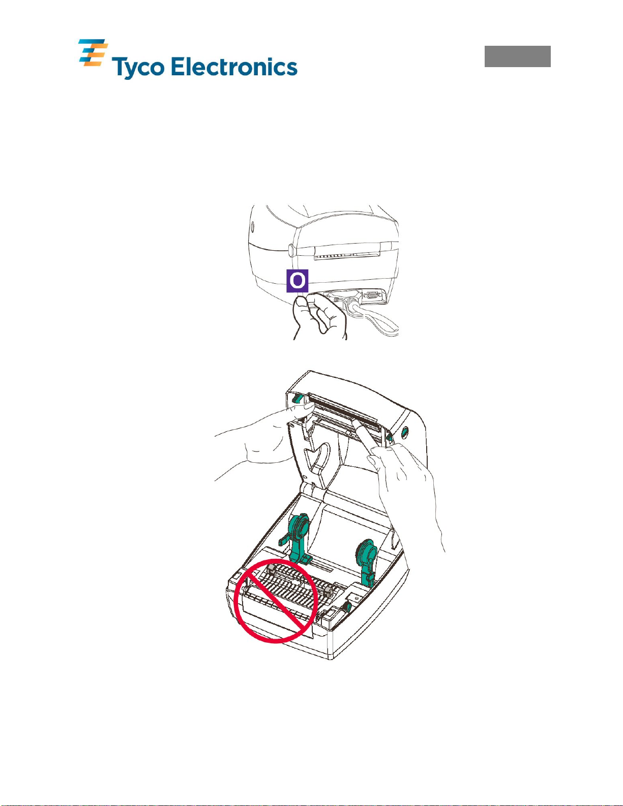
10.1 Cleaning the Print Head
It is recommended that the print head be cleaned after a roll of ribbon is consumed. This should
be done using the print head cleaning pen shipped with the printer or any standard thermal
transfer print head cleaning product (for example, an IPA wipe).
Turn Printer OFF
Rub Cleaning Pen
Across Dark Area of
Print Head
Do Not Clean Platen
Roller with
Cleaning Pen
EIL/MAN/002: REVISION 6 Date: July 2007 Page 18
Page 24
English
10.2 Cleaning the Platen Roller
Over time the platen picks up adhesive dust which requires occasional cleaning. This can
be done using a clean lint-free cloth lightly moistened with isopropyl alcohol.
Turn Printer OFF
Unplug all power
and interface leads.
Gently wipe top of
platen
Advance platen
One-Sixth (1/6) turn
Repeat steps until
platen is clean
Note: Let the platen dry for at least one minute before loading media.
EIL/MAN/002: REVISION 6 Date: July 2007 Page 19
Page 25
English
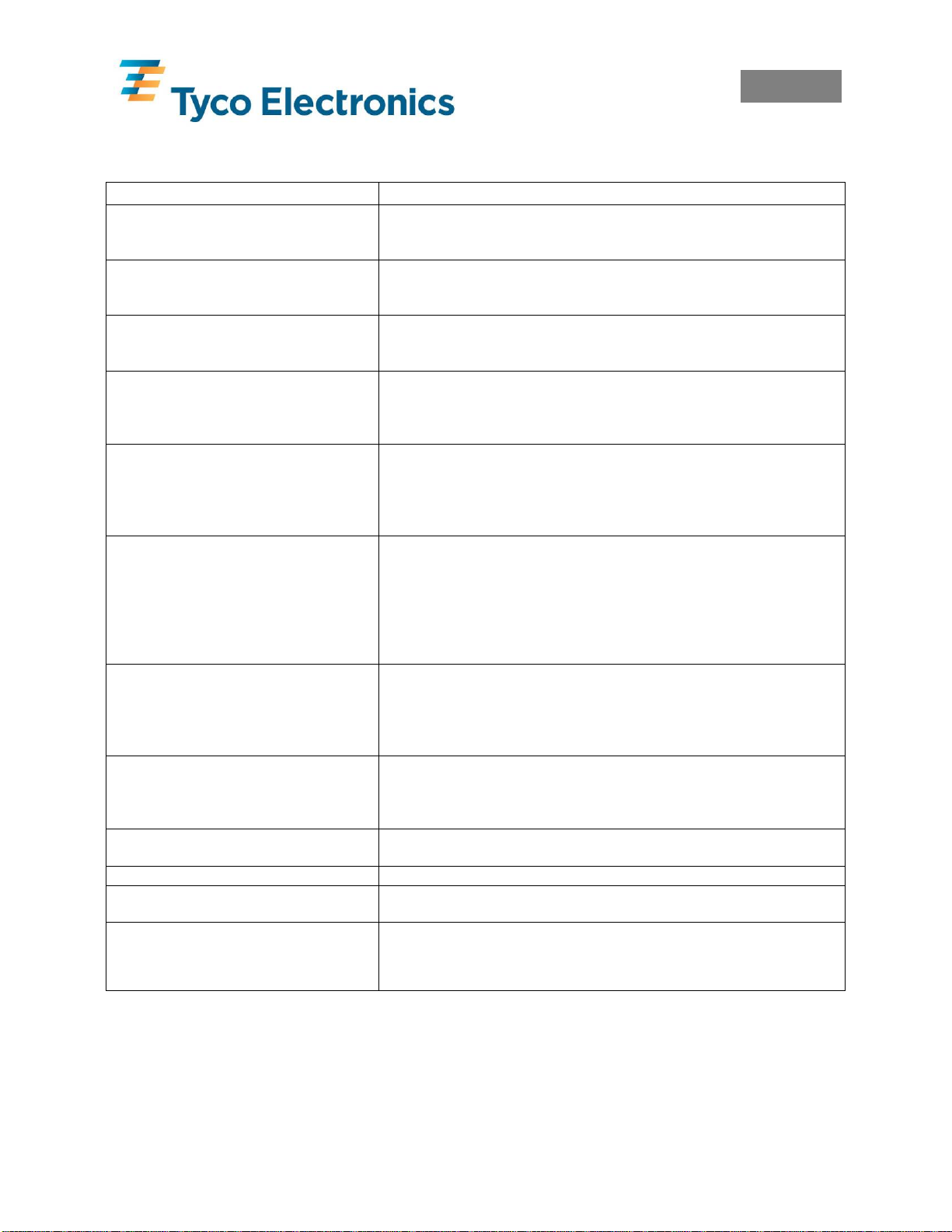
11.0 Troubleshooting
Problem Solution or Reason
No LED light after turning printer ON. 1. Check power connections from A.C. outlet to power supply to
printer.
2. Check that media or ribbon is present.
LED Orange. 1. Check the cover is closed and locked.
2. Printer has received partial data or incorrect data. Check the
software program and reboot printer.
LED Blinks Red. 1. Firmware download in process. Indicator lights red, then green.
2. Signal to begin Calibration after turning on printer. Release th e
Feed button.
LED Red. 1. Media or ribbon is out. Reload a new supply.
2. Power-up failure.
3. Printer ready to receive flash programming during firmware
download.
LED is Green but will not print. 1. Check interface cable connections from computer to printer.
2. Ensure the cover is locked closed.
3. Check that the media is loaded correctly.
4. Check that the ribbon is installed correctly and is ink side out (ink
side facing the product)
Printer appears to be working (media is
being fed out) , but nothing is printed.
Or
Printing is faded or poor quality.
Prints only partial labels or skips labels. 1. Calibrate the printer.
Printing stops and LED changes to
Orange or Red.
Wrinkles in ribbon result in missing
print
Cutter cuts through labels instear of liner 1. Check all software settings.
Cutter jammed 1. Unplug power and interface cables. Use tweezers to remove scraps
Cutter not cutting 1. Check software setting.
1. Check correct product/ribbon combination is used and loaded
correctly.
2. Check the cover is closed and locked.
3. Clean the print head with cleaning pen.
4. Adjust the print speed/darkness in software.
5. Check font types/sizes and graphics to ensure they are not too
small.
2. Check product is not getting caught whilst feeding.
3. Ensure the cover is locked closed.
4. Check software settings – especially that the Top Margin setting is
not too high.
1. Calibrate the printer.
2. Check product is not getting caught whilst feeding.
3. Check that data on label is not too large for printer memory.
4. Check all software settings.
1. Check that the ribbon is mounted straight on the take-up core.
from cutter opening.
2. Check for jams.
3. Cutter requires replacing.
For all other issues, including product or software problems, contact your local Tyco Electronics
representative.
EIL/MAN/002: REVISION 6 Date: July 2007 Page 20
Page 26
English
Appendix A
T200 Series with Cutter
The T208M-C-PRINTER and T212M-C-PRINTER have a built in media cutter. This cutter
will cut through continuous label material or the liner between the labels automatically. The
cutter should NOT be used to cut TMS marker sleeves
EIL/MAN/002: REVISION 6 Date: July 2007 Page 21
Page 27
Clearing the Media Cutter
When cutting adhesive from the labels can jam the cutter. To remove the adhesive the
following process should be carried out.
Keep the cutter dry. Never use any solutions or solvents to clean the blade.
Turn Printer OFF
Unplug all power
and interface leads.
Remove all debris
using tweezers.
Once removed plug
the printer in an test
for normal
operation
English
EIL/MAN/002: REVISION 6 Date: July 2007 Page 22
Page 28
English
Appendix B
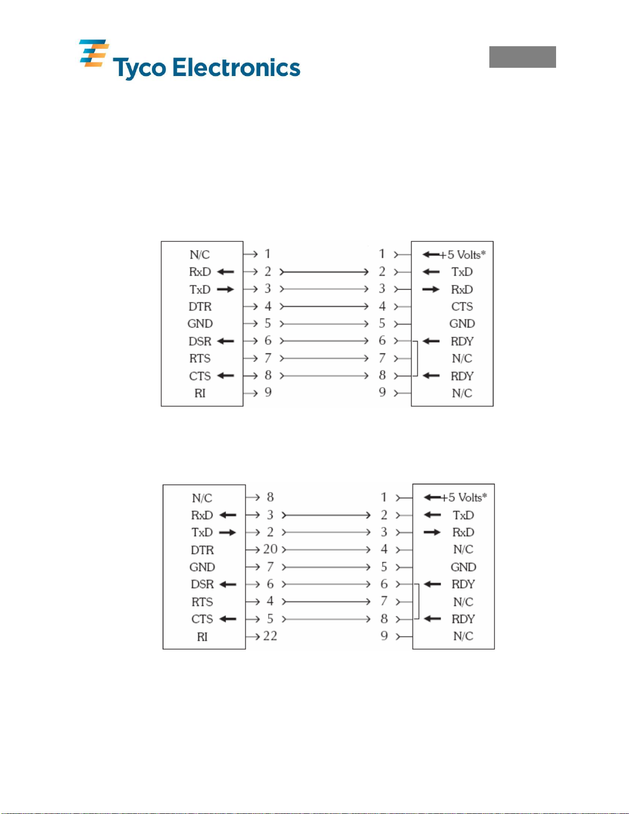
Interface Cable Wiring
Serial Interface Wiring
The figure below displays the cable wiring required to use the printers RS-232 serial interface.
* +5 volts at 150mA for external device (e.g. KDU or scanner)
DB-9
Pin #
Female DB9 to Male DB-9
DB-9
Pin #
Female DB-25 to Male DB-9
DB-9
Pin #
DB-9
Pin #
EIL/MAN/002: REVISION 6 Date: July 2007 Page 23
Page 29
English
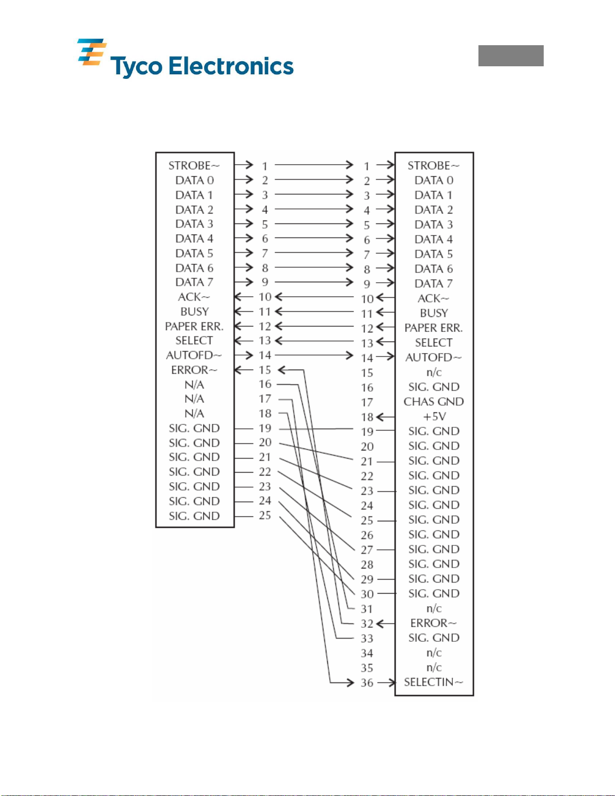
Parallel Interface Wiring
The figure below displays the cable wiring required to use the printers Centronics parallel
interface.
DB-25
Pin #
Male DB-25 to Male Centronics Cable
Centronics
Pin #
+5 Volts at 300mA for external device (e.g. KDU or scanner)
EIL/MAN/002: REVISION 6 Date: July 2007 Page 24
Page 30
English
USB (Universal Serial Bus) Interface Wiring
The table below provides the contact terminating assignments by number and electrical value
for the cable connectors.
Contact Number Signal Name Typical Wiring Assignment
1 VBUS Red
2 D- White
3 D+ Green
4 GND Black
Shell Shield Drain Wire
You can refer to the Universal Serial Bus Specification for details regarding this interface.
EIL/MAN/002: REVISION 6 Date: July 2007 Page 25
Page 31

Francàis
Francàis
IMPRIMANTE À TRANSFERT THERMIQUE
SÉRIE T200
GUIDE DE L’UTILISATEUR DU SYSTÈME
(T208M-PRINTER, T208M-C-PRINTER, T212M-PRINTER et T212M-C-PRINTER)
EIL/MAN/002: REVISION 6 Date: July 2007 Page 26
Page 32

Francàis
Avant-propos
Ce guide contient les instructions d’installation et le mode d’emploi des imprimantes T208MPRINTER(E63660-000), T208M-C-PRINTER (D82271-000), T212M-PRINTER (E23401-000)
et T212M-C-PRINTER (A53989-000), fabriquées pour Tyco Electronics.
Avis de copyright
Ce document contient de l’information propriété de Tyco Electronics. Tyco Electronics en
détient les droits d’auteur. Toute reproduction totale ou partielle sans autorisation écrite de Tyco
Electronics est interdite. Nous avons fait tous les efforts possibles pour que l’information
figurant dans ce guide soit actualisée et exacte à la date de sa publication mais ne pouvons
garantir que ce document ne contienne aucune erreur ni que toutes les spécifications soient
rigoureusement exactes. Tyco Electronics se réserve le droit d’effectuer à tout moment des
modifications dans le but d’améliorer le produit.
Marques de commerce
T208M et T212M sont des marques de services de Tyco Electronics. Windows et MS-DOS sont
des marques déposées de Microsoft Corp. Toutes les autres marques sont des marques de
commerce ou des marques déposées de leurs titulaires respectifs.
Imprimantes thermiques T208M-PRINTER, T208M-C-PRINTER, T212M-PRINTER et T212M-CPRINTER
Directive du Conseil européen Conformité aux normes
89/336/CEE Directive CEM
Directive CEM EN 55024 1988
92/31/CEE Directive CEM EN 61000-3-2 Émissions d’harmoniques
92/31/CEE Directive CEM EN 61000-3-3 Variations de tension
CB Scheme
FCC – Déclaration de conformité
Modèles : les modèles T208M-PRINTER, T208M-C-PRINTER, T212MPRINTER et T212M-C-PRINTER sont conformes aux spécifications
suivantes : Partie 15, Sous-partie B, Articles 15.107(a) et 15.109(a), appareils
numériques de la Classe B, des règles de la FCC.
Information complémentaire :
Cet appareil est conforme à la partie 15 des règles de la FCC. Son fonctionnement doit remplir les deux conditions
suivantes : (1) Cet appareil ne doit pas causer d’interférences dangereuses et (2) cet appareil doit accepter toute
interférence reçue, y compris les interférences pouvant causer un fonctionnement indésirable.
Conformité à la norme canadienne :
Cet appareil numérique de la classe B est conforme à la norme NMB-003 du Canada.
EN 55022-B
1988
EN 60950 1991
A1, A2, A3, A4
Contrôle des émissions de RF
Immunité contre les
perturbations
électromagnétiques
Sécurité
EIL/MAN/002: REVISION 6 Date: July 2007 Page 27
Page 33

Francàis
Information importante !
Une utilisation impropre de cet appareil peut causer des blessures. Il est recommandé de
former les opérateurs à sa correcte utilisation et de lire ce guide avant d’utiliser l’appareil.
La maintenance ne doit être effectuée que par du personnel qualifié et formé.
Mise en garde contre les risques d’électrocution
L’imprimante et son adaptateur d’alimentation électrique ne doivent jamais être utilisés à
un endroit où l’une ou l’autre puissent prendre l’humidité, au risque de causer des
blessures.
Mise en garde relative aux supports et aux rubans
Toujours utiliser des produits et des rubans homologués de bonne qualité. Si vous
utilisez des étiquettes sur dorsal adhésif qui ne SONT PAS bien à plat sur la doublure
dorsale, les bords exposés risquent de coller aux guides d’étiquettes et aux rouleaux à
l’intérieur de l’imprimante, ce qui décollerait l’étiquette de la doublure et entraînerait un
bourrage dans l’imprimante. L’utilisation d’un ruban non homologué risque
d’endommager irrémédiablement la tête d’impression, si son enroulement ne correspond
pas à cette imprimante ou s’il contient des produits chimiques corrosifs pour la tête
d’impression. Les fournitures homologuées peuvent être commandées chez votre
revendeur.
Conseil de chargement
Si les étiquettes ou le ruban se terminent pendant l’impression, N’ÉTEIGNEZ PAS
l’interrupteur d’alimentation (0) pendant que vous rechargez l’appareil sous peine de
perdre des données. L’imprimante redémarre automatiquement après le chargement de
nouvelles étiquettes ou d’un nouveau rouleau de ruban.
Électricité statique
La décharge d’électricité statique s’accumulant sur le corps humain ou sur d’autres
surfaces peut endommager ou détruire la tête d’impression ou les composants
électroniques utilisés dans cet appareil. NE TOUCHEZ PAS la tête d’impression ni les
composants électroniques placés sous le couvercle supérieur.
Impression thermique
La tête d’impression chauffe pendant l’impression. Pour la protéger et pour vous
protéger contre les blessures, évitez de toucher la tête d’impression. N’utilisez que le
stylo nettoyant ou une lingette imprégnée d’alcool isopropylique pour en effectuer
l’entretien.
Stockage de produits et de rubans
Tous les produits et rubans doivent être conservés dans une zone propre et non polluée,
sans poussière, graisse ni condensation. Leur stockage dans d’autres conditions peut
nuire à la qualité et la durabilité de l’image. Les conditions de stockage et la date de
péremption sont indiquées sur chaque conteneur de produits. Pour plus d’informations,
veuillez contacter Tyco Electronics.
EIL/MAN/002: REVISION 6 Date: July 2007 Page 28
Page 34

Francàis
1.0 Installation de l’imprimante
1.1 Déballage de l’imprimante
Déballez l’imprimante et conservez l’emballage pour de futurs déplacements. Au cas,
improbable, où l’imprimante ne serait pas en parfait état à son arrivée, veuillez contacter votre
représentant Tyco Electronics ou le transitaire.
Les éléments suivants devraient être livrés avec l’imprimante :
• Trois conducteurs d’alimentation : anglais, européen, américain.
• Câble de communication en parallèle.
• Adaptateur d’alimentation électrique.
• Rouleau en carton vide (pour ré-enroulement du ruban).
• Stylo nettoyant de tête d’impression.
• CD-ROM de Tyco Electronics contenant :
o Une copie électronique de ce Guide de l’utilisateur.
o Les pilotes d’imprimante pour Windows 95, 98, ME, NT4, 2000 et XP.
o Un téléchargeur de polices.
o Un téléchargeur de micrologiciels – à n’utiliser que sur indication de Tyco
Electronics.
o Un logiciel de démonstration WinTotal.
o Un logiciel de démonstration PrintEasy.
• L’échelle de contraste d’impression de Tyco Electronics.
EIL/MAN/002: REVISION 6 Date: July 2007 Page 29
Page 35

1.2 Vue d’ensemble de l’imprimante
Francàis
Capteur de ruban
Mandrin d’alimentation
de ruban
Mandrin de ré-enrouleur
de ruban
Engrenage de réenrouleur de ruban
’
Verrou du couvercle
supérieur
Porte-rouleau de
support
Capteur de support
EIL/MAN/002: REVISION 6 Date: July 2007 Page 30
Réglage des guides
Guides du support
Page 36

1.3 Branchement de l’adaptateur d’alimentation électrique de l’imprimante
Éteignez l’appareil
Vérifiez la tension
Branchez
l’adaptateur
d’alimentation
électrique
Branchez le cordon
électrique
Branchez le cordon
électrique dans une
prise CA appropriée
Francàis
EIL/MAN/002: REVISION 6 Date: July 2007 Page 31
Page 37

1.4 Connexion du câble d’interface
Éteignez
l’appareil
Port parallèle
Port série
Port USB
(bus série
universel)
Francàis
EIL/MAN/002: REVISION 6 Date: July 2007 Page 32
Page 38

Francàis
2.0 Choix du ruban
La qualité et la durabilité des impressions avec les produits Identification de Tyco Electronics
ne sont garanties que si le ruban de transfert thermique adéquat est utilisé avec chacun des
produits. Veuillez consulter la page « Printer/material/ribbon compatibility cross reference »
(Références croisées de compatibilité imprimante/matériau/ruban) sur le site
www.tycoident.com ou bien contacter Tyco Electronics.
3.0 Chargement du ruban
1. Ouvrez le couvercle.
2. Tirez sur la languette adhésive du
ruban.
3. Insérez le ruban dans le chariot.
5. Alignez les encoches avec les rayons
du mandrin.
7. Alignez les encoches sur les rayons du
mandrin.
4. Enfoncez le rouleau dans le mandrin.
6. Enfoncez le rouleau ré-enrouleur dans
le mandrin.
8. Fixez le ruban sur le rouleau ré-
enrouleur à l’aide de la languette
adhésive des rubans neufs ou avec du
ruban adhésif.
EIL/MAN/002: REVISION 6 Date: July 2007 Page 33
Page 39

Francàis
3.1 Insertion d’un ruban neuf
Si le ruban se termine en cours d’impression, le voyant s’allume en orange et l’imprimante
s’arrête. Sans éteindre l’imprimante, ouvrez le couvercle supérieur. Coupez le ruban usagé pour
pouvoir enlever les deux rouleaux. Chargez le ruban neuf comme décrit au paragraphe 3.0,
Chargement du ruban. Refermez le couvercle supérieur et appuyez sur le bouton d’alimentation
pour reprendre l’impression.
3.2 Retrait d’un ruban partiellement usagé
Pour enlever un ruban partiellement usagé, découpez la partie usagée sur le rouleau réenrouleur. Retirez le rouleau ré-enrouleur. Retirez tout le ruban usagé du rouleau ré-enrouleur
et conservez le rouleau vide pour une future réutilisation. Retirez le rouleau d’alimentation et
conservez-le dans les conditions de stockage des rubans.
Coupez la partie
usagée du ruban
Poussez sur le
rouleau
d’alimentation pour
le sortir
Remarque importante : Après avoir complètement utilisé le ruban, il faut soit remplacer le
rouleau ré-enrouleur par un rouleau en carton vide, soit retirer le ruban usagé du rouleau réenrouleur en carton. Si le ruban usagé s’accumule sur le rouleau ré-enrouleur en carton, il risque
de frotter contre le ruban neuf et de bloquer.
EIL/MAN/002: REVISION 6 Date: July 2007 Page 34
Page 40

4.0 Chargement du produit
Ouvrez le couvercle.
Séparez les guides.
Francàis
EIL/MAN/002: REVISION 6 Date: July 2007 Page 35
Page 41

Francàis
4.1 Chargement des manchons de marquage TMS
Les manchons de marquage TMS peuvent être chargés de l’intérieur ou de l’extérieur. Les deux
méthodes exigent que le porte-rouleau de support soit maintenu ouvert et que la vis de blocage
soit serrée à l’aide d’un tournevis.
4.1.1 Chargement intérieur des manchons de marquage TMS
Retirez l’emballage et le grand rouleau en carton ; placez le produit libre dans la baie de support
de l’imprimante. Cette méthode est possible avec les manchons de marquage TMS et avec
certaines étiquettes auto-collantes enroulées sur de grands rouleaux en carton.
4.1.2 Chargement extérieur des manchons de marquage TMS
Le produit peut être inséré dans l’imprimante au moyen de la fente qui se trouve à l’arrière de
l’imprimante. Cette méthode convient si l’on souhaite laisser les manchons de marquage TMS
dans la boîte en carton dans laquelle ils sont livrés.
EIL/MAN/002: REVISION 6 Date: July 2007 Page 36
Page 42

Francàis
4.2 Chargement d’étiquettes
Les étiquettes peuvent être chargées par l’intérieur ou par l’extérieur.
4.2.1 Chargement intérieur d’étiquettes
Les étiquettes fournies sur de petits rouleaux en carton peuvent être maintenues en place par le
porte-rouleau de support à ressort.
Les étiquettes ne s’adaptant pas au porte-rouleau peuvent être ôtées de leur rouleau et placées
librement dans la baie de support de l’imprimante. Si l’on choisit cette méthode, le porterouleau de support doit être bloqué sur la position d’ouverture ; voir le chapitre 4.1 Chargement
des manchons de marquage TMS.
4.2.2 Chargement extérieur d’étiquettes
Les étiquettes peuvent être insérées dans l’imprimante au moyen de la fente qui se trouve à
l’arrière de l’imprimante. Cette méthode est applicable si les étiquettes ne rentrent pas dans le
porte-rouleau intérieur de support. Un porte-support adapté doit être utilisé. Veuillez contacter
Tyco Electronics pour plus de détails.
EIL/MAN/002: REVISION 6 Date: July 2007 Page 37
Page 43

Francàis
4.3 Chargement du produit (suite)
Le(la) premier(ère) manchon de marquage/étiquette doivent être placés sur le rouleau presseur
en caoutchouc noir. Une fois chargé(e), refermer les guides-support pour qu’ils agrippent
légèrement le produit.
Dégagez le couvercle
Refermez le couvercle
EIL/MAN/002: REVISION 6 Date: July 2007 Page 38
Page 44

Francàis
5.0 Calibrage
Quand vous changez de type de produit ou que vous en chargez un nouveau, l’imprimante doit
être calibrée.
Après avoir correctement installé le produit et le ruban, procédez comme suit :
1. Éteignez l’appareil.
3. Tout en maintenant la pression sur le
bouton d’alimentation, allumez
l’appareil.
5. L’imprimante fait avancer le support et
imprime un résumé d’état.
2. Appuyez sur le bouton d’alimentation.
4. Attendez que le voyant clignote 3 fois
en rouge et relâchez le bouton
d’alimentation.
6. Appuyez sur le bouton d’alimentation
pour activer le fonctionnement normal.
Remarque : L’imprimante est sur le mode image
de diagnostic. La première ligne imprimée sur le
papier pendant le calibrage correspond à la version
du micrologiciel.
7. À chaque fois que vous appuyez sur le
bouton d’alimentation, le papier doit
avancer d’un manchon de
marquage/étiquette.
EIL/MAN/002: REVISION 6 Date: July 2007 Page 39
Remarque :
Si l’imprimante s’alimente en continu ou fait
avancer plus d’un manchon de marquage ou
d’une étiquette à la fois, ou si le voyant reste
orange ou rouge, reportez-vous au chapitre 5.1
Alignement de calibrage et au chapitre 11.0
Dépannage, puis répétez la procédure de
calibrage.
Page 45

Francàis
5.1 Alignement de calibrage
Le calibrage peut être difficile à réaliser avec certains produits généralement parce que le délai
de retard du capteur est dépassé avant qu’il n’ait pu reconnaître le contraste entre l’étiquette et le
dorsal du support.
La réduction du temps dont dispose le capteur pour détecter la différence entre les étiquettes et
le matériau du dorsal permettra de calibrer correctement le capteur.
5.1.1 Alignement des étiquettes
Placez une étiquette sous le capteur de la T200 de sorte que moins de 5 mm environ d’étiquette
ne se déplace avant que le matériau du dorsal ne soit détecté par le capteur.
Environ 5 mm
5.1.2 Alignement d’étiquettes à perforations pour capteur
Placez une étiquette sous le capteur de la T200 de sorte que moins de 5 mm environ d’étiquette
ne se déplace avant que la perforation pour capteur ne soit détectée par le capteur.
REMARQUE : Les étiquettes ne seront calibrées que si elles passent directement sous le
capteur. Les produits dont les étiquettes ne se trouvent pas directement sous le capteur ne seront
pas calibrés. Une perforation pour capteur ou une marque noire sont nécessaires pour calibrer
ces produits. Si vous utilisez une marque noire, le réglage par défaut du capteur doit être
modifié dans l’imprimante. Reportez-vous au chapitre 6.0 Changement du type de capteur.
Capteur
5 mm environ
EIL/MAN/002: REVISION 6 Date: July 2007 Page 40
Page 46

Francàis
6.0 Changement du type de capteur
Le capteur par défaut de la T200 est un capteur transmissif (bobine) qui devrait fonctionner avec
tous les produits TMS et les étiquettes standard. Si le capteur Réflectif (marque noire) ou le
mode Continu sont requis, procédez comme indiqué ci-après.
6.1 Capteur réflectif (marque noire)
Pour activer le capteur Réflectif (marque noire), imprimez une étiquette avec le capteur réglé sur
« Réflectif (marque noire) » dans « Édition d’étiquettes avancée » de WinTotal ou dans « Pilote
d’imprimante Windows » de PrintEasy. Après l’impression d’une étiquette avec ces paramètres,
le voyant s’allume en rouge. Il faut alors calibrer l’imprimante sur le produit Réflectif (marque
noire).
6.2 Mode de détection continue
Pour imprimer des produits continus, l’imprimante doit être réglée sur le mode continu. Pour ce
faire, imprimez une étiquette avec le capteur réglé sur « Continu » dans « Édition d’étiquettes
avancée » de WinTotal ou dans « Pilote d’imprimante Windows » de PrintEasy. Après
l’impression d’une étiquette avec ces paramètres, le voyant s’allume en rouge. Il faut alors
calibrer l’imprimante sur le produit continu.
6.3 Capteur transmissif
Pour revenir au capteur Transmissif (bobine), imprimez une étiquette avec le capteur réglé sur
« Transmissif (bobine) » dans « Édition d’étiquettes avancée » de WinTotal ou dans « Pilote
d’imprimante Windows » de PrintEasy. Après l’impression d’une étiquette avec ces paramètres,
le voyant s’allume en rouge. Il faut alors calibrer l’imprimante sur le produit transmissif
(bobine).
Remarque : Le procédé de calibrage est le même pour tous les modes de détection et est décrit
au chapitre 5.0 Calibrage.
7.0 Versions du micrologiciel de l’imprimante
La version correcte du micrologiciel est pré-chargée dans les imprimantes :
T208M et T208M-C - version 4.51 ou supérieure du micrologiciel.
T212M et T212M-C - version 4.51 ou supérieure du micrologiciel.
Ne modifiez et n’actualisez pas la version du micrologiciel sans auparavant vérifier auprès de
Tyco Electronics. Toutes les versions du micrologiciel ne permettent pas une impression
réussie des produits d’identification de Tyco Electronics.
Vérifiez la version du micrologiciel en faisant un calibrage de l’imprimante (voir chapitre 5.0
Calibrage).
EIL/MAN/002: REVISION 6 Date: July 2007 Page 41
Page 47

Francàis
8.0 Logiciel
Le logiciel conseillé pour imprimer avec une T200 est soit WinTotal pour les manchons TMS et
le format standard d’étiquettes, soit PrintEasy pour les étiquettes. Des versions de démonstration
de ces deux logiciels sont fournies dans le CD.
WinTotal comporte des pilotes d’imprimante intégrés.
PrintEasy utilise les pilotes d’imprimante Windows qui peuvent être automatiquement installés
à partir du CD. Ces pilotes fonctionnent avec Windows 95, 98, ME, NT4, 2000 et XP.
Ces deux logiciels permettent de contrôler tous les aspects importants de l’imprimante, y
compris la vitesse et le niveau de luminosité. La plupart des produits sont correctement
imprimés avec les paramètres par défaut de l’un ou l’autre des logiciels. L’augmentation du
niveau de luminosité améliore normalement la qualité de l’impression.
Remarque : Pour plus de détails, veuillez consulter la documentation des logiciels ou contacter
votre représentant local Tyco Electronics.
9.0 Qualité d’impression
Pour garantir l’obtention d’une bonne qualité d’impression, le produit imprimé doit avoir une
valeur de contraste d’au moins 8 (et de préférence 9-10) sur l’échelle de contraste d’impression
de Tyco Electronics.
EIL/MAN/002: REVISION 6 Date: July 2007 Page 42
Page 48

Francàis
10.0 Entretien
10.1 Nettoyage de la tête d’impression
Il est recommandé de nettoyer la tête d’impression après consommation d’un rouleau de ruban.
Utilisez pour ce faire le stylo nettoyant qui vous est livré avec l’imprimante ou tout produit
habituel de nettoyage de tête d’impression d’imprimantes à transfert thermique (par exemple,
une lingette imprégnée d’alcool isopropylique).
Éteignez
l’imprimante
Frottez le stylo
nettoyant sur la
surface foncée de la
tête d’impression
Ne nettoyez pas le
rouleau de la platine
avec le stylo
nettoyant
EIL/MAN/002: REVISION 6 Date: July 2007 Page 43
Page 49

Francàis
10.2 Nettoyage du rouleau de la platine
Avec le temps, la poussière d’adhésif encrasse la platine qui doit alors être nettoyée. Utilisez
pour ce faire un chiffon propre non pelucheux légèrement humidifié avec de l’alcool
isopropylique.
Éteignez
l’imprimante.
Débranchez tous les
câbles
d’alimentation et
d’interface.
Essuyez doucement
le dessus de la
platine
Faites avancer la
platine d’un sixième
(1/6) de tour
Répétez les
opérations jusqu’à
ce que la platine soit
propre
Remarque : Laissez la platine sécher pendant au moins une minute avant de charger le support.
EIL/MAN/002: REVISION 6 Date: July 2007 Page 44
Page 50

Francàis
11.0 Dépannage
Problème Solution ou cause
Le voyant ne s’allume pas après
avoir allumé l’imprimante.
Voyant orange. 1. Vérifiez que le couvercle est fermé et verrouillé.
Le voyant clignote en rouge. 1. Le téléchargement du micrologiciel est en cours. Le voyant
Voyant rouge. 1. Fin du support ou du ruban. Réalimentez.
Le voyant est vert mais
l’impression ne se fait pas.
L’imprimante semble fonctionner
(le support en sort) mais rien ne
s’imprime.
Ou
L’impression est trop claire ou de
mauvaise qualité.
N’imprime que partiellement les
étiquettes ou en saute certaines.
L’imprimante s’arrête et le voyant
passe à l’orange ou au rouge.
Des plis du ruban provoquent des
manques dans l’impression.
Le massicot coupe les étiquettes au
lieu de la doublure.
Bourrage dans le massicot. 2. Débranchez les câbles électriques et d’interface. Enlevez les
Le massicot ne coupe pas. 1. Vérifiez les paramètres du logiciel.
1. Vérifiez les branchements électriques entre la prise CA,
l’adaptateur et l’imprimante.
2. Vérifiez que le support ou le ruban sont présents.
2. L’imprimante a reçu des données partielles ou erronées. Vérifiez le
programme du logiciel et réinitialisez l’imprimante.
s’allume en rouge puis en vert.
2. Signal pour commencer le calibrage après avoir allumé
l’imprimante. Relâchez le bouton d’alimentation.
2. Panne d’alimentation.
3. L’imprimante est prête à recevoir une programmation Flash
pendant le téléchargement du micrologiciel.
1. Vérifiez les connexions du câble d’interface entre l’imprimante et
l’ordinateur.
2. Vérifiez que le couvercle est fermé et verrouillé.
3. Vérifiez que le support est correctement chargé.
4. Vérifiez que le ruban est correctement installé et que le côté encré
est dirigé vers l’extérieur (face au produit).
1. Vérifiez que la combinaison produit/ruban utilisée est co rrecte et
que le chargement a été correctement effectué.
2. Vérifiez que le couvercle est fermé et verrouillé.
3. Nettoyez la tête d’impression avec le stylo nettoyant.
4. Réglez la vitesse/luminosité d’impression dans le logiciel.
5. Vérifiez que les types/tailles de polices et les graphiques ne sont pas
trop petits.
1. Calibrez l’imprimante.
2. Vérifiez que le produit ne reste pas coincé pendant l’alimentation.
3. Vérifiez que le couvercle est fermé et verrouillé.
4. Vérifiez les paramètres du logiciel – en particulier que le réglage de
la marge supérieure n’est pas trop élevé.
1. Calibrez l’imprimante.
2. Vérifiez que le produit ne reste pas coincé pendant l’alimentation.
3. Vérifiez que les données de l’étiquette ne sont pas trop lourdes pour
la mémoire de l’imprimante.
4. Vérifiez tous les paramètres du logiciel.
1. Vérifiez que le ruban s’enroule bien droit sur le rouleau ré-
enrouleur.
1. Vérifiez tous les paramètres du logiciel.
morceaux de l’ouverture du massicot à l’aide d’une pince.
2. Recherchez des bourrages.
3. Le massicot doit être remplacé.
Pour tout autre problème, y compris les problèmes de produit ou de logiciel, veuillez contacter
votre représentant Tyco Electronics.
EIL/MAN/002: REVISION 6 Date: July 2007 Page 45
Page 51

Francàis
Annexe A
Série T200 avec massicot
Les imprimantes T208M-C et T212M-C sont équipées d’un massicot de support intégré. Ce
massicot coupe le matériau continu des étiquettes ou la doublure entre les étiquettes de manière
automatique. Le massicot NE DOIT PAS servir à couper les manchons de marquage TMS.
EIL/MAN/002: REVISION 6 Date: July 2007 Page 46
Page 52

Francàis
Déblocage du massicot de support
L’adhésif des étiquettes peut provoquer un bourrage dans le massicot. Pour enlever l’adhésif,
procédez comme indiqué ci-dessous.
Le massicot doit rester sec. N’utilisez aucune solution ni solvant pour nettoyer la lame.
Éteignez
l’imprimante.
Débranchez tous les
câbles
d’alimentation et
d’interface.
Retirez tous les
débris avec une
pince
Rebranchez
l’imprimante et
faites un test de
fonctionnement
EIL/MAN/002: REVISION 6 Date: July 2007 Page 47
Page 53

Francàis
Annexe B
Câblage du câble d’interface
Câbles d’interface en série
La figure ci-dessous montre le câblage requis pour utiliser l’interface d’imprimantes en série
RS-232.
* +5 volts à 150 mA pour appareil externe (par ex., KDU ou scanner)
DB-9
Fiche #
DB9 femelle à DB-9 mâle
DB-9
Fiche #
DB-25 femelle à DB-9 mâle
DB-9
Fiche #
DB-9
Fiche #
EIL/MAN/002: REVISION 6 Date: July 2007 Page 48
Page 54

Francàis
Câblage d’interface en parallèle
La figure ci-dessous montre le câblage requis pour utiliser l’interface d’imprimantes en parallèle
Centronics.
+5 volts à 300 mA pour appareil externe (par ex., KDU ou scanner)
DB-25
Fiche
Male DB-25 to Male Centronics Cable
Centronic
s
EIL/MAN/002: REVISION 6 Date: July 2007 Page 49
Page 55

Francàis
Câblage d’interface USB (bus série universel)
Le tableau ci-dessous indique les attributions de terminaisons de contacts par numéro et valeur
électrique des connecteurs de câbles.
Numéro de contact Nom du signal Attribution habituelle de
câblage
1 VBUS Rouge
2 D- Blanc
3 D+ Vert
4 TERRE Noir
Gaine Blindage Conducteur de drainage
Reportez-vous aux spécifications de l’USB pour plus de détails concernant cette interface.
EIL/MAN/002: REVISION 6 Date: July 2007 Page 50
Page 56

Deutsch
Deutsch
T200 SERIE THERMOTRANSFER-DRUCKERSYSTEM
BENUTZERHANDBUCH
(T208M-PRINTER, T208M-C-PRINTER, T212M-PRINTER und T212M-C-PRINTER)
EIL/MAN/002: REVISION 6 Date: July 2007 Page 51
Page 57

Deutsch
Vorwort
Dieses Handbuch stellt Informationen zur Aufstellung und Inbetriebnahme für die DRUCKER
T208M-PRINTER (E63660-000), T208M-C-PRINTER (D82271-000), T212M-PRINTER
(E23401-000) und T212M-C-PRINTER (A53989-000) bereit, hergestellt für Tyco Electronics.
Copyright-Hinweis
Dieses Dokument enthält Informationen, die Eigentum von Tyco Electronics sind. Dieses
Dokument und die darin enthaltenen Informationen sind für Tyco Electronics geschützt und
dürfen von niemandem weder vollständig noch in Teilen ohne schriftliche Erlaubnis von Tyco
Electronics dupliziert werden. Obwohl jede mögliche Anstrengung unternommen wurde, um die
Informationen darin auf dem Laufenden und so exakt wie möglich zum Tage der
Veröffentlichung zu halten, wird keine Garantie gegeben oder stillschweigend angenommen,
dass das Dokument fehlerfrei ist oder dass es hinsichtlich etwaiger Produktänderungen richtig
ist. Tyco Electronics behält sich das Recht vor, zu jeder Zeit Änderungen zum Zwecke der
Produktverbesserung durchzuführen.
Marken
T208M und T212M sind Handelsmarken von Tyco Electronics. Windows und MS-DOS sind
eingetragene Marken der Microsoft Corp. Alle anderen Marken sind Marken oder eingetragene
Handelsmarken der jeweiligen Firmen.
T208M-PRINTER, T208M-C-PRINTER, T212M-PRINTER und T212M-C-PRINTER Thermodrucker
EU-Richtlinien Richtlinienkonformität
89/336/EW
G
92/31/EWG
92/31/EWG
CB-Schema
FCC – Konformitätserklärung
Die Modelle T208M-PRINTER, T208M-C-PRINTER, T212M-PRINTER und
T212M-C-PRINTER stimmen mit den folgenden Spezifizierungen überein:
FCC Teil 15, Unterabteilung B, Sektion 15.107(a) und Sektion 15.109(a),
Klasse B, Digitalgeräte.
Zusätzliche Information:
Dieses Gerät stimmt mit Teil 15 der FCC-Regelungen überein. Der Betrieb unterliegt den folgenen zwei
Bedingungen: (1) Dieses Gerät darf keine schädlichen Störungen hervorrufen, und (2) dieses Gerät muss alle
Störungen vertragen, einschließlich Störungen, die einen unerwünschten Betrieb hervorrufen.
Hinweis zu Industry Canada:
Dieses Gerät stimmt mit den Anforderungen der Industry Canada ICS-003, Klasse B, überein.
EMC-
Richtlinien
EMC-
Richtlinien
EMC-
Richtlinien
EMC-
Richtlinien
EN 55022-B
1988
EN 55024 1988
EN 61000-3-2 Harmonische Emissionen
EN 61000-3-3 Spannungsschwankungen
EN 60950 1991
A1, A2, A3, A4
RF Emissionskontrolle
Schutz vor elektro-
magnetischen Störungen
Sicherheit
EIL/MAN/002: REVISION 6 Date: July 2007 Page 52
Page 58

Deutsch
Wichtige Information!
Die unkorrekte Benutzung dieses Gerätes kann Verletzungen hervorrufen. Es wird
empfohlen, dass die Benutzer im korrekten Umgang mit dem Gerät geschult werden und
sie dieses Handbuch vor dem Gebrauch lesen.
Die Wartung darf ausschließlich durch dafür geeignetes und geschultes Personal
durchgeführt werden.
Warnung vor Stromschlag:
Der Drucker und die Stromversorgung dürfen niemals in einem Bereich betrieben
werden, in dem sie Nässe ausgesetzt sein können. Dies kann die Verletzung von
Personen zur Folge haben.
Warnung zu Druckmedien und Farbband:
Benutzen Sie immer zugelassene Druckmedien und Farbbänder von hoher Qualität.
Wenn Selbstklebeetiketten benutzt werden, die NICHT flach auf dem Trägerpapier
aufliegen, können die Sticker mit ihren Ecken an den Etiketten- und Rollenführungen
innerhalb des Druckers festkleben, die Ablösung des Etiketts vom Träger hervorrufen
und so den Drucker blockieren. Der Druckkopf kann auf Dauer dadurch zerstört werden,
dass ein nicht zugelassenes Farbband benutzt wird, da es in ungeeigneter Weise
aufgerollt sein oder für den Druckkopf korrosive Chemikalien enthalten kann.
Zugelassene Produkte können von Ihrem Händler geliefert werden.
Hinweis zum Einlegen:
Falls die Etiketten oder das Farbband während des Druckes ausgehen sollten , schalten
Sie beim Einlegen NICHT den Schalter auf AUS (0), da sonst ein Datenverlust die Folge
sein kann. Der Drucker startet automatisch neu, nachdem Sie ein neues Etikett oder eine
neue Farbbandrolle eingelegt haben.
Statische Entladung:
Das Entladen statischer Energie, die sich auf der menschlichen Haut oder auf anderen
Oberflächen gebildet hat, kann den Druckkopf oder in diesem Gerät eingesetzte
elektronische Komponenten beschädigen oder zerstören. BERÜHREN SIE NICHT den
Druckkopf oder andere elektronische Komponenten unter der oberen Abdeckung.
Thermodruck:
Der Druckkopf erhitzt sich während des Druckens. Um den Druckkopf vor Schaden zu
bewahren und Verletzungen von Personen zu verhindern, vermeiden Sie eine Berührung
des Druckkopfes. Benutzen Sie nur den Reinigungsstift oder ein IPA-Tuch, um die
Wartung durchzuführen.
Lagerung von Druckmedien und Farbbändern:
Alle Druckmedien und Farbbänder müssen in einem sauberen Bereich gelagert werden,
der frei von Verschmutzung, Staub, Fett und hoher Luftfeuchtigkeit ist. Ansonsten kann
die Druckqualität und die Lebensdauer leiden. Die Lagerbedingungen und -zeit sind auf
jedem Druckmedienbehälter vermerkt. Wenden Sie sich zu weitergehenden
Informationen bitte an Tyco Electronics.
EIL/MAN/002: REVISION 6 Date: July 2007 Page 53
Page 59

Deutsch
1.0 Aufbau des Druckers
1.1 Den Drucker auspacken
Packen Sie den Drucker aus, und stellen Sie dabei sicher, dass das gesamte
Verpackungsmaterial für einen zukünftigen Transport behalten wird. Sollte der Drucker in dem
unwahrscheinlichen Fall in einem fehlerhaften Zustand sein, so wenden Sie sich bitte an Ihren
Tyco Electronics Vertreter oder an die Transportfirma.
Die folgenden Bestandteile sollten mit dem Drucker mitgeliefert werden:
• Drei Netzkabel für UK, Europa und USA.
• Paralleles Kommunikationskabel.
• Stromversorgung.
• Zusätzliche Pappehülse (für Farbbandaufnahme).
• Druckkopf-Reinigungsstift.
• Tyco Electronics CD-ROM mit folgendem Inhalt…
o Elektronisches Handbuch.
o Druckertreiber für Windows 95, 98, ME, NT4, 2000 und XP.
o Downloadprogramm für Schriften.
o Downloadprogramm für Firmware – nur zu benutzen, wenn durch Tyco
Electronics empfohlen.
o Wintotal Demo-Software.
o PrintEasy Demo-Software.
• Tyco Electronics Druckkontrast-Skala.
EIL/MAN/002: REVISION 6 Date: July 2007 Page 54
Page 60

r
g
r
1.2 Überblick über den Drucker
Deutsch
Farbband-Senso
Abreißbalken
Farbband-
Zuführungs-Rollenhalter
Farbband-
AufnehmerRollenhalte
Farbband-AufnehmerAntrieb
Druckkopf
Sperre obere
Abdeckun
Rollenhalter
Druckmedium
Druckmedium-Sensor
Einstellung Führungen
Druckmediumführung
EIL/MAN/002: REVISION 6 Date: July 2007 Page 55
Page 61

1.3 Anschluss des Druckers an die Stromversorgung
Drucker ausschalten
Prüfen der
Spannung
Strommodul
einstecken
Netzkabel
einstecken
Netzkabel
in geeignete
Steckdose
einstecken
Deutsch
SpannungsAufdruck
EIL/MAN/002: REVISION 6 Date: July 2007 Page 56
Page 62

1.4 Anschluss des Interface-Kabels
Drucker
ausschalten
Parallel
Seriell
USB
(Universal
Serial Bus)
Deutsch
EIL/MAN/002: REVISION 6 Date: July 2007 Page 57
Page 63

Deutsch
2.0 Auswahl des Farbbands
Die Druckqualität und die Lebensdauer von Tyco Electronics Identifikationsprodukten sind nur
gewährleistet, wenn das korrekte Thermotransfer-Farbband für jedes Produkt benutzt wird.
Schauen Sie bitte unter dem Titel „Printer/material/ribbon compatibility cross reference“ nach,
den Sie auf www.tycoident.com finden können, oder wenden Sie sich an Tyco Electronics.
3.0 Einlegen des Farbbands
1. Öffnen Sie die Abdeckung.
3. Führen Sie das Farbband durch die
Durchführung.
2. Ziehen Sie den Klebestreifen ab.
4. Drücken Sie die Farbbandhülse gegen
den Rollenaufnehmer.
5. Rasten Sie die Rollenöffnungen in die
Aufnehmer ein.
7. Rasten Sie die Hülsenöffnungen in die
Aufnehmer ein.
6. Drücken Sie die Leerhülse gegen den
Aufnehmer.
8. Befestigen Sie das Farbband an der
Leerhülse mit Hilfe des Klebestreifens.
EIL/MAN/002: REVISION 6 Date: July 2007 Page 58
Page 64

Deutsch
3.1 Ein neues Farbband einlegen
Falls während des Druckens das Farbband endet, leuchten die Anzeigelampen orange, und der
Drucker hält an. Lassen Sie das Gerät eingeschaltet, öffnen Sie die obere Abdeckung. Schneiden
Sie das gebrauchte Farbband durch, so dass beide Hülsen entfernt werden können. Legen Sie
das neue Farbband wie unter Abschnitt 3.0 „Einlegen des Farbbands“ beschrieben ein.
Schließen Sie die obere Abdeckung, und drücken Sie den Einzugknopf, um das Drucken
fortzusetzen.
3.2 Entfernen eines teilweise gebrauchten Farbbands
Um ein teilweise gebrauchtes Farbband zu entfernen, schneiden Sie das Farbband von der
Aufnehmerrolle ab. Entfernen Sie die Aufnehmerrolle. Entfernen Sie das gebrauchte Farbband
vollständig von der Aufnehmerhülse, und bewahren Sie die leere Hülse für zukünftigen
Gebrauch auf. Entfernen Sie die Zuführungsrolle, und bewahren Sie diese gemäß den
Lagerbedingungen für Farbbänder.
Schneiden Sie das
gebrauchte
Farbband von der
Zuführungsrolle ab
Ziehen Sie die
Zuführungsrolle
heraus
Wichtiger Hinweis: Wenn ein Farbband vollständig aufgebraucht ist, muss die Aufnehmerrolle
durch eine leere Pappehülse ersetzt werden, oder das verbrauchte Farbband muss von der
Aufnehmerhülse entfernt werden. Lässt man das verbrauchte Farbband auf der Aufnehmerrolle,
kann ansonsten das verbrauchte Farbband gegen das neue Farbband reiben und eine Stauung
hervorrufen.
EIL/MAN/002: REVISION 6 Date: July 2007 Page 59
Page 65

4.0 Einlegen von Druckmedien
Öffnen Sie die Abdeckung
Öffnen Sie die Führungen
Deutsch
EIL/MAN/002: REVISION 6 Date: July 2007 Page 60
Page 66

Deutsch
4.1 Einlegen der TMS Markierungsbanderolen
TMS Markierungsbanderolen können sowohl intern als auch extern eingezogen werden. In
beiden Fällen ist es erforderlich, dass die Druckmedienrollenhalter offen sind und die
Feststellschrauben mit einem Schraubenzieher angezogen werden.
4.1.1 TMS Markierungsbanderolen: interner Einzug
Entfernen Sie die Verpackung und die große Papphülse, und platzieren Sie das Druckmedium
lose in den Druckmediumschacht des Druckers. Dieser ist für TMS Markierungsbanderolen und
einige selbstklebende Etikettendruckmedien mit großen Papphülsen geeignet.
4.1.2 TMS Markierungsbanderolen: externer Einzug
Das Druckmedium kann in den Drucker über den Einzugsschacht auf der Rückseite des
Druckers zugeführt werden. Dies empfiehlt sich, wenn die TMS Markierungsbanderolen in dem
Pappkarton, in dem sie geliefert wurden, verbleiben sollen.
EIL/MAN/002: REVISION 6 Date: July 2007 Page 61
Page 67

4.2 Einlegen von Etiketten
Etiketten können sowohl intern als auch extern eingezogen werden.
4.2.1 Etiketten: interner Einzug
Etiketten, die auf kleinen Papphülsen geliefert werden, können durch die federbelasteten
Druckmediumrollenhalter an ihrem Platz gehalten werden.
Deutsch
Etiketten, die nicht in die Druckmediumrollenhalter passen, können von ihrer Hülse befreit und
lose in den Druckmediumschacht des Druckers platziert werden. Die Druckmediumrollenhalter
müssen dazu frei sein, siehe auch Abschnitt 4.1 Einlegen von TMS Markierungsbanderolen.
4.2.2 Etiketten: externer Einzug
Etiketten können in den Drucker über den Einzugsschacht auf der Rückseite des Druckers
eingezogen werden. Dies ist angebracht, wenn die Etiketten nicht in den internen
Druckmediumrollenhalter passen. Ein entsprechender Druckmediumhalter sollte benutzt
werden. Wenden Sie sich bitte wegen weiterer Einzelheiten an Tyco Electronics.
EIL/MAN/002: REVISION 6 Date: July 2007 Page 62
Page 68

Deutsch
4.3 Einlegen von Druckmedien Fortsetzung
Die/das erste Markierungsbanderole/Etikett muss auf der schwarzen Gummiandruckwalze
positioniert werden. Schließen Sie die Druckmediumführungen, damit das Druckmedium leicht
gegriffen werden kann, wenn es eingelegt ist.
Lösen Sie die Abdeckung
Schließen Sie die Abdeckung
EIL/MAN/002: REVISION 6 Date: July 2007 Page 63
Page 69

Deutsch
5.0 Kalibrierung
Der Drucker muss kalibriert werden, wenn Sie ein neues oder anderes Druckmedium einlegen.
Nachdem das Druckmedium und das Farbband korrekt installiert sind, muss folgende
Vorgehensweise durchgeführt werden.
1. Drucker ausschalten.
3. Halten Sie den Zufuhrknopf gedrückt, und
schalten Sie den Drucker ein.
2. Halten Sie den Zufuhrknopf gedrückt.
4. Wenn die LED dreimal rot aufleuchtet,
lassen Sie den Zufuhrknopf los.
5. Der Drucker gibt eine Zusammenfassung
des Druckmediums und des Druck-Status
aus.
Hinweis: Der Drucker ist im sog. Prüfausdruckmodus.
Die erste Zeile während des Kalibrierungs-Modus zeigt
die Firmware-Version an.
7. Jeder Druck auf den Zufuhrknopf sollte nun
eine Markierungsbanderole bzw. ein Etikett
vorrücken.
6. Drücken Sie den Zufuhrknopf, um den
Normalbetrieb zu starten.
Hinweis:
Sollte der Drucker unaufhörlich oder mehr als
eine Markierungsbanderole bzw. ein Etikett
zugleich vorrücken, oder die LED bleibt
orange oder rot, dann schauen Sie bitte unter
Abschnitt 5.1 Ausrichtung zur Kalibrierung
und 11.0 Fehlerbehebung nach, und
wiederholen Sie den Kalibrierungsprozess.
EIL/MAN/002: REVISION 6 Date: July 2007 Page 64
Page 70

Deutsch
5.1 Ausrichtung zur Kalibrierung
Die Kalibrierung kann bei einigen Druckmedien nur schwierig durchzuführen sein. Dies ist
normalerweise wegen der Rückstellung des Sensors der Fall, bevor der Kontrast von Etikett und
Trägermaterial durch den Druckersensor erkannt wird.
Indem man die Zeit reduziert, die der Sensor benötigt, um die Unterschiede zwischen dem
Etikett und dem Trägermaterial aufzunehmen, kann eine erfolgreiche Sensorkalibrierung
durchgeführt werden.
5.1.1 Ausrichtung der Etiketten
Positionieren Sie ein Etikett unter den T200 Sensor mit weniger als ca. 5 mm Etikettentransport,
bevor das Trägermaterial von dem Sensor aufgenommen wird.
ca. 5 mm
5.1.2 Etiketten mit Sensorlochausrichtung
Positionieren Sie ein Etikett unter den T200 Sensor mit weniger als ca. 5 mm
Druckmediumtransport, bevor das Sensorloch von dem Sensor aufgenommen wird.
ca. 5 mm
HINWEIS: Etiketten lassen sich nur kalibrieren, wenn sie direkt unter dem Sensor durchgeführt
werden. Druckmedien, die kein Etikett direkt unter dem Sensor haben, können nicht kalibriert
werden. Um diese Medien kalibrieren zu können, ist ein Sensorloch oder eine schwarze
Markierung erforderlich. Wenn die schwarze Markierung benutzt werden soll, so muss die
EIL/MAN/002: REVISION 6 Date: July 2007 Page 65
Page 71

Deutsch
Grundeinstellung für den Sensor im Drucker geändert werden. Siehe auch Abschnitt 6.0
Wechsel des Sensortyps.
6.0 Wechsel des Sensortyps
Der vorab installierte Sensor für die T200 ist der Sensor für lichtdurchlässige Druckmedien
(Bahn). Dieser sollte für alle TMS-Produkte und Standardetiketten ausreichend sein. Falls der
Reflektionssensor (schwarze Markierung) benötigt wird oder der Endlosmodus erforderlich ist,
so müssen die entsprechenden Maßnahmen durchgeführt werden.
6.1 Reflektionssensor (schwarze Markierung)
Um den Reflektionssensor (schwarze Markierung) zu aktivieren, muss ein Etikett an den
Drucker zum Drucken geschickt werden, wobei der Sensor auf Reflektionssensor (schwarze
Markierung) entweder in Wintotal über Advanced Label Editing (erweiterte Etikettbearbeitung)
oder PrintEasys Windows-Druckertreiber eingestellt wird. Sobald ein Etikett mit diesen
Einstellungen gedruckt wird, leuchtet die LED rot auf. Der Drucker muss nun auf das
Reflektions-Druckmedium (schwarze Markierung) kalibriert werden.
6.2 Endlosdruck-Sensor
Um Endlosdruckmedien bedrucken zu können, muss der Drucker in den Endlosmodus
geschaltet werden. Um dies durchführen zu können, muss ein Etikett an den Drucker zum
Drucken geschickt werden, wobei der Sensor in den Endlosmodus entweder in Wintotal über
Advanced Label Editing (erweiterte Etikettbearbeitung) oder PrintEasys WindowsDruckertreiber eingestellt wird. Sobald ein Etikett mit diesen Einstellungen gedruckt wird,
leuchtet die LED rot auf. Der Drucker muss nun auf das Endlosdruckmedium kalibriert werden.
6.3 Sensor für lichtdurchlässige Druckmedien
Um wieder zum Sensor für lichtdurchlässige Druckmedien (Bahn) zurückzukehren, muss ein
Etikett zum Drucker geschickt werden, wobei der Sensor auf Sensor für lichtdurchlässige
Druckmedien (Bahn) entweder in Wintotal über Advanced Label Editing (erweiterte
Etikettbearbeitung) oder PrintEasys Windows-Druckertreiber eingestellt wird. Sobald ein
Etikett mit diesen Einstellungen gedruckt wird, leuchtet die LED rot auf. Der Drucker muss nun
auf das lichtdurchlässige Druckmedium (Bahn) kalibriert werden.
Hinweis: Der Kalibrierungsprozess ist für alle Sensoren der gleiche und wird in Abschnitt 5.0
Kalibrierung beschrieben.
EIL/MAN/002: REVISION 6 Date: July 2007 Page 66
Page 72

Deutsch
7.0 Drucker-Firmware-Versionen
Der Drucker wird mit der korrekten Firmware-Version geliefert:
T208M und T208M-C - Firmware-Version 4.51 oder neuer.
T212M und T212M-C - Firmware-Version 4.51 oder neuer.
Die Firmware-Version sollte nicht geändert oder aktualisiert werden, ohne Rücksprache mit
Tyco Electronics zu nehmen. Nicht alle Firmware-Versionen stellen das erfolgreiche
Drucken von Tyco Electronics Identifikationsprodukten sicher.
Die Firmware-Version kann durch eine Drucker-Kalibrierung kontrolliert werden (siehe
Abschnitt 5.0 Kalibrierung)
8.0 Software
Die zum Drucken auf der T200-Druckerserie empfohlene Software ist entweder WinTotal für
TMS Markierungsbanderolen und Basis-Etiketten-Design oder PrintEasy für Etiketten. DemoVersionen von beiden Paketen finden sich auf der CD.
Wintotal verfügt über eingebaute Druckertreiber.
PrintEasy benutzt Windows-Druckertreiber – diese können automatisch von der CD installiert
werden. Diese Treiber arbeiten mit Windows 95, 98, ME, NT4, 2000 und XP zusammen.
Beide Software-Programme können alle relevanten Druckaspekte einschließlich
Geschwindigkeit und Helligkeit kontrollieren. Die meisten Druckmedien werden erfolgreich mit
der Grundeinstellung in den jeweiligen Softwarepaketen bedruckt. Das Reduzieren der
Helligkeit wird in der Regel die Druckqualität verbessern.
Hinweis: Um mehr Einzelheiten zu erfahren, schauen Sie bitte in der Software-Dokumentation
nach, oder wenden Sie sich bitte an Ihre Tyco Electronics Vertretung vor Ort.
9.0 Druckqualität
Um sicher zu stellen, dass die korrekte Druckqualität erreicht wird, sollte das bedruckte
Druckmedium einen Kontrastwert von mindestens 8 (vorzugsweise 9-10) auf der Tyco
Electronics Druckkontrast-Skala haben.
EIL/MAN/002: REVISION 6 Date: July 2007 Page 67
Page 73

Deutsch
10.0 Wartung
10.1 Reinigung des Druckkopfes
Es wird empfohlen, den Druckkopf zu reinigen, nachdem eine Farbbandrolle aufgebraucht ist.
Dies sollte mit dem Druckkopf-Reinigungsstift, der mit dem Drucker mitgeliefert wird, oder mit
einem Standard-Thermotransfer-Druckkopfreinigungsprodukt (zum Beispiel ein IPA-Tuch)
geschehen.
Schalten Sie den
Drucker aus
Streichen Sie mit
dem Reinigungsstift
über den dunklen
Bereich des
Druckkopfes
Die Walzenrolle
nicht mit dem
Reinigungsstift
reinigen
EIL/MAN/002: REVISION 6 Date: July 2007 Page 68
Page 74

Deutsch
10.2 Reinigung der Walzenrolle
Im Laufe der Zeit nimmt die Walze anhaftenden Staub auf, der von Zeit zu Zeit entfernt werden
muss. Dies kann durch ein flusenfreies Tuch erfolgen, das leicht mit Isopropylalkohol getränkt
ist.
Schalten Sie den
Drucker aus. Ziehen
Sie alle Strom- und
Interfacekabel
heraus.
Wischen Sie leicht
über das
Walzenoberteil
Drehen Sie die
Walze um 1/6Drehung
Wiederholen Sie
diese Schritte, bis
die Walze sauber ist
Hinweis: Lassen Sie die Walze für wenigstens eine Minute trocknen, bevor Sie ein
Druckmedium einlegen.
EIL/MAN/002: REVISION 6 Date: July 2007 Page 69
Page 75

Deutsch
11.0 Fehlerbehebung
Problem Lösung oder Grund
LED leuchtet nach EINSCHALTEN
des Druckers nicht.
LED blinkt orange. 1. Überprüfen Sie, ob die Abdeckung geschlossen und verriegelt ist.
LED blinkt rot. 1. Firmware-Download am Laufen. Anzeigelampen rot, dann grün.
LED leuchtet rot. 1. Druckmedium oder Farbband zu Ende. Legen Sie ein neues ein.
LED leuchtet grün, aber Drucker
druckt nicht.
Drucker scheint zu arbeiten
(Druckmedium wird transportiert),
aber es wird nichts gedruckt,
oder
der Druck ist verblasst oder von
schlechter Qualität.
Es wird nur teilweise oder nicht
jedes Etikett gedruckt.
Druck stoppt, und LED wechselt zu
orange oder rot.
Falten im Farbband haben
fehlerhaften Druck zur Folge.
Messer schneidet durch Etikett
anstatt am Trägerpapierrand.
Schneideinrichtung blockiert. 1. Ziehen Sie alle Strom- und Interfacekabel heraus. Benutzen Sie eine
Schneidmesser schneidet nicht. 1. Überprüfen Sie die Software-Einstellungen.
1. Überprüfen Sie die Stromversorgung von Steckdose zum Drucker.
2. Überprüfen Sie, ob Druckmedium oder Farbband vorhanden sind.
2. Drucker hat nur teilweise oder fehlerhafte Daten erhalten.
Überprüfen Sie die Software und starten Sie den Drucker erneut.
2. Signal, um Kalibrierung nach Neustart zu beginnen. Lassen Sie den
Zufuhrknopf los.
2. Fehler beim Hochfahren.
3. Drucker bereit, um Flashprogrammierung während des Firmware-
Downloads zu erhalten.
1. Überprüfen Sie die Interface-Kabelverbindung vom Computer zum
Drucker.
2. Stellen Sie sicher, dass Abdeckung verriegelt und geschlossen ist.
3. Überprüfen Sie, ob Druckmedium korrekt eingelegt ist.
4. Überprüfen Sie, ob Farbband korrekt installiert ist und die Tintenseite
nach außen (zum Druckmedium) zeigt.
1. Überprüfen Sie, ob die korrekte Druckmedium-/Farbband-
Kombination benutzt und korrekt eingelegt ist.
2. Überprüfen Sie, ob die Abdeckung geschlossen und verriegelt ist.
3. Reinigen Sie den Druckkopf mit Reinigungsstift.
4. Passen Sie Druck geschwindigkeit/-Helligkeit in der Software an.
5. Prüfen Sie Schriftart/-größe und Grafik, um sicherzustellen, dass sie
nicht zu klein sind.
1. Kalibrieren Sie den Drucker.
2. Prüfen Sie, ob Druckmedium während des Vorschubs nicht erfasst
wird.
3. Stellen Sie sicher, dass Abdeckung geschlossen und verriegelt ist.
4. Überprüfen Sie die Software-Einstellung – besonders, dass die obere
Randeinstellung nicht zu hoch eingestellt ist.
1. Kalibrieren Sie den Drucker.
2. Prüfen Sie, ob Druckmedium während des Vorschubs nicht erfasst
wird.
3. Prüfen Sie, ob Daten auf dem Etikett nicht zu lang für den
Druckerspeicher sind.
4. Überprüfen Sie alle Software-Einstellungen.
1. Prüfen Sie, ob das Farbband korrekt auf der Aufnehmerhülse
befestigt ist.
1. Überprüfen Sie alle Software-Einstellungen.
Pinzette, um Schnipsel von der Messeröffnung zu entfernen.
2. Prüfen Sie die Schneideinrichtung auf Blockierungen.
3. Schneidmesser muss ersetzt werden.
Für alle anderen Themen einschließlich Druckmedium- oder Software-Problemen wenden Sie
sich bitte an Ihre Tyco Electronics Vertretung vor Ort.
EIL/MAN/002: REVISION 6 Date: July 2007 Page 70
Page 76

Deutsch
Anhang A
T200 Serie mit Schneideinrichtung
Die DRUCKER T208M-C und T212M-C verfügen über einen eingebauten
Druckmediumschneider. Dieses Schneidmesser schneidet automatisch durch EndlosetikettenDruckmedien oder durch das Trägermaterial zwischen den Etiketten. Das Schneidmesser sollte
NICHT zum Schneiden von TMS Markierungsbanderolen benutzt werden.
EIL/MAN/002: REVISION 6 Date: July 2007 Page 71
Page 77

Deutsch
Reinigen der Schneideinrichtung
Beim Schneiden kann Kleber von den Etiketten das Schneidmesser blockieren. Zum Entfernen
des Klebers sollte die folgende Vorgehensweise angewendet werden:
Halten Sie das Messer trocken. Benutzen Sie niemals Lösungsmittel, um das Messer zu
reinigen.
Schalten Sie den
Drucker aus. Ziehen
Sie alle Strom- und
Interfacekabel
heraus.
Entfernen Sie alle
Verunreinigungen
mit einer Pinzette.
Wenn alles entfernt
ist, verbinden Sie
den Drucker mit
den Kabeln und
überprüfen Sie den
normalen Betrieb.
EIL/MAN/002: REVISION 6 Date: July 2007 Page 72
Page 78

Deutsch
Anhang B
Interfacekabel-Verdrahtung
Serielle Interface-Verdrahtung
Die nachfolgende Abbildung zeigt die zur Nutzung des RS-232 seriellen Druckerinterfaces
benötigte Verdrahtung.
* +5 Volt/150 mA für externe Geräte (z. B. KDU oder Scanner)
DB-9
Pin #
Buchse DB9 an Stecker DB-9
DB-9
Pin #
Buchse DB-25 an Stecker DB-9
DB-9
Pin #
DB-9
Pin #
EIL/MAN/002: REVISION 6 Date: July 2007 Page 73
Page 79

Deutsch
Parallele Interface-Verdrahtung
Die nachfolgende Abbildung zeigt die zur Nutzung des Centronics parallelen Druckerinterfaces
benötigte Verdrahtung.
DB-25
Pin #
Stecker DB-25 an Centronics-Steckerkabel
Centronics
Pin #
+5 Volt/300 mA für externe Geräte (z. B. KDU oder Scanner)
EIL/MAN/002: REVISION 6 Date: July 2007 Page 74
Page 80

Deutsch
USB (Universal Serial Bus) Interface-Verdrahtung
Die nachfolgende Tabelle zeigt die Zuordnung für die Anschlusskontakte nach Nummern und
elektrischen Werten für die Kabelstecker.
Kontaktnummer Signal-Name Typische
Verdrahtungszuordnung
1 VBUS rot
2 D- weiß
3 D+ grün
4 GND schwarz
Mantel Abschirmung Drahtgeflecht
Siehe auch die USB-Spezifizierung für Einzelheiten zu diesem Interface.
EIL/MAN/002: REVISION 6 Date: July 2007 Page 75
Page 81

Español
TERMOIMPRESORA SERIE T200
GUÍA DE USUARIO DEL SISTEMA
(T208M-PRINTER, T208M-C-PRINTER, T212M-PRINTER y T212M-C-PRINTER)
Español
EIL/MAN/002: REVISION 6 Date: July 2007 Page 76
Page 82

Español
Objeto
Este manual proporciona información sobre instalación y operación para la IMPRESORA
T208M-PRINTER (E63660-000), la IMPRESORA T208M-C-PRINTER (D82271-000),
IMPRESORA T212M-PRINTER (E23401-000) y la IMPRESORA T212M-C-PRINTER
(A53989-000), fabricadas por Tyco Electronics.
Nota sobre propiedad intelectual
Este documento contiene información propiedad de Tyco Electronics. Este documento y la
información que contiene están registrados como propiedad intelectual por Tyco Electronics y
no podrán ser duplicados en su totalidad ni en parte por persona alguna sin autorización por
escrito de Tyco Electronics. Aunque se han realizado todos los esfuerzos por mantener la
actualidad y precisión de la información contenida al día de su publicación, no se garantiza
explícita ni implícitamente la ausencia de errores ni la precisión en relación con cualquier
especificación. Tyco Electronics se reserva el derecho a realizar cambios en cualquier momento
con objeto de mejorar el producto.
Marcas registradas
T208M y T212M son marcas registradas de Tyco Electronics. Windows y MS-DOS son marcas
registradas de Microsoft Corp. Todas las demás marcas son marcas comerciales o registradas de
sus respectivos propietarios.
Termoimpresoras T208M-PRINTER, T208M-C-PRINTER, T212M-PRINTER y T212M-C-PRINTER
Directiva del Consejo de
Europa
89/336/CEE Directiva CEM
Directiva CEM EN 55024 1988
92/31/CEE Directiva CEM EN 61000-3-2 Emisiones armónicas
92/31/CEE Directiva CEM EN 61000-3-3 Variación de tensión
CB Scheme
EN 55022-B
1988
EN 60950 1991
A1, A2, A3, A4
Declaración de conformidad FCC
Modelos: T208M-PRINTER, T208M-C-PRINTER, T212M-PRINTER y
T212M-C-PRINTER cumplen las siguientes especificaciones: FCC parte 15,
subparte B, sección 15.107(a) y sección 15.109(a) dispositivo digital de clase
B.
Información suplementaria:
Este dispositivo cumple con la parte 15 de las normas FCC. Su operación queda supeditada a dos condiciones: (1)
este dispositivo no causará interferencias nocivas, y (2) este dispositivo deberá aceptar cualquier interferencia
recibida, incluyendo aquellas que originen fallos en su funcionamiento.
Nota sobre la normativa industrial canadiense:
Este dispositivo cumple los requisitos de la normativa industrial canadiense ICS-003 clase B.
Cet équipement est conforme à l’ICS-003 classe B de la norme industrielle canadienne.
Cumplen las normas
Control de emisiones de RF
Inmunidad a interferencias
electromagnéticas
Seguridad
EIL/MAN/002: REVISION 6 Date: July 2007 Page 77
Page 83

Español
Información importante
El uso incorrecto de este equipamiento puede causar lesiones. Se recomienda que los
operarios sean adiestrados en el uso correcto del equipamiento y que lean este manual
antes de utilizarlo.
El mantenimiento deberá ser realizado únicamente por personal debidamente cualificado
y formado.
Aviso de peligro de descarga:
Nunca deberán utilizarse la impresora ni el suministro eléctrico en lugares donde puedan
mojarse. Podrían producirse lesiones en las personas.
Aviso sobre material y cintas:
Utilice siempre productos y cintas autorizados y de alta calidad. Si utiliza etiquetas de
dorso adhesivo, NO las deposite tumbadas sobre el protector posterior, pues los bordes
expuestos pueden pegarse a las guías de etiquetas y a los rodillos dentro de la impresora,
provocando su desprendimiento del protector y el atasco de la impresora. Pueden
producirse daños permanentes en el cabezal de impresión si se utilizan cintas no
autorizadas, pues pueden enrollarse incorrectamente en la impresora o contener
sustancias químicas corrosivas para el cabezal de impresión. Puede encargar sus
suministros autorizados en su distribuidor.
Consejo para recargar:
Si se acaban las etiquetas o la cinta durante la impresión, NO desconecte el interruptor
principal (0) mientras recargue, pues pueden perderse datos. La impresora reiniciará
automáticamente después de que Ud. haya introducido un nuevo rollo de etiquetas o de
cinta.
Descargas de electricidad estática:
La descarga de la energía electrostática que se acumula en la superficie del cuerpo
humano u otras superficies puede dañar o destruir el cabezal de impresión u otros
componentes electrónicos de este dispositivo. NO TOQUE el cabezal de impresión ni los
componentes electrónicos situados bajo la cubierta superior.
Impresión térmica:
El cabezal de impresión se calienta al imprimir. Para proteger de daños el cabezal de
impresión y prevenir riesgos de lesiones personales, evite tocar el cabezal. Use
solamente el lápiz limpiador o un paño con alcohol isopropílico para realizar el
mantenimiento.
Almacenamiento de los productos y cintas:
Todos los productos y cintas deben guardarse en un lugar limpio, libre de contaminación,
polvo, grasa y condensación. En caso contrario pueden verse menoscabadas la calidad y
durabilidad de la imagen. Cada contenedor de producto lleva marcadas las condiciones y
duración de almacenamiento. Para más información, póngase en contacto con Tyco
Electronics.
EIL/MAN/002: REVISION 6 Date: July 2007 Page 78
Page 84

Español
1.0 Configuración de la impresora
1.1 Desembalaje de la impresora
Desembale la impresora asegurándose de guardar todo el embalaje para futuros transportes. En
el improbable caso de que la impresora no le llegue en perfecto estado, póngase en contacto con
su representante de Tyco Electronics o agente de transportes.
El envío debe incluir, junto a la impresora:
• Tres líneas de alimentación: británica, europea, estadounidense.
• Cable de comunicaciones en paralelo.
• Alimentación de corriente.
• Cilindro de cartón de repuesto (para recoger la cinta).
• Lápiz limpiador del cabezal de impresión.
• CD-ROM de Tyco Electronics con…
o Copia electrónica de esta guía de usuario.
o Drivers de la impresora para Windows 95, 98, ME, NT4, 2000 y XP.
o Descargador de fuentes.
o Descargador de la microprogramación – para utilizar sólo en caso de ser
recomendado por Tyco Electronics.
o Software de demostración Wintotal.
o Software de demostración PrintEasy.
• Escala de contraste de impresión de Tyco Electronics.
EIL/MAN/002: REVISION 6 Date: July 2007 Page 79
Page 85

1.2 Visión de conjunto de la impresora
Español
Sensor de cinta
Barra de rasgado
Cubo alimentador de cinta
Cubo receptor de cinta
Engranaje de recepción
de la cinta
Cabezal de impresión
Cierre de la cubierta
superior
Portadores del rodillo
de material
Sensor de material
Ajuste de las guías
Guías de material
EIL/MAN/002: REVISION 6 Date: July 2007 Page 80
Page 86

1.3 Conexión de la impresora a la red eléctrica
Interruptor
principal
desconectado
Comprobar voltaje
Enchufar módulo de
alimentación
Enchufar cable de
alimentación
Enchufar cable de
alimentación a una
toma de CA
adecuada
Español
EIL/MAN/002: REVISION 6 Date: July 2007 Page 81
Page 87

1.4 Conexión del cable de interfaz
Interruptor
principal
desconectado
En paralelo
En serie
En USB
(bus serie
universal)
Español
EIL/MAN/002: REVISION 6 Date: July 2007 Page 82
Page 88

Español
2.0 Selección de cinta
La calidad de impresión y la permanencia de la identificación de los productos Tyco Electronics
sólo están garantizadas si se utiliza la cinta térmica correcta para cada producto. Consulte la
“Printer/material/ribbon compatibility cross reference” (referencia cruzada de compatibilidad de
impresoras/material/cintas), que puede encontrar en www.tycoident.com, o póngase en contacto
con Tyco Electronics.
3.0 Carga de la cinta
1. Abra la cubierta.
2. Tire de la banda adhesiva de la cinta.
3. Introduzca la cinta en el carro.
5. Encaje las muescas en los radios del
cubo.
7. Encaje las muescas en los radios del
cubo.
4. Presione el cilindro contra el cubo.
6. Presione el cilindro receptor contra el
cubo.
8. Una la cinta al cilindro receptor por
medio de cinta o tira adhesiva sobre la
cinta nueva.
EIL/MAN/002: REVISION 6 Date: July 2007 Page 83
Page 89

Español
3.1 Adición de una nueva cinta
Si durante la impresión se acaba la cinta, se encenderá la luz naranja en el indicador y la
impresora se detendrá. Sin desconectar el interruptor principal, abra la cubierta superior. Corte
la cinta usada para poder extraer los dos cilindros. Cargue la cinta nueva como se describe en el
apartado 3.0 Carga de la cinta. Cierre la cubierta superior y pulse el botón de alimentación para
reiniciar la impresión.
3.2 Retirada de una cinta parcialmente usada
Para retirar una cinta parcialmente usada, corte la cinta en el rodillo receptor. Extraiga el rodillo
receptor. Retire toda la cinta usada del cilindro receptor y guarde el cilindro vacío para usarlo en
el futuro. Retire el rodillo alimentador y guárdelo de acuerdo con las condiciones de
almacenamiento de cintas.
Corte la cinta usada
de alimentación
Tire del rodillo
alimentador
Nota importante: Cuando se haya utilizado una cinta completa, deberá reemplazarse el rodillo
receptor con un rodillo de cartón vacío o bien retirar la cinta para desechar del cilindro receptor
de cartón. Si deja que la cinta usada se acumule en el cilindro receptor de cartón, puede
friccionar con la nueva y atascar la impresora.
EIL/MAN/002: REVISION 6 Date: July 2007 Page 84
Page 90

4.0 Carga del producto
Abra la cubierta
Abra las guías
Español
EIL/MAN/002: REVISION 6 Date: July 2007 Page 85
Page 91

Español
4.1 Carga de las fundas para marcar TMS
Las fundas para marcar TMS se pueden cargar interna o externamente. Ambos métodos exigen
mantener abiertos los portadores del rodillo de material y apretar el tornillo inmovilizador con la
ayuda de un destornillador.
4.1.1 Carga interna de las fundas para marcar TMS
Retire todo el embalaje y el gran cilindro de cartón y coloque el producto suelto en el espacio
para material de la impresora. Este método es idóneo para fundas para marcar TMS y algunos
productos de etiquetas autoadhesivas con grandes cilindros de cartón.
4.1.2 Carga externa de las fundas para marcar TMS
El producto se puede introducir en la impresora a través de la ranura trasera. Este método es
idóneo cuando se desea dejar las fundas para marcar TMS en la caja de cartón en que se reciben.
EIL/MAN/002: REVISION 6 Date: July 2007 Page 86
Page 92

Español
4.2 Carga de las etiquetas
Las etiquetas se pueden cargar interna o externamente.
4.2.1 Carga interna de las etiquetas
Las etiquetas suministradas en pequeños cilindros de cartón pueden mantenerse en su sitio con
la ayuda de los portadores del rodillo de material con resorte.
Las etiquetas que no encajen con los portadores del rodillo de material pueden extraerse de su
cilindro y colocarse sueltas en el espacio para material de la impresora. Los portadores del
rodillo de material deben estar abiertos para esta opción, véase el apartado 4.1 Carga de las
fundas para marcar TMS.
4.2.2 Carga externa de las etiquetas
Las etiquetas se pueden introducir en la impresora a través de la ranura trasera. Este método es
idóneo cuando las etiquetas no encajan en los portadores del rodillo de material. Convendría
utilizar un portador de material adecuado. Póngase en contacto con Tyco Electronics para más
detalles.
EIL/MAN/002: REVISION 6 Date: July 2007 Page 87
Page 93

Español
4.3 Carga del producto cont.
La primera funda para marcar/etiqueta debe situarse sobre el rodillo de presión de goma negra.
Una vez cargada, cierre las guías de material para sujetar suavemente el producto.
Libere la cubierta
Cierre la cubierta
EIL/MAN/002: REVISION 6 Date: July 2007 Page 88
Page 94

Español
5.0 Calibrado
Cuando cargue un producto nuevo o cambie el tipo de producto, es necesario calibrar primero la
impresora. Una vez instalados correctamente producto y cinta, proceda como sigue:
1. Interruptor principal desconectado.
3. Con el botón de alimentación apretado,
conecte el interruptor principal.
5. La impresora avanza el material e
imprime el resumen de estado.
Nota: La impresora está en modo de descarga para
diagnóstico. La primera línea impresa salida
durante el calibrado será la versión de la
microprogramación.
7. Cada pulsación del botón de
alimentación deberá avanzar una funda
para marcar/etiqueta.
2. Mantenga apretado el botón de
alimentación.
4. Cuando el diodo haya parpadeado en
rojo 3 veces, suelte el botón de
alimentación.
6. Pulse el botón de alimentación para
comenzar el funcionamiento normal.
Nota:
Si la impresora alimenta continuamente o
más de una funda para marcar o etiqueta
cada vez o el diodo permanece
encendido en naranja o rojo, consulte
los apartados 5.1 Alineación para el
calibrado y 11.0 Resolución de
problemas y repita el procedimiento de
calibrado.
EIL/MAN/002: REVISION 6 Date: July 2007 Page 89
Page 95

Español
5.1 Alineación para el calibrado
El calibrado de algunos productos puede resultar difícil. Normalmente esto sucede porque el
sensor se desactiva antes de reconocer el contraste entre la etiqueta y el material de soporte.
Reduciendo el tiempo asignado al sensor para detectar la diferencia entre las etiquetas y el
material de soporte se conseguirá realizar con éxito el calibrado de los sensores.
5.1.1 Alineación de las etiquetas
Sitúe una etiqueta bajo el sensor de la T200 con menos de aprox. 5 mm de trayecto de la
etiqueta antes de que el sensor detecte el material de soporte.
Aprox. 5 mm
5.1.2 Alineación de las etiquetas con orificios sensores
Sitúe una etiqueta bajo el sensor de la T200 con menos de aprox. 5 mm de trayecto del material
antes de que el sensor detecte el orificio sensor.
Aprox. 5 mm
NOTA: Las etiquetas sólo serán calibradas si pasan directamente bajo el sensor. Los productos
que no tengan una etiqueta directamente bajo el sensor no serán calibrados. Para calibrar estos
productos es necesario un orificio sensor o una marca negra. Si ha de utilizarse la marca negra,
deberá cambiarse la configuración por defecto del sensor en la impresora, consulte el apartado
6.0 Cambio del tipo de sensor.
EIL/MAN/002: REVISION 6 Date: July 2007 Page 90
Page 96

Español
6.0 Cambio del tipo de sensor
El sensor por defecto de la T200 es el sensor transmisor (banda). Éste debería funcionar con
todos los productos TMS y etiquetas estándar. Si hace falta introducir el sensor reflectante
(marca negra) o el modo continuo, deberán realizarse los procedimientos pertinentes.
6.1 Sensor reflectante (marca negra)
Para habilitar el sensor reflectante (marca negra) debe imprimirse una etiqueta con la impresora
configurada para sensor reflectante (marca negra), ya sea con Wintotal mediante Advanced
Label Editing (edición avanzada de etiquetas) o con el driver para impresora Windows de
PrintEasy. Una vez se haya impreso una etiqueta con estos ajustes, el diodo se encenderá en
rojo. Entonces será necesario calibrar la impresora para producto reflectante (marca negra).
6.2 Modo de detección continua
Para habilitar la impresión de productos continuos, es necesario ajustar primero la impresora en
modo continuo. Para ello, debe imprimirse una etiqueta con el sensor configurado como
continuo, ya sea con Wintotal mediante Advanced Label Editing (edición avanzada de etiquetas)
o con el driver para impresora Windows de PrintEasy. Una vez se haya impreso una etiqueta
con estos ajustes, el diodo se encenderá en rojo. Entonces será necesario calibrar la impresora
para producto continuo.
6.3 Sensor transmisor
Para volver al sensor transmisor (banda), debe imprimirse una etiqueta con la impresora
configurada para sensor transmisor (banda), ya sea con Wintotal mediante Advanced Label
Editing (edición avanzada de etiquetas) o con el driver para impresora Windows de PrintEasy.
Una vez se haya impreso una etiqueta con estos ajustes, el diodo se encenderá en rojo. Entonces
será necesario calibrar la impresora para producto transmisor (banda).
Nota: El proceso de calibrado es el mismo para todos los modos de detección y se describe en el
apartado 5.0 Calibrado.
7.0 Versiones de microprogramación de la impresora
Las impresoras se entregan previamente cargadas con la versión de microprogramación
correcta:
T208M y T208M-C - versión de microprogramación 4.51 o superior.
T212M y T212M-C - versión de microprogramación 4.51 o superior.
La versión de microprogramación no debería cambiarse ni actualizarse sin consultar a Tyco
Electronics. No todas las versiones de microprogramación permiten imprimir con éxito los
productos identificados de Tyco Electronics.
La versión de microprogramación puede comprobarse al llevar a cabo el calibrado de la
impresora (véase el apartado 5.0 Calibrado).
EIL/MAN/002: REVISION 6 Date: July 2007 Page 91
Page 97

Español
8.0 Software
El software recomendado para imprimir con la serie T200 es WinTotal para fundas TMS y el
diseño básico de etiquetas o PrintEasy para etiquetas. El CD incluye versiones de demostración
de ambos paquetes.
Wintotal tiene drivers para impresora incorporados.
PrintEasy utiliza drivers para impresora Windows que pueden instalarse automáticamente desde
el CD. Estos drivers funcionan con Windows 95, 98, ME, NT4, 2000 y XP.
Ambos programas de software son capaces de controlar todos los aspectos relevantes de la
impresora, incluyendo la velocidad y la opacidad. La mayoría de los productos se imprimirán
con éxito utilizando los ajustes por defecto de cualquiera de estos paquetes de software.
Aumentar la opacidad suele mejorar la calidad de impresión.
Nota: Para obtener más detalles, consulte la documentación del software o póngase en contacto
con su representante local de Tyco Electronics.
9.0 Calidad de impresión
Para asegurar la consecución de la calidad de impresión correcta, el producto impreso debería
tener un valor de contraste mínimo de 8 (preferiblemente 9-10) en la escala de contraste de
impresión de Tyco Electronics.
EIL/MAN/002: REVISION 6 Date: July 2007 Page 92
Page 98

Español
10.0 Mantenimiento
10.1 Limpieza del cabezal de impresión
Se recomienda limpiar el cabezal de impresión después de gastar un rollo de cinta. Conviene
hacerlo utilizando el lápiz limpiador suministrado conjuntamente con la impresora o bien
cualquier producto de limpieza estándar para cabezales de termoimpresoras (por ejemplo, un
paño con alcohol isopropílico).
Desconecte la
impresora
Frote el área oscura
del cabezal de
impresión con el
lápiz limpiador
No limpie el rodillo
de platina con el
lápiz limpiador
EIL/MAN/002: REVISION 6 Date: July 2007 Page 93
Page 99

Español
10.2 Limpieza del rodillo de platina
Con el tiempo, la platina recoge polvo adhesivo que requiere ser limpiado ocasionalmente.
Puede hacerlo utilizando un paño limpio sin hilachas ligeramente humedecido con alcohol
isopropílico.
Desconecte la
impresora.
Desenchufe todos los
cables de
alimentación e
interfaz.
Frote suavemente la
parte superior de la
platina
Avance la platina un
sexto (1/6) de vuelta
Repita los pasos
hasta que quede
limpia la platina
Nota: Deje secar la platina al menos durante un minuto antes de cargar material.
EIL/MAN/002: REVISION 6 Date: July 2007 Page 94
Page 100

Español
11.0 Resolución de problemas
Problema Solución o causa
No se enciende el diodo al conectar
la impresora.
Diodo naranja. 1. Compruebe que la cubierta está cerrada y asegurada.
Diodo parpadeando en rojo. 1. Descarga de microprogramación en marcha. El indicador está en rojo,
Diodo rojo. 1. Material o cinta acabados. Recargue.
Diodo verde pero no imprime. 1. Compruebe las conexiones de cable de interfaz de ordenador a
La impresora parece estar
funcionando (sale material), pero no
se imprime nada.
O bien
La impresión es borrosa o de mala
calidad.
Imprime sólo parte de las etiquetas o
se salta etiquetas.
La impresión se detiene y el diodo
pasa a naranja o rojo.
Arrugas en la cinta producen
pérdidas en la impresión
La guillotina corta por medio de las
etiquetas y no por las separaciones
Guillotina atascada 1. Desenchufe los cables de alimentación eléctrica e interfaz. Utilice
La guillotina no corta 1. Compruebe los ajustes de software.
1. Compruebe las conexiones de la toma de CA de suministro de
corriente a la impresora.
2. Compruebe la presencia de material o cinta.
2. La impresora ha recibido datos incompletos o incorrectos.
Compruebe el programa de software y reinicie la impresora.
después pasa a verde.
2. Señal para comenzar el calibrado tras conectar la impresora. Suelte el
botón de alimentación.
2. Fallo en la puesta en marcha.
3. Impresora lista para recibir programación flash durante la descarga de
la microprogramación.
impresora.
2. Asegúrese de que la cubierta está cerrada y asegurada.
3. Compruebe que el material está cargado correctamente.
4. Compruebe que la cinta está instalada correctamente y con el lado a
imprimir hacia afuera (de cara al producto).
1. Compruebe que está utilizando una combinación de producto/cinta
correcta y que está cargada correctamente.
2. Compruebe que la cubierta está cerrada y asegurada.
3. Limpie el cabezal de impresión con el lápiz limpiador.
4. Ajuste la velocidad/opacidad de impresión en el software.
5. Compruebe los tipos/tamaños de fuente y los gráficos para asegurarse
de que no son demasiado pequeños.
1. Calibre la impresora.
2. Compruebe que el producto no se atasca al entrar.
3. Asegúrese de que la cubierta está cerrada y asegurada.
4. Compruebe los ajustes de software, especialmente que el margen
superior no es demasiado grande.
1. Calibre la impresora.
2. Compruebe que el producto no se atasca al entrar.
3. Compruebe que los datos de la etiqueta no son demasiado grandes
para la memoria de la impresora.
4. Compruebe todos los ajustes de software.
1. Compruebe que la cinta está montada recta sobre el cilindro receptor.
1. Compruebe todos los ajustes de software.
pinzas para retirar los restos de la abertura de la guillotina.
2. Compruebe posibles atascos.
3. Hay qu e cambiar la guillotina.
Para cualquier otro asunto, incluyendo problemas con el producto o el software, póngase en
contacto con su representante local de Tyco Electronics.
EIL/MAN/002: REVISION 6 Date: July 2007 Page 95
 Loading...