

Page 1

T200 IDENT Printer
Thermal Transfer Printer
Operator's-Manual
(412-121029 Revision 1)
Page 2

2 2
Operator's Manual
Edition: 412-121029 rev 1
Copyright
This documentation as well as translations hereof are property of TE Connectivity.
The replication, conversion, duplication or divulgement of the whole manual or parts of it for
other intentions than its original intended purpose demand the previous written authorization by
TE Connectivity.
Trademark
Centronics® is a registered trademark of the Data Computer Corporation.
Microsoft® is a registered trademark of the Microsoft Corporation.
Windows 2000®, 2003®, XP®, Windows 7® are registered trademarks of the Microsoft
Corporation.
TrueTypeTM is a registered trademark of Apple Computer, Inc.
Editor
Regarding questions or comments please contact TE Connectivity.
Topicality
Due to the constant further development of our products discrepancies between documentation
and product can occur.
Terms and conditions
Deliveries and performances are effected under the General conditions of sale of TE Connectivity, except that any open source software included in this product is solely governed by the
terms of the applicable open source software license agreement.
Global Identication Technical Contact Information
Printer & Software Technical Support:
http://www.te.com/catalog/Presentations/Global Identication Technical Contact Information.pdf
United States
Toll Free: 1-800-430-7226 x4 (East) or x5 (West)
Email: ident.tech.support@te.com
United Kingdom
Toll Free: 0 800988 9177
*Phone is monitored in the afternoon local time
Email: ident.tech.support@te.com
Germany
+49(0)173-3169004
Email: ident.tech.support@te.com
Ireland
Toll Free: 800-557-810
*Phone is monitored in the afternoon local time
Email: ident.tech.support@te.com
Rest of Europe
http://www.te.com/help
Email: ident.tech.support@te.com
Asia
+86-21-33980184
Email: ident.techsupport@te.com
Australia
Toll Free: 1-800-144-078
Email: ident.tech.support@te.com
New Zealand
Toll free: 0800-TYCO-HELP
Email: ident.tech.support@te.com
Page 3

3
Table of Contents
1 Introduction ....................................................................................5
1.1 Product Description .........................................................................5
1.2 Instructions ......................................................................................5
1.3 Intended Use ...................................................................................6
1.4 Disclaimer ........................................................................................6
1.5 Safety Instructions ........................................................................... 6
1.6 Environment .....................................................................................7
2 Installation ...................................................................................... 8
2.1 Printer Overview .............................................................................. 8
2.2 Unpacking and Setting-up the Printer .............................................. 9
2.3 Connecting the Printer ................................................................... 10
2.3.1 Connecting to the Power Supply ................................................ 10
2.3.2 Connecting to a Computer or Computer Network ...................... 10
2.4 Switching on the Printer ................................................................. 11
3 Control Panel ...............................................................................12
3.1 Structure of the Touchscreen Display ............................................12
3.2 Operating the Touchscreen Display ...............................................12
3.3 Symbols on the Start Display .........................................................13
3.4 Printer States ................................................................................. 14
4 Loading Media ..............................................................................15
4.1 Loading Media from Roll ................................................................ 15
4.2 Loading Externally Fed and Fanfold Media ................................... 16
4.3 Adjusting the Media Sensor ........................................................... 17
4.4 Loading Transfer Ribbon ............................................................... 18
4.5 Setting the Feed Path of the Transfer Ribbon ............................... 19
5 Cutter / Perforator (Option) .........................................................20
6 Printing Operation ....................................................................... 21
6.1 Printing in Tear-off Mode (For Labels only) ....................................21
6.2 Printing in Cutting Mode ................................................................21
6.3 Synchronizing the Media Feed ...................................................... 21
7 Maintenance ................................................................................. 22
7.1 Cleaning Instructions ..................................................................... 22
7.2 Cleaning the Printhead .................................................................. 22
7.3 Changing the Printhead ................................................................. 23
7.4 Cleaning or Replacing the Print Roller ...........................................24
7.5 Cleaning Cutter / Perforator and Replace Blades ..........................25
8 Fault Correction ........................................................................... 27
8.1 Types of Errors .............................................................................. 27
8.2 Problem Solution ...........................................................................27
8.3 Error Messages and Fault Correction ............................................ 29
Page 4

4 4
Table of Contents
9 Licences .......................................................................................32
9.1 EC Declaration of Conformity ........................................................ 32
9.2 FCC ...............................................................................................33
9.3 Open Source Software Information ...............................................33
10 Index .............................................................................................39
Page 5

5
1.1 Product Description
The device is an industrial thermal transfer printer for printing TE Connectivity
cable Identication and label products hence forth referred to as media.
1.2 Instructions
Important information and instructions in this documentation are designated
as follows:
Danger!
Draws your attention to an exceptionally grave, impending danger
to your health or life.
!
Warning!
Indicates a hazardous situation that could lead to injuries or
material damage.
!
Attention!
Draws attention to possible dangers, material damage or loss of
quality.
i
Notice!
Gives you tips. They make a working sequence easier or draw
attention to important working processes.
Environment!
Gives you tips on protecting the environment.
Handling instruction
Reference to section, position, illustration number or document.
Option (accessories, peripheral equipment, special ttings).
Time
Information in the display.
1 Introduction
Page 6

6 6
1.3 Intended Use
• The printer is manufactured in accordance with the current technological
status and recognized safety rules. However, danger to the life and limb
of the user or third parties and/or damage to the printer and other tangible
assets can arise during use.
• The printer may only be used for its intended purpose and if it is in perfect
working order, and it must be used with regard to safety and dangers as
stated in this operating manual.
• The printer is intended exclusively for printing suitable TE Connectivity (TE)
approved media. Any other use going beyond this shall be regarded as
improper use. The manufacturer/supplier shall not be liable for damage
resulting from unauthorized use; the user shall bear the risk alone.
• Usage for the intended purpose also includes complying with this
manual, including the manufacturer‘s maintenance recommendations and
specications.
1.4 Disclaimer
While TE has made every reasonable effort to ensure the accuracy of the
information in this document, TE does not guarantee that it is error-free,
nor does TE make any other representation, warranty or guarantee that the
information is accurate, correct, reliable or current. TE reserves the right to
make any adjustments to the information contained herein at any time without
notice. TE expressly disclaims all implied warranties regarding the information contained herein, including, but not limited to, any implied warranties
of merchantability or tness for a particular purpose. The dimensions in this
document are for reference purposes only and are subject to change without
notice. Specications are subject to change without notice. Consult TE for the
latest dimensions and design specications.
Only the English Language version of this document is legally binding
i
Notice!
The complete documentation is included on the enclosed DVD
found in the printer box.
1.5 Safety Instructions
• The printer is congured for voltages of 100 to 240 V AC. The printer must
be connected to a grounded socket.
• Only connect the printer to other devices which have a protective low
voltage.
• The printer may only be used in a dry environment, do not expose it to
moisture (sprays of water, mists, etc.).
• Do not use the printer in an explosive atmosphere.
• Do not use the printer close to high-voltage power lines.
1 Introduction
Page 7

7
• When the printer is in operation the cover must be closed. However when
loading or operating the printer, ensure all loose clothing, long hair, jewelry
etc, do not come into contact with the exposed rotating parts.
• The printer or parts of it can become hot while printing. Do not touch
during operation, and allow to cool down before changing media and
before disassembly.
• Risk of crushing when closing the cover. Touch the cover at the outside
only. Do not reach into the hinge range of the cover.
• Perform only those actions described in this operating manual.
Work going beyond this may only be performed by trained personnel or
service technicians.
• Unauthorized interference with electronic modules or their software can
cause malfunctions.
• Other unauthorized work on or modications to the printer can also
endanger operational safety.
• Always have service work done in a qualied workshop, where the
personnel have the technical knowledge and tools required to do the
necessary work.
• There are various warning stickers on the printer. They draw your attention
to dangers.
Warning stickers must therefore not be removed, as then you and other
people cannot be aware of dangers and may be injured.
• The maximum sound pressure level is less than 70 dB(A).
Danger!
Danger to life and limb from power supply.
Do not open the printer casing.
1.6 Environment
Obsolete printers contain valuable recyclable materials that should be sent
for recycling.
Send to suitable collection points, separately from residual waste.
The modular construction of the printer enables it to be easily disassembled into its component parts.
Send the parts for recycling.
The electronic circuit board of the printer is equipped with a lithium battery.
Take old batteries to collection boxes in shops or public waste disposal
centers..
1 Introduction
Page 8
8 8
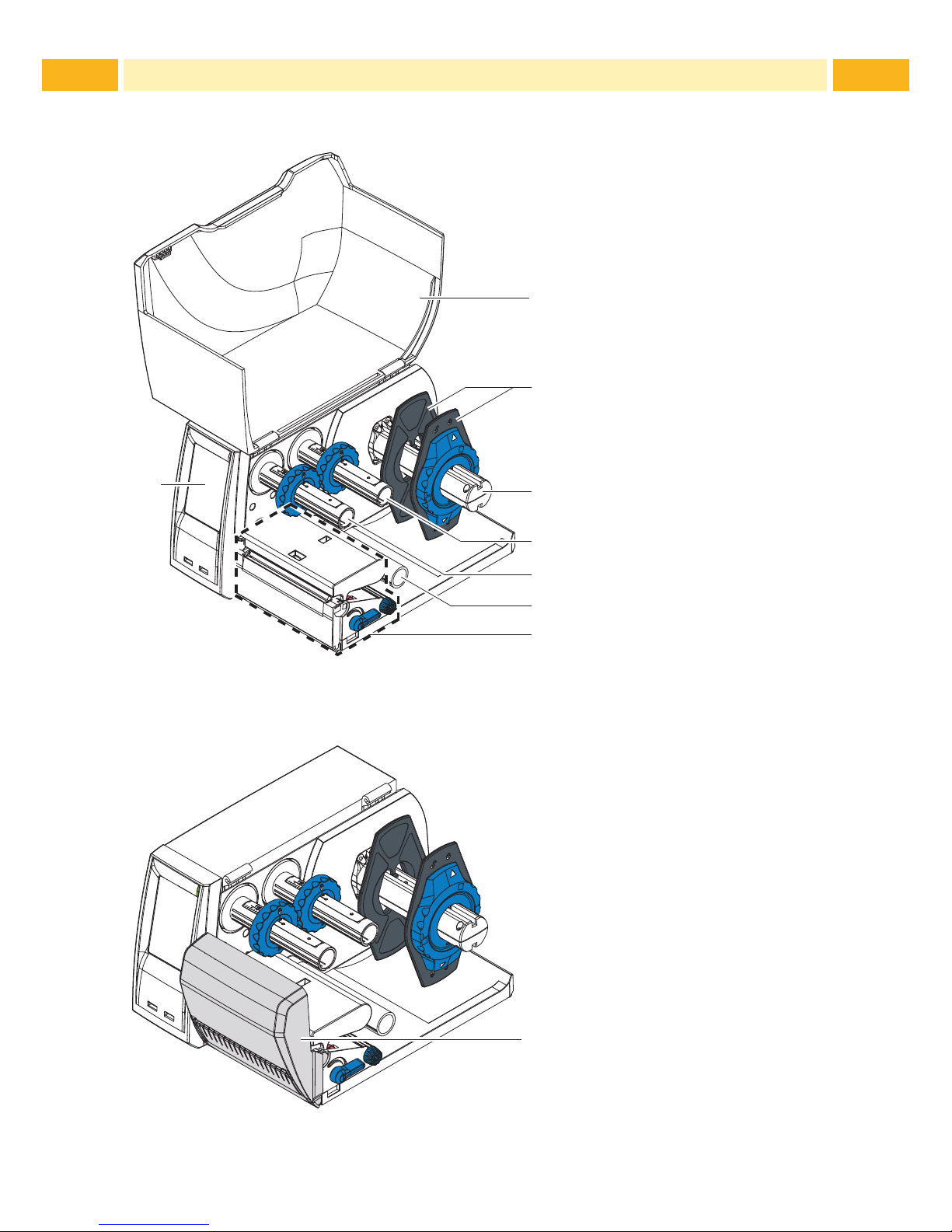
2.1 Printer Overview
1
2
3
4
5
6
7
8
1 Cover
2 Margin stops
3 Media roll retainer
4 Ribbon supply hub
5 Ribbon take-up hub
6 Roller
7 Print mechanics
8 Touchscreen display
Fig. 1 Printer with Tear-off Plate
9
9 Cutter or Perforator
Fig. 2 Printer with Cutter or Perforator
2 Installation
Page 9
9
13
15
12
10 11
1617
14
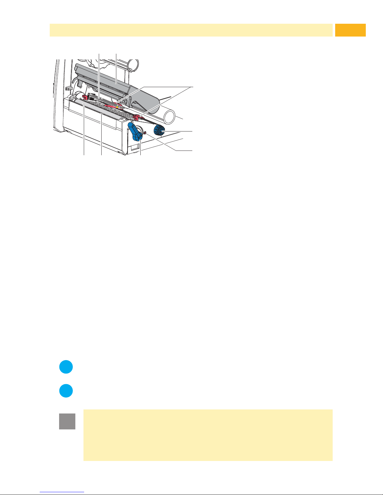
10 Media sensor
11 Printhead retainer with
printhead
12 Media guides
13 Knob for adjusting the guides
14 Knob for adjusting the media
sensor
15 Lever for locking the
printhead
16 Tear-off plate
17 Print roller
Fig. 3 Print Mechanics
2.2 Unpacking and Setting-up the Printer
Lift the printer out of the box and set it up on a level surface.
Check printer for damage which may have occurred during transport.
Check delivery for completeness.
Contents of Delivery:
• T200 Ident Printer
• Power Cable EU
• Power Cable UK
• Power Cable US
• Cardboard Core
• Operator's Manual
• DVD with demo versions of Wintotal and Printeasy, Windows driver and
documentation
• USB Cable
i
Notice!
Please keep the original packaging in case the printer must be
returned.
i
Notice!
When transporting the printer remove the transfer ribbon and media.
!
Attention!
The printer and media can be damaged by moisture and excessive
dust contamination.
Set up the Printer in a dry location protected from splashed
liquids, and sources of excessive dust.
2 Installation
Page 10
10 10
2 Installation
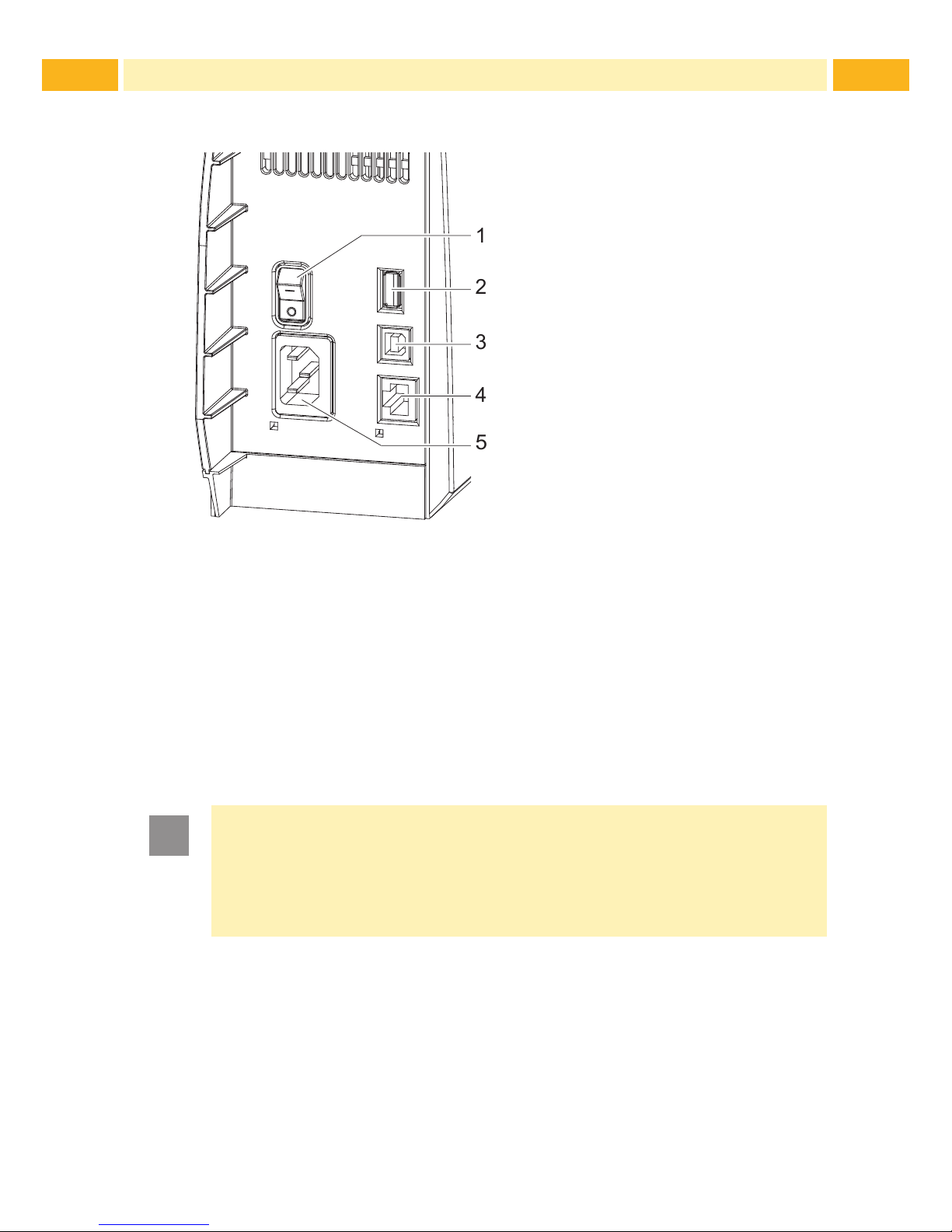
2.3 Connecting the Printer
2
3
4
5
1
1 Power switch
2 USB master ports for
keyboard, scanner or
memory stick, I
max
=500mA
3 USB full-speed slave port
4 Ethernet 10/100 Base-T
5 Power connection jack
Fig. 4 Connections
2.3.1 Connecting to the Power Supply
The printer is equipped with a wide area power unit for a supply voltage of
100 V to 240 V.
1. Check that the printer is switched off.
2. Plug the power cable into the power connection jack (5).
3. Plug the power cable into a grounded socket.
2.3.2 Connecting to a Computer or Computer Network
!
Attention!
Inadequate or no grounding can cause malfunctions during
operations.
Ensure that all computers and cables connected to the printer
are grounded.
Connect the printer to a computer or network by a suitable cable.
Page 11
11
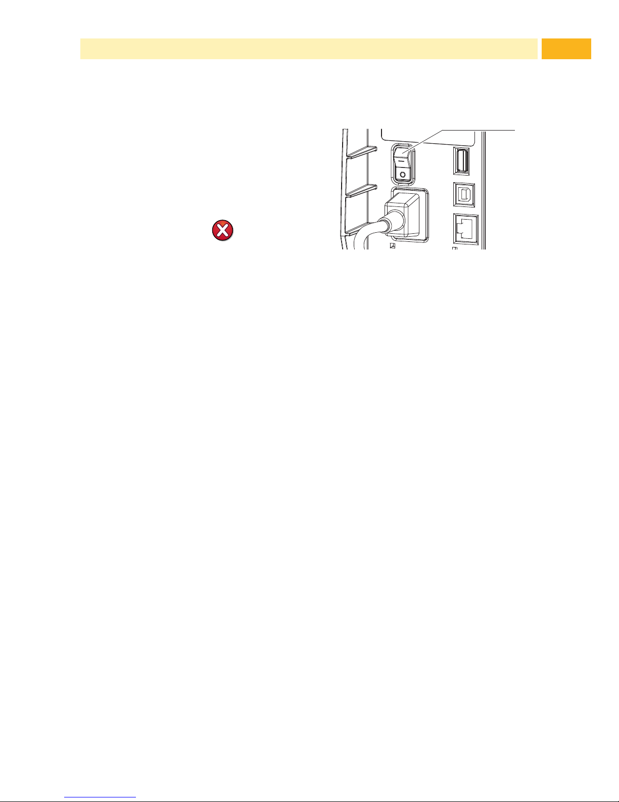
2.4 Switching on the Printer
When all connections have been
made:
Switch the printer on at the
power switch (1).
The printer performs a system
test, and then shows the system
status Ready in the display.
If an error occurs during the system
test, the symbol , Critical
fault and type of error are
displayed.
1
Fig. 5 Power Switch
2 Installation
Page 12
12 12
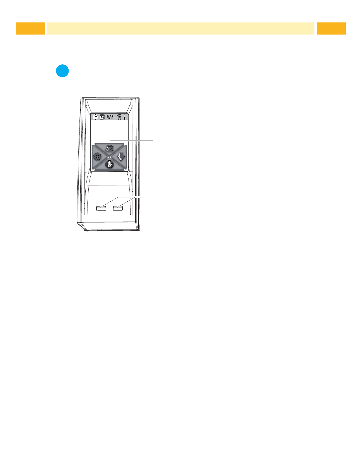
3.1 Structure of the Touchscreen Display
i
Notice!
It is advantageous, whenever possible, to make adaptations to
various print jobs in the software.
2
1
Ready
The touchscreen display (1) indicates the
current status of the printer and the print job,
indicates faults and shows the printer settings
in the menu.
By selecting the buttons on the touchscreen
display (1) settings can be made.
Two USB master ports (2/ I
max
= 100 mA) are
positioned under the touchscreen display (1).
Fig. 6 Touchscreen Display
3.2 Operating the Touchscreen Display
The touchscreen display is operated directly by touch:
• To open a menu or select a menu item lightly touch the corresponding
symbol.
• To scroll in lists slide nger up or down on the display.
3 Control Panel
Page 13

13
3 Control Panel
3.3 Symbols on the Start Display
Symbol Status Function
Ready To ofine menu
Ready Feeds a marker
Ready After the end of a print job,
reprint the last label
Printing label Interrupt print job,
printer goes into "Pause" state
Pause Continue the print job,
printer goes into "Printing label" state
Ready Delete internal memory,
the last label can no longer be reprinted.
Printing label
Press shortly g cancels the current print job
Press long g cancels the current print job
and deletes all print jobs
Pause
Table 1 Symbols on the Start Display
Page 14

14 14
3 Control Panel
3.4 Printer States
State Display Description
Ready
Ready
The printer is in the ready state and
can receive data.
Printing Label
Printing Label
and the number of the
printed label in the print
job.
The printer is currently processing
an active print job.
Data can be transmitted for a new
print job.
The new print job will start when the
previous one has nished.
Pause Pause
and the symbol
The printing process has been
interrupted by the operator.
Correctable
error
Continue
Cancel
the type of error
and the number of labels
still to be printed,
display turns red.
An error has occurred that can be
rectied by the operator without
interrupting the print job.
The print job can be continued after
the error has been rectied.
Irrecoverable
error
Cancel
the type of error
and the number of labels
still to be printed,
display turns red.
An error has occurred that cannot
be rectied without interrupting the
print job.
Critical error
Critical fault
and the type of error,
display turns red.
An error occurs during the system
test.
Switch the printer off and then
on again at the power switch.
Call Service if the fault occurs
persistently.
Power Save
Mode
If the printer is not used for a
lengthy period, it automatically
switches to power save mode.
To exit power save mode: Touch
touchscreen display.
Table 2 Printer States
Page 15

15
4.1 Loading Media from Roll
!
Attention!
The diameter of media spool greater than 170mm (6 11/16 inches )
can not be tted in the media roll retainer.
5
7
8
6
9
2
1
3
4
Fig. 7 Loading Media from Roll
1. Turn ring (2) counterclockwise, so that the arrows points to the symbol ,
and thus release the margin stop (1) from the media roll retainer (4).
2. Load media roll (3) on the roll retainer (4) in such a way that the printing
side of the media is visible from above.
3. Re-mount the margin stop (1) and push against the media roll as far as
possible.
4. Turn ring (2) clockwise, so that the arrow points to the symbol , and thus
x the margin stop (1) on the roll retainer (4).
5. Turn lever (8) counterclockwise to open printhead.
6. If the printer is equipped with a cutter or perforator, fold it down.
7. Position guides (5) by turning the knob (7) so that they are several millimeters wider than the media.
8. Position material below the roller (6) and guide it through the print unit.
!
Attention!
Guide media through the print unit below the media sensor (9).
9. Move the guides (5) closely to the edges of the media without clamping
the media.
10. Adjust media sensor ( 4.3 on page 17).
11. If the printer is equipped with a cutter / perforator, guide media through the
cutter / perforator and fold cutter / perforator back to the printing unit.
12. Press printhead retainer down and turn lever (8) clockwise to lock the
printhead.
4 Loading Media
Page 16

16 16
4 Loading Media
4.2 Loading Externally Fed and Fanfold Media
2
6
3
4
5
7
1
Fig. 8 Loading externally fed and fanfold media
1. Position media (2) behind the printer.
2. Guide the media below the roll retainer (1) to the printing unit. Ensure that
the printing side of the media is visible from above.
3. Turn lever (6) counterclockwise to open printhead.
4. If the printer is equipped with a cutter or perforator, fold it down.
5. Position guides (3) by turning the knob (5) so that they are several millimeters wider than the media.
6. Position media below the roller (4) and guide it through the print unit.
!
Attention!
Guide media through the print unit below the media sensor (7).
7. Move guides (3) closely to the edges of the media without clamping the
media.
8. Adjust media sensor ( 4.3 on page 17).
9. If the printer is equipped with a cutter / perforator, guide media through the
cutter / perforator and fold cutter / perforator back to the printing unit.
10. Press printhead down and turn lever (6) clockwise to lock the printhead.
Page 17

17
4 Loading Media
4.3 Adjusting the Media Sensor
i
Notice!
When the printer is delivered the media sensor is positioned in the
middle of the media feed. Thus, the media sensor must only be
adjusted if:
• media with reex or cut-out marks, which are not in the middle,
• multi-strip media with an even number of strips,
• media with irregularly shaped labels
are used.
1
3
2
Fig. 9 Adjusting the Media Sensor
The sensor position (3) is marked with a yellow LED in the sensor retainer.
1. Press the sensor adjustor knob (1) using a pointed object, enabling
the spring loaded sensor adjuster knob to be presented outside of the
housing.
2. Position the sensor (3) by turning the knob (1) so that the sensor can
detect the front edge of the media in the direction of paper ow or the
reex or cut-out mark.
3. Push the sensor adjuster knob (1) back into the housing using a pointed
object until it snaps into place.
Page 18

18 18
4 Loading Media
4.4 Loading Transfer Ribbon
6
52 431 1
7
8
Fig. 10 Transfer Ribbon Feed Path
C
A
B
1
Fig. 11 Edge Guide Adjustment
!
Attention!
Clean the printhead before loading the transfer ribbon
( 7.2 on page 7.2).
1. Turn lever (6) counterclockwise to open the printhead.
2. Set guide (1) on both hubs (2, 5) to the correct transfer ribbon width
(Fig. 11):
• Hold hub and unlock guide (1) by turning it clockwise in direction A.
• Slide guide in direction B and adjust guide to ribbon width using the
scale.
• Hold hub and lock edge guide by turning it counterclockwise in
direction C.
3. Load transfer ribbon (4) on the hub (5) up to the edge guide (1) in a way
that the ink coating of the ribbon faces the opposite side of the print head
after being loaded.
i
Notice!
To wind the ribbon an empty ribbon core (3) is needed that must be
at least equal in width to the supply ribbon.
When changing the transfer ribbon use the empty supply ribbon
core for winding the next ribbon.
4. Adjust position of the edge guide on the take-up hub to the width of the
ribbon core (3) and push ribbon core on the take-up hub (2).
5. Guide the transfer ribbon through the printing unit as shown in Fig. 10 in
a way that the ink coating (8) of the ribbon contacts on the media to be
printed NOT the printhead.
Page 19

19
4 Loading Media
!
Attention!
Guide transfer ribbon over the media sensor (7).
6. Secure the starting end of the transfer ribbon to the ribbon core (3) using
adhesive tape. Ensure counterclockwise rotation direction of the transfer
ribbon take-up hub (2).
7. Turn the transfer ribbon take-up hub (2) counterclockwise to smooth out the
feed path of the transfer ribbon.
8. Press the printhead down and turn lever (6) clockwise to lock printhead.
4.5 Setting the Feed Path of the Transfer Ribbon
Transfer ribbon wrinkling can lead to print image errors. Transfer ribbon
deection can be adjusted so as to prevent wrinkles.
1
Fig. 12 Setting the Feed Path of the Transfer Ribbon
i
Notice!
The adjustment is best carried out during printing.
Turn screw (1) with torx wrench TX10 and observe the behavior of the
ribbon.
• By turning it clockwise the outer edge of the transfer ribbon is
tightened.
• By turning it counterclockwise the inner edge of the transfer ribbon is
tightened.
Page 20

20 20
5 Cutter / Perforator (Option)
The cutter / perforator must be mounted to the printer during initial setup.
2
4
5
1
3
1
Fig. 13 Mount Cutter or Perforator
1. Put snap arm (5) of the cutter / perforator with the groove (4) rst into the
guide on the retainer (2).
2. Push the cutter / perforator (1) down into the holders (3).
3. Fold up the cutter / perforator (1) so that it snaps on both sides of the
retainer (2).
i
Notice!
When setting up the perforator please consult TE document
"T200 Ident Perforator setup instruction"(411-121015) found
on the DVD enclosed in the printer box and enclosed in the
Perforator box.
Page 21

21
6 Printing Operation
!
Attention!
Printhead damage is caused by improper handling!
Do not touch the underside of the printhead with ngers or
sharp objects.
Ensure the media is clean by storing in a clean environment.
The printer is ready for operation when all of the connections have been
made, and the media and the transfer ribbon has been loaded.
6.1 Printing in Tear-off Mode (For Labels only)
After printing, the label can be torn-off manually. The printer is equipped with a
tear-off plate for this purpose.
6.2 Printing in Cutting Mode
The printer can be equipped with a cutter or perforator, to cut off or perforate
labels or continuous media automatically after printing.
6.3 Synchronizing the Media Feed
After the media has been inserted for cutting, calibration (synchronization) is
required. The rst media section detected by the media sensor is transported
to the print position, with all media sections before being fed out of the printer.
This calibration (synchronization), will avoid an incorrectly cut media section
length (too long).
Press to start the calibration (synchronization).
Remove the blank media sections cut during the calibration
(synchronization).
i
Notice!
Calibration (synchronization) is not necessary if the printhead was
not opened between different print jobs, even if the printer was
switched off.
Page 22

22 22
7 Maintenance
7.1 Cleaning Instructions
Danger!
Risk of death from electric shock!
Disconnect the printer from the power supply before performing
any maintenance work.
It is important to clean the thermal printhead regularly. This guarantees a
consistently good printed image and reduces wear of the printhead.
Otherwise, the maintenance is limited to monthly cleaning of the printer.
!
Attention!
The printer can be damaged by aggressive cleansers.
Do not use abrasive cleaning materials, always use TE recom-
mended cleaning products.
For ordering information please contact your local TE representative, or use the contact details on page 2 of this Manual.
Remove dust and paper uff from the print area with a soft brush or
vacuum cleaner.
7.2 Cleaning the Printhead
Cleaning intervals: - every ribbon roll change
Substances may accumulate on the printhead during printing and adversely
affect printing.
!
Attention!
Printhead damage is caused by improper handling!
Do not touch the underside of the printhead with ngers or
sharp objects.
!
Attention!
Risk of injury from the hot printhead line.
Ensure that the printhead has cooled down before starting
cleaning.
Page 23

23
1
Fig. 14 Printhead Line
1. Lift the printhead.
2. Remove media and transfer ribbon from the printer.
3. Clean printhead line(1) with TE recommended cleaning materials.
4. Allow the printhead to dry for 2 - 3 minutes before commencing printing.
7.3 Changing the Printhead
2
6
7
1 5
8
3 4
2
Fig. 15 Printhead
1. Fold up printhead retainer (5).
2. Remove media and ribbon from the printer.
3. Push the printhead (1) up against the printhead retainer, slide the holding
lug (2) over the web (6) and pull it out of the slot in the printhead retainer.
4. Remove the printhead from the guide (6) in the printhead retainer.
5. Detach the cables (3 and 4) from the printhead.
6. After changing the printhead, attach the cables (3 and 4) to the printhead.
7. Insert the holding lug (7) of the printhead into the guide (6) in the retainer.
8. Push printhead (1) up against the printhead retainer. While doing so, guide
the holding lug (2) of the printhead upwards through the slot in the retainer.
9. Slide the printhead into the printhead retainer until the holding lug (2)
latches over the web (6).
7 Maintenance
Page 24

24 24
7.4 Cleaning or Replacing the Print Roller
Accumulations of dirt on the print roller may impair the media transport and
the print quality.
!
Attention!
Damage of the print roller.
Do not use sharp objects (knives, screwdrivers, etc.) to clean
the print roller.
1
43 35
2
Fig. 16 Print Roller
1. Turn lever (2) counterclockwise to open printhead.
2. Remove media and transfer ribbon from the printer.
3. Fold down the cover (5) with the tear-off plate, cutter or perforator.
4. Lift the print roller (4) from its retainers (3).
5. Remove deposits with the TE recommended roller cleaner and a soft cloth,
or replace the roller if it appears damaged.
6. Push the bearings of the print roller (1) into the retainer (3) until they click
into place.
7. Fold up the cover (5) with the tear-off plate, cutter or perforator.
7 Maintenance
Page 25

25
7 Maintenance
7.5 Cleaning Cutter / Perforator and Replace Blades
!
Warning!
Disconnect printer from the power supply to prevent accidental
blade movement.
!
Warning!
Risk of injury! The cutter / perforator blades are sharp!
i
Notice!
When cutting through the label material instead of the label gap
remains of adhesive may accumulate on the blades. If operating in
backfeed mode, such remains of adhesive may be deposited on the
drive roller as well.
Clean the drive roller and the cutter / perforator blades often.
1
2
3
4
Fig. 17 Dismount Cutter / Perforator
1. Fold down the cutter / perforator.
2. Push the release push button (1) and lift the blade unit (3) from the cover
(4).
3. If the blades are only slightly dirty it is sufcient to clean them with a soft
cloth and continue with point 5.
Page 26

26 26
7 Maintenance
9
10
11
5
8
7
8
7
5
6
Fig. 18 Replace Blades
1312
Fig. 19 Springs
4. If the blades are very dirty with residues of adhesive or if they are worn,
change blades:
Turn the shaft (6) clockwise using a torx wrench TX10 until the gear
racks (7) no longer engage.
Pull the upper blade (9) out of the guides (8).
Take out the lower blade (10).
Remove deposits from the blades with TE approved cleaning
materials.
If necessary, replace blades.
Push the lower blade down into the guides (11).
If necessary, put springs (12) back into spring retainers (13).
To re-mount the upper blade push the lower blade down on the cover
and push the upper blade into the guide until the gear racks (7) can
engage with the gear wheels (5).
Turn the shaft (6) counterclockwise using a torx wrench TX10 until the
blade reaches the upper limit.
5. Fit the blade unit (3) according to Fig. 17 into the axes (2) and fold it
towards the cover (4) until it snaps in.
6. Fold the cutter / perforator up to the print unit.
Page 27

27
8.1 Types of Errors
The diagnostic system indicates an error on the touchscreen display when an
error occurs.
State Display Button
Correctable error
Continue, Cancel
Display turns red
Irrecoverable error
Cancel
Display turns red
Critical fault
Cancel
Display turns red
Table 3 Error States
8.2 Problem Solution
Problem Cause Remedy
Horizontal white lines in the
print image
Printer is used with the
backfeed > smart in
the cut or
peel-off mode
Set the backfeed >
always in the setup.
Print image has smears or
voids
Printhead is dirty Clean the printhead
7.2 on page 22
Temperature too high Decrease temperature
via software.
Unsuitable combination
of media and transfer
ribbon
Always use TE
Connectivity approved
products. Consult the
Identication TT Printer
Product Ribbon matrix
(411-121005)
Printer only prints every
second label
Setting of the size in the
software is too large.
Adjust the dimensions of
the media template in the
software.
Printer prints a sequence
of characters instead of the
label format
Printer is in ASCII dump
mode
Cancel the ASCII dump
mode.
Transfer ribbon wrinkles Transfer ribbon feed
path not adjusted
Adjust transfer ribbon
feed path 4.5 on page
19
Transfer ribbon too wide Use transfer ribbon only
a little wider than the
media.
8 Fault Correction
Page 28

28 28
Problem Cause Remedy
Vertical white lines in the
print image
Printhead is dirty Clean the printhead.
7.2 on page 22
Printhead is defective
(failure of heat
elements)
Change the printhead.
7.3 on page 23
Table 4 Problem Solution
8 Fault Correction
Page 29

29
8 Fault Correction
8.3 Error Messages and Fault Correction
Error message Cause Remedy
Barcode too
big
The barcode is too big for the
allocated area of the media
Reduce the size of the barcode
or move it.
Barcode
error
Invalid barcode content, e.g.
alphanumeric characters in a
numerical barcode
Correct the barcode content.
Buffer
overow
The input buffer memory is
full and the computer is still
transmitting data.
Use data transmission via
protocol (preferably RTS/CTS).
Card full
No more data can be stored
on the medium.
Replace medium.
Cutter
blocked
Cutter / perforator cannot
return into its home position
and stays in an undened
position
Material too thick or hard,
cutter / perforator does not
cut through material but can
return to initial position.
Switch off the printer. Remove
material. Switch on the printer.
Restart print job.
Check material
No cutter / perforator function Switch the printer off and then
on.
If error recurs call support.
Device not
conn.
Programming addresses a
non-existent device
Either connect this device or
correct the programming.
File not
found
Requested le is not on the
data medium
Check the contents of the data
medium.
Font not
found
Error with the selected
download font
Cancel current print job, change
font.
Head open
Printhead not locked Lock printhead.
Head too hot
Printhead is overheated After pausing the print job will
be continued automatically.
If the fault recurs repeatedly,
reduce the heat level or the print
speed via software.
Material too
thick
Material too thick or hard,
cutter / perforator does not
cut through material but can
return to initial position.
Cancel print job.
Check material.
Blunt blades
Clean or change blades 7.5
on page 25
Page 30

30 30
8 Fault Correction
Error message Cause Remedy
Memory
overow
Current print job contains
too much information, e.g.
selected font, large graphics
Cancel current print job.
Reduce amount of data to be
printed.
Name exists
Duplicate usage of eld name
in the direct programming
Correct programming
Network
Error
e.g. No DHCP server, no
link, no SMTP server, no
Timeserver
Please contact your network
administrator.
No label
found
There are labels missing on
the label material
Press Continue repeatedly until
printer recognizes the next label
on the material.
The label format as set in the
software does not correspond
with the real label format
Cancel current print job.
Change the label format set in
the software.
Restart print job.
Printer is loaded with
continuous paper, but the
software is set on labels
Cancel current print job.
Change the label format set in
the software.
Restart the print job.
No label
size
The size of the label is not
dened in the programming.
Check programming.
Out of paper
Out of label roll Load labels.
Error in the paper feed,
Material is not positioned
under the media sensor.
Check paper feed.
Out of
ribbon
Out of transfer ribbon Insert new transfer ribbon.
Transfer ribbon melted during
printing
Cancel current print job.
Change the heat level via
software.
Clean the printhead 7.2 on
page 22
Load transfer ribbon
Restart print job.
Protocol
error
Printer has received an
unknown or invalid command
from the computer, e.g.
the command to perform a
cut although a cutter is not
mounted
Select Continue to skip the
command or
select Cancel to cancel the print
job.
Read error
Read error when reading
from the data medium.
Check data medium.
Backup data, reformat medium.
Page 31

31
Error message Cause Remedy
Structural
err.
Error in the le list of the
data medium, data access is
uncertain.
Format data medium.
System Error
e.g. FPGA defective, invalid
setup, voltage error
Switch the printer off and then
on. Please note error details
shown on the display.
If error recurs call support.
Unknown card
Data medium not formatted. Format data medium.
Type of data medium not
supported.
Use different type of data
medium.
USB error
e.g. Too much current, no
reaction, unknown device
Do not use the USB device.
Write error
Hardware error Repeat the write process,
reformat card.
Write
protected
Data medium write protection
is activated.
Deactivate the write protection.
Table 5 Error Messages and Fault Correction
8 Fault Correction
Page 32

32 32
9 Licences
9.1 EC Declaration of Conformity
Tyco Electronics UK Ltd
Faraday Road
Dorcan, Swindon
Wiltshire
SN3 5HH
UK
EC Declaration of Conformity
We declare herewith that as a result of the manner in which the device designated
below was designed, the type of construction and the devices which, as a result have
been brought on to the general market comply with the relevant fundamental regulations of the EC Rules for Safety and Health. In the event of any alteration which
has not been approved by us being made to any device as designated below, this
statement shall thereby be made invalid.
Device: Thermal Transfer Printer
Type: T200 IDENT
Applied EC Regulations and Standards:
Directive 2006/95/EC relating to
electrical equipment designed for
use within certain voltage limits
• EN 60950-1:2006+A11:2009
• EN 61558-1:2005+A1:2009
Directive 2004/108/EC relating to
electromagnetic compatibility
• EN 55022:2010
• EN 55024:2010
• EN 61000-3-2:2006+A1:2009+A2:2009
• EN 61000-3-3:2008
• EN 61000-6-2:2005
Signed for, and on behalf of the
Manufacturer :
Tyco Electronics UK Ltd
Faraday Road,
Dorcan, Swindon,
Wiltshire
SN3 5HH, UK
Mario Appello
Global Engineering Manager
Page 33

33
9.2 FCC
NOTE : This equipment has been tested and found to comply with the
limits for a Class A digital device, pursuant to Part 15 of the FCC Rules.
These limits are designed to provide reasonable protection against
harmful interference when the equipment is operated in a commercial
environment. The equipment generates, uses, and can radiate radio
frequency and, if not installed and used in accordance with the
instruction manual, may cause harmful interference to radio communications. Operation of this equipment in a residential area is likely to cause
harmful interference in which case the user may be required to correct
the interference at his own expense.
9.3 Open Source Software Information
This TE product includes software code developed by third parties, including software
code subject to the GNU General Public License version 3 from June 29, 2007
("GPL"); GNU Lesser General Public License version 3 from June 29, 2007 ("LGPL");
Academic Free License version 2.1; Yabasic Artistic License; FreeType Project
License of January 27, 2006; Berkeley Software Distribution Licenses (“BSD”); and
Mozilla Public License Version 1.1 (“Mozilla”). Your use of this product constitutes
express acceptance of the applicable license agreements, and if you do not agree
with the terms of these license agreements, please do not use this product but
instead return it unused to the place you purchased this product. The terms of the
GPL and LGPL are available at GNU’s ofcial website www.gnu.org . If you require
information on obtaining access to the code subject to GPL and LGPL used in this
product, please send your inquiry to:
Identication (Open source inquiry)
Tyco Electronics UK Ltd
Faraday Road
Dorcan
Swindon
Wiltshire
SN3 5HH
UK
The code subject to GPL and LGPL used in this product are distributed WITHOUT
ANY WARRANTY and are subject to the copyrights of one or more of their respective
authors and the terms of their respective license agreements.
To obtain a copy of the Standard Version of Yabasic, see www.yabasic.de;
for information on modications of the Standard Version of Yabasic, see www.cab.de/
tw/templates/pushle.cfm?le=1507.
9 Licences
Page 34

34 34
9 Licences
The software in this product is based in part of the work of the FreeType Team.
Nano-X is distributed under Mozilla, and source code for Nano-X and any modications thereto in this product are available under the terms of Mozilla by sending an
inquiry to the above address*.
Libsnmp is subject to various copyrights under these BSD licenses:
---- Part 1: CMU/UCD copyright notice: (BSD like) -----
Copyright 1989, 1991, 1992 by Carnegie Mellon University
Derivative Work - 1996, 1998-2000
Copyright 1996, 1998-2000 The Regents of the University of California
All Rights Reserved
Permission to use, copy, modify and distribute this software and its documentation for any purpose and without fee is hereby granted, provided that the above
copyright notice appears in all copies and that both that copyright notice and this
permission notice appear in supporting documentation, and that the name of CMU
and The Regents of the University of California not be used in advertising or publicity
pertaining to distribution of the software without specic written permission.
CMU AND THE REGENTS OF THE UNIVERSITY OF CALIFORNIA DISCLAIM ALL
WARRANTIES WITH REGARD TO THIS SOFTWARE, INCLUDING ALL IMPLIED
WARRANTIES OF MERCHANTABILITY AND FITNESS. IN NO EVENT SHALL
CMU OR THE REGENTS OF THE UNIVERSITY OF CALIFORNIA BE LIABLE FOR
ANY SPECIAL, INDIRECT OR CONSEQUENTIAL DAMAGES OR ANY DAMAGES
WHATSOEVER RESULTING FROM THE LOSS OF USE, DATA OR PROFITS,
WHETHER IN AN ACTION OF CONTRACT, NEGLIGENCE OR OTHER TORTIOUS
ACTION, ARISING OUT OF OR IN CONNECTION WITH THE USE OR PERFORMANCE OF THIS SOFTWARE.
Page 35

35
9 Licences
---- Part 2: Networks Associates Technology, Inc copyright notice (BSD) -----
Copyright (c) 2001-2003, Networks Associates Technology, Inc
All rights reserved.
Redistribution and use in source and binary forms, with or without modication, are
permitted provided that the following conditions are met:
* Redistributions of source code must retain the above copyright notice,
this list of conditions and the following disclaimer.
* Redistributions in binary form must reproduce the above copyright notice,
this list of conditions and the following disclaimer in the documentation and/or other
materials provided with the distribution.
* Neither the name of the Networks Associates Technology, Inc nor the names of its
contributors may be used to endorse or promote products derived from this
software without specic prior written permission.
THIS SOFTWARE IS PROVIDED BY THE COPYRIGHT HOLDERS AND CONTRIBUTORS ``AS IS'' AND ANY EXPRESS OR IMPLIED WARRANTIES, INCLUDING,
BUT NOT LIMITED TO, THE IMPLIED WARRANTIES OF MERCHANTABILITY
AND FITNESS FOR A PARTICULAR PURPOSE ARE DISCLAIMED. IN NO EVENT
SHALL THE COPYRIGHT HOLDERS OR CONTRIBUTORS BE LIABLE FOR
ANY DIRECT, INDIRECT, INCIDENTAL, SPECIAL, EXEMPLARY, OR CONSEQUENTIAL DAMAGES (INCLUDING, BUT NOT LIMITED TO, PROCUREMENT OF
SUBSTITUTE GOODS OR SERVICES; LOSS OF USE, DATA, OR PROFITS; OR
BUSINESS INTERRUPTION) HOWEVER CAUSED AND ON ANY THEORY OF
LIABILITY, WHETHER IN CONTRACT, STRICT LIABILITY, OR TORT (INCLUDING
NEGLIGENCE OR OTHERWISE) ARISING IN ANY WAY OUT OF THE USE OF
THIS SOFTWARE, EVEN IF ADVISED OF THE POSSIBILITY OF SUCH DAMAGE.
Page 36

36 36
9 Licences
---- Part 3: Cambridge Broadband Ltd. copyright notice (BSD) -----
Portions of this code are copyright (c) 2001-2003, Cambridge Broadband Ltd.
All rights reserved.
Redistribution and use in source and binary forms, with or without
modication, are permitted provided that the following conditions are met:
* Redistributions of source code must retain the above copyright notice,
this list of conditions and the following disclaimer.
* Redistributions in binary form must reproduce the above copyright notice,
this list of conditions and the following disclaimer in the documentation and/or
other materials provided with the distribution.
* The name of Cambridge Broadband Ltd. may not be used to endorse or promote
products derived from this software without specic prior written permission.
THIS SOFTWARE IS PROVIDED BY THE COPYRIGHT HOLDER ``AS IS'' AND
ANY EXPRESS OR IMPLIED WARRANTIES, INCLUDING, BUT NOT LIMITED
TO, THE IMPLIED WARRANTIES OF MERCHANTABILITY AND FITNESS FOR
A PARTICULAR PURPOSE ARE DISCLAIMED. IN NO EVENT SHALL THE
COPYRIGHT HOLDER BE LIABLE FOR ANY DIRECT, INDIRECT, INCIDENTAL,
SPECIAL, EXEMPLARY, OR CONSEQUENTIAL DAMAGES (INCLUDING, BUT
NOT LIMITED TO, PROCUREMENT OF SUBSTITUTE GOODS OR SERVICES;
LOSS OF USE, DATA, OR PROFITS; OR BUSINESS INTERRUPTION) HOWEVER
CAUSED AND ON ANY THEORY OF LIABILITY, WHETHER IN CONTRACT,
STRICT LIABILITY, OR TORT (INCLUDING NEGLIGENCE OR OTHERWISE)
ARISING IN ANY WAY OUT OF THE USE OF THIS SOFTWARE, EVEN IF
ADVISED OF THE POSSIBILITY OF SUCH DAMAGE.
Page 37

37
9 Licences
---- Part 4: Sun Microsystems, Inc. copyright notice (BSD) -----
Copyright © 2003 Sun Microsystems, Inc., 4150 Network Circle, Santa Clara,
California 95054, U.S.A. All rights reserved.
Use is subject to license terms below.
This distribution may include materials developed by third parties.
Sun, Sun Microsystems, the Sun logo and Solaris are trademarks or registered
trademarks of Sun Microsystems, Inc. in the U.S. and other countries.
Redistribution and use in source and binary forms, with or without modication, are
permitted provided that the following conditions are met:
Redistributions of source code must retain the above copyright notice, this list of
conditions and the following disclaimer.
Redistributions in binary form must reproduce the above copyright notice, this list of
conditions and the following disclaimer in the documentation and or other materials
provided with the distribution.
Neither the name of the Sun Microsystems, Inc. nor the names of its contributors
may be used to endorse or promote products derived from this software without
specic prior written permission.
THIS SOFTWARE IS PROVIDED BY THE COPYRIGHT HOLDERS AND CONTRIBUTORS ``ASIS'' AND ANY EXPRESS OR IMPLIED WARRANTIES, INCLUDING,
BUT NOT LIMITED TO,THE IMPLIED WARRANTIES OF MERCHANTABILITY AND
FITNESS FOR A PARTICULAR PURPOSE ARE DISCLAIMED. IN NO EVENT
SHALL THE COPYRIGHT HOLDERS OR CONTRIBUTORS BE LIABLE FOR
ANY DIRECT, INDIRECT, INCIDENTAL, SPECIAL,EXEMPLARY, OR CONSEQUENTIAL DAMAGES (INCLUDING, BUT NOT LIMITED TO,PROCUREMENT OF
SUBSTITUTE GOODS OR SERVICES; LOSS OF USE, DATA, OR PROFITS;OR
BUSINESS INTERRUPTION) HOWEVER CAUSED AND ON ANY THEORY OF
LIABILITY,WHETHER IN CONTRACT, STRICT LIABILITY, OR TORT (INCLUDING
NEGLIGENCE OR OTHERWISE) ARISING IN ANY WAY OUT OF THE USE OF
THIS SOFTWARE, EVEN IF ADVISED OF THE POSSIBILITY OF SUCH DAMAGE.
Page 38

38 38
9 Licences
---- Part 5: Sparta, Inc copyright notice (BSD) -----
Copyright (c) 2003-2009, Sparta, Inc All rights reserved. Redistribution and use in
source and binary forms, with or without Modication, are permitted provided that
the following conditions are met: * Redistributions of source code must retain the
above copyright notice, this list of conditions and the following disclaimer. * Redistributions in binary form must reproduce the above copyright notice, this list of
conditions and the following disclaimer in the documentation and/or other materials
provided with the distribution. * Neither the name of Sparta, Inc nor the names of its
contributors may be used to endorse or promote products derived from this software
without specic prior written permission. THIS SOFTWARE IS PROVIDED BY THE
COPYRIGHT HOLDERS AND CONTRIBUTORS ``ASIS'' AND ANY EXPRESS
OR IMPLIED WARRANTIES, INCLUDING, BUT NOT LIMITED TO,THE IMPLIED
WARRANTIES OF MERCHANTABILITY AND FITNESS FOR A PARTICULAR
PURPOSE ARE DISCLAIMED. IN NO EVENT SHALL THE COPYRIGHT HOLDERS
OR CONTRIBUTORS BE LIABLE FOR ANY DIRECT, INDIRECT, INCIDENTAL,
SPECIAL,EXEMPLARY, OR CONSEQUENTIAL DAMAGES (INCLUDING, BUT
NOT LIMITED TO,PROCUREMENT OF SUBSTITUTE GOODS OR SERVICES;
LOSS OF USE, DATA, OR PROFITS;OR BUSINESS INTERRUPTION) HOWEVER
CAUSED AND ON ANY THEORY OF LIABILITY,WHETHER IN CONTRACT, STRICT
LIABILITY, OR TORT (INCLUDING NEGLIGENCE OR OTHERWISE) ARISING IN
ANY WAY OUT OF THE USE OF THIS SOFTWARE, EVEN IF ADVISED OF THE
POSSIBILITY OF SUCH DAMAGE.
---- Part 6: Cisco/BUPTNIC copyright notice (BSD) -----
Copyright (c) 2004, Cisco, Inc and Information Network Center of Beijing University
of Posts and Telecommunications. All rights reserved. Redistribution and use in
source and binary forms, with or without Modication, are permitted provided that the
following conditions are met: * Redistributions of source code must retain the above
copyright notice, this list of conditions and the following disclaimer. * Redistributions in binary form must reproduce the above copyright notice, this list of conditions
and the following disclaimer in the documentation and/or other materials provided
with the distribution. * Neither the name of Cisco, Inc, Beijing University of Posts
and Telecommunications, nor the names of their contributors may be used to
endorse or promote products derived from this software without specic prior written
permission. THIS SOFTWARE IS PROVIDED BY THE COPYRIGHT HOLDERS
AND CONTRIBUTORS ``ASIS'' AND ANY EXPRESS OR IMPLIED WARRANTIES,
INCLUDING, BUT NOT LIMITED TO,THE IMPLIED WARRANTIES OF MERCHANTABILITY AND FITNESS FOR A PARTICULAR PURPOSE ARE DISCLAIMED. IN
NO EVENT SHALL THE COPYRIGHT HOLDERS OR CONTRIBUTORS BE LIABLE
FOR ANY DIRECT, INDIRECT, INCIDENTAL, SPECIAL,EXEMPLARY, OR CONSEQUENTIAL DAMAGES (INCLUDING, BUT NOT LIMITED TO,PROCUREMENT OF
SUBSTITUTE GOODS OR SERVICES; LOSS OF USE, DATA, OR PROFITS;OR
BUSINESS INTERRUPTION)
Page 39

39
C
Cleaning
Cutter / Perforator .......25
Printhead .....................22
Print Roller ..................24
Cleaning Instructions .........22
Connecting ........................10
Contents of delivery .............9
Correctable error ...............14
Critical error .......................14
D
Device overview ..................8
E
Environment ........................7
Errors .................................27
Correction ......................7
Display ..........................7
Messages ....................30
States ............................7
Types .............................7
I
Important information...........5
Instructions ..........................5
Intended use ........................6
Irrecoverable error .............14
L
Lithium battery .....................7
Loading externally fed and
fanfold media .....................16
Loading media ...................15
Loading media from roll .....15
Loading transfer ribbon......18
M
Margin stops ........................8
Modications........................7
P
Pause ................................14
Power save mode ..............14
Power supply .....................10
Printer states .....................14
Printhead
Cleaning ......................22
Damage .................21, 22
Printing label ......................14
Problem solution ................27
R
Ready ................................14
Recycling .............................7
Ribbon deection, setting ..19
S
Safety instructions ...............6
Service work ........................7
Setting-up ............................9
Supply voltage ...................10
Switching on the printer ..... 11
Symbols .............................13
Synchronizing the media
feed....................................21
T
Tear-off mode ....................21
Touchscreen display ..........12
U
Unpacking............................9
W
Warning stickers ..................7
10 Index
Page 40

Tyco Electronics UK Ltd
Faraday Road
Dorcan,
Swindon
Wiltshire
SN3 5HH
UK
 Loading...