

Page 1

Integra Ci3 digital metering system
1. Features and options
The Integra Ci3 digital meter is designed for accurate measurement and display of all major electrical and p ower
quality parameters. It is has been designed, developed and manufactured in the UK, by Crompton Instruments.
It is user programmable to suit single-phase two wire, three-phase three-wire, and three-phase four-wire system
configurations.
The product features a DIN 96 panel mounted snap-fit enclosure, backlit Liquid Crystal Display (LCD) and user
programmable CT ratios, accessible via an intuitive user interface. The Integra Ci3 digital meter measures 17
electrical parameters including total harmonic distortion (THD) up to the 31st harmonic.
The Integra Ci3 digital meter offers two output ports at the rear of the product. This allows to fit either two
isolated pulsed output relays or a RS-485 communication module to allow Modbus protocol or John son Controls
communication output. These are configurable via internal settings.
1.1 Power Supply
The Integra Ci3 digital meter must be powered from an auxiliary AC or DC supply that is separate (but it may
also be commoned) from the metered supply. The input range of the auxiliary is 110-400V AC or 120-350V
DC. All connections are made to screw clamp terminals that accept 0.05 - 2.5mm
cables. Terminal screws are fully tightened for shipment and must be undone before wire insertion.
Terminal screws should be tightened to 0.5 Nm (4.4 lbf in) only.
1.2 RS485 Module Option
An optional RS485 module is available for purchase. Where a RS485 module is available, it can be
connected to a PC for control and monitoring purposes using either Modbus protocol or Johnson Controls
protocol. A maximum of one RS485 module can be fitted to an Integra Ci3 digital meter.
1.3 Pulse Relay Module Option
An optional Pulsed Relay module is available for purchase. Pulse relays are user programmable for
corresponding energy type, pulse divisor (one pulse for every 0.1, 1, 10, 100 or 1000kWh/kVArh for
example) and pulse width (duration). A maximum of two Pulsed Relay modules can be fitted to an Integra
Ci3 digital meter, when no RS485 module is fitted. When two Pulsed Relay modules are fitted, they share a
common divisor value and pulse width.
1.4 Display Screen
The display screen is used in two main modes: display of measured values and parameter setup.
1.5 Front Panel Buttons
The front of the product has four buttons that select different electrical parameters and are also used for
system configuration.
is used to select the Voltage and Frequency parameter screens.
In set-up mode this is the “Back” button.
is used to select the Current parameter screens.
In set-up mode this is the “Up” button.
is used to select the Power and Power Factor parameter screens.
In set-up mode this is the “Down” button.
2
stranded or solid core
Installation instruction
Project 2187 Drawing No. CI-3K51101 Rev 10
DMR 2720 18/07/11
1
Modbus is a Trademark of Schneider Automation Inc. Other Trademarks or company
names mentioned herein are the property of their respective owners.
Page 2
is used to select the Energy parameter screens.
In set-up mode this is the “Enter” button.
1.6 Display Mode
The parameters are viewed on a backlit LCD screen. There are 15 screens accessible via 4 buttons on the
front panel allowing the user to navigate between the various screens.
1.7 Set Up Mode
In Set Up mode, the top row shows an abbreviation of the parameter name, the middle row shows the
parameter value being set and the bottom row is used to confirm the input has been “set” to the desired
value. In general, the
and buttons change a parameter value and the key enters the value.
1.8 Start Up Screens
When power is initially applied to the Integra Ci3 digital meter, it progresses through a series of three startup screens. The first screen provides a visual check of the LCD screen by lighting up all the LCD segments.
The second displays the unit’s firmware version; whilst the third displays a start-up self test result. If this self
test is successful, the unit then switches to the default “Voltage” screen.
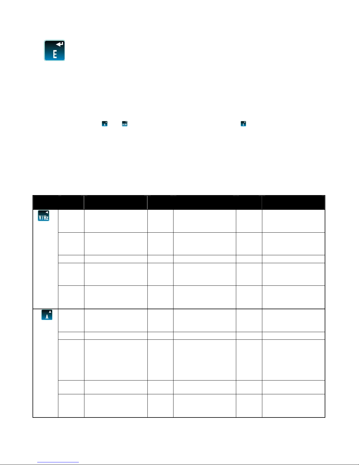
2. Display mode screen sequence (4 wire)
Button
Screen
No.
1 Volts L1 – N 1 Volts L1 -L2 1 Volts L1
Description
3 phase 4 wire
Screen
No.
3 phase 3 wire
Screen
No.
1phase 2 wire
Volts L2 - N Volts L2 - L3
Volts L3 - N Volts L3 - L1
2 Volts L1 -L2
Volts L2 - L3
Volts L3 - L1
3 Frequency 2 Frequency 2 Frequency
4 Volts L1 - N THD%
Volts L2 - N THD%
Volts L3 - N THD%
5 Volts L1 -L2 THD% 3 Volts L1 -L2 THD% 3 Volts L1 THD%
Volts L2 - L3 THD% Volts L2 - L3 THD%
Volts L3 - L1 THD% Volts L3 - L1 THD%
1 Current L1 1 Current L1 1 Current L1
Current L2 Current L2
Current L3 Current L3
2 Neutral Current
3
L1 Current Max
Demand
2
L2 Current Max
Demand
L3 Current Max
Demand
L1 Current Max
Demand
2
L1 Current Max
Demand
L2 Current Max
Demand
L3 Current Max
Demand
Neutral Current Max
4
Demand
5 Current L1 THD% 3 Current L1 THD% 3 Current L1 THD%
Current L2 THD% Current L2 THD%
Current L3 THD% Current L3 THD%
Project 2187 Drawing No. CI-3K51101 Rev 10
DMR 2720 18/07/11
2
Modbus is a Trademark of Schneider Automation Inc. Other Trademarks or company
names mentioned herein are the property of their respective owners.
Page 3
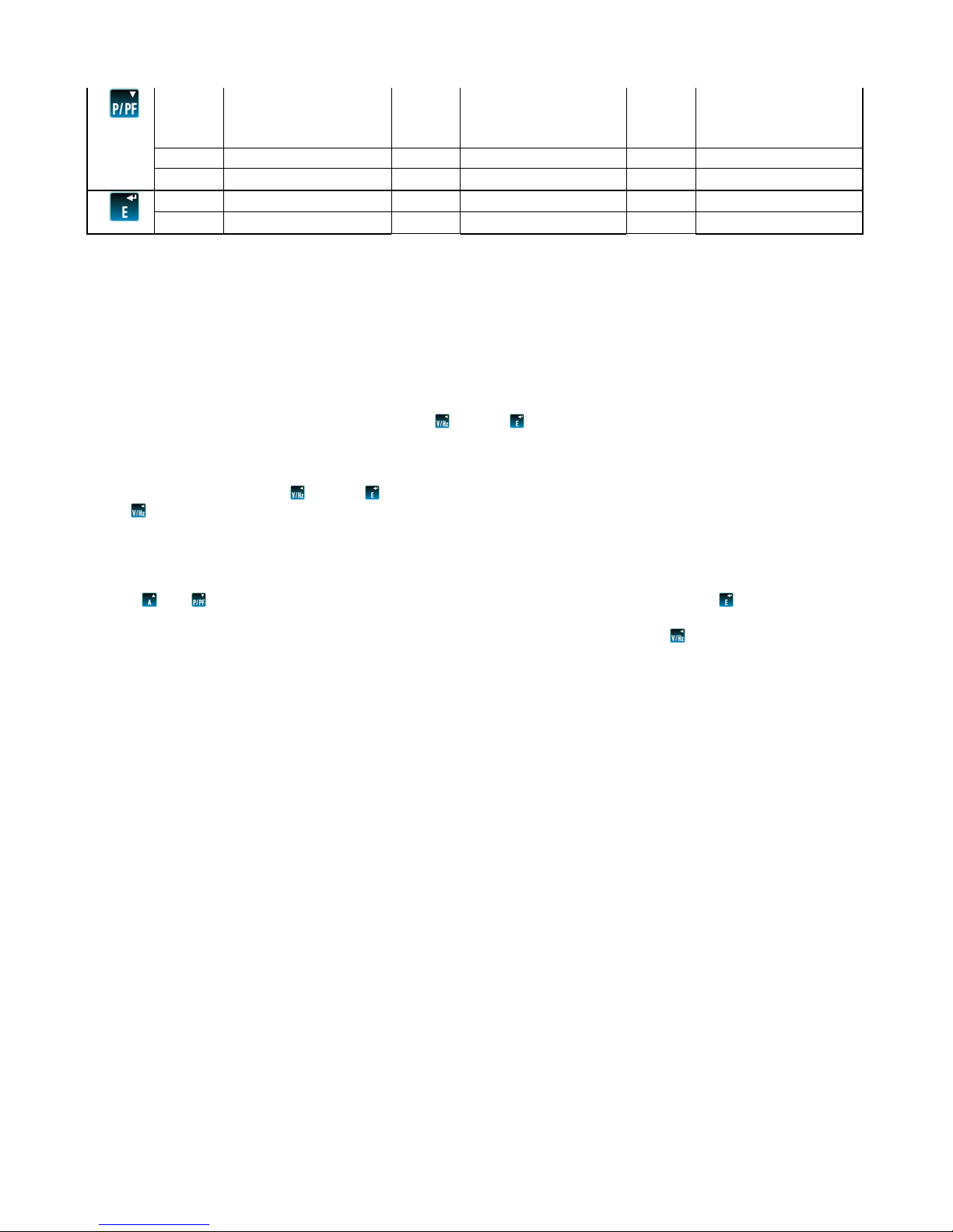
1 kW 1 kW 1 kW
kVAr kVAr kVAr
kVA kVA kVA
2 kW Max Demand 2 kW Max Demand 2 kW Max Demand
3 Power Factor 3 Power Factor 3 Power Factor
1 kWh 1 kWh 1 kWh
2 kVArh 2 kVArh 2 kVArh
3. Set Up
Set up of the Integra Ci3 digital meter may be carried out by using either the local display or the Integra Ci3
digital meter configurator software. The Integra configurator software has its own on-line guide which can be
downloaded from our web-site www.crompton-instruments.com. Additionally, if required, set up parameters may
be manipulated directly via the RS485 communications interface. The following sections give step by step
procedures for configuring the Integra Ci3 digital meter using the front panel.
To access the Set-up screens, press and hold the and the
buttons simultaneously for five seconds. This
displays the password entry screen. Password protection is designed to prevent unauthorised access to Set-up
screens. Password is normally set to 0000 when a product is shipped. When exiting Set-up mode, the
instrument returns to the last selected Display screen. To return to the Display screens at any time during the
set-up procedures, press the and the
buttons simultaneously for five seconds, or keep pressing the back
button . Any set up changes that have already been made will be retained.
3.1 Number Entry Procedure
When configuring the unit, many screens require the entry of a number, usually on the middle row of digits.
For example, on starting the set-up section, a password will be required. The procedure is as follows: press
the
and buttons to change the digit value that is flashing on the screen. Press the button to confirm
the entry and move to the next digit in the sequence. The digits are set one at a time, from left to right until
all four digits are set. At any time during this operation it is possible to press the button to move back to
the previous digit in the sequence.
Project 2187 Drawing No. CI-3K51101 Rev 10
DMR 2720 18/07/11
3
Modbus is a Trademark of Schneider Automation Inc. Other Trademarks or company
names mentioned herein are the property of their respective owners.
Page 4
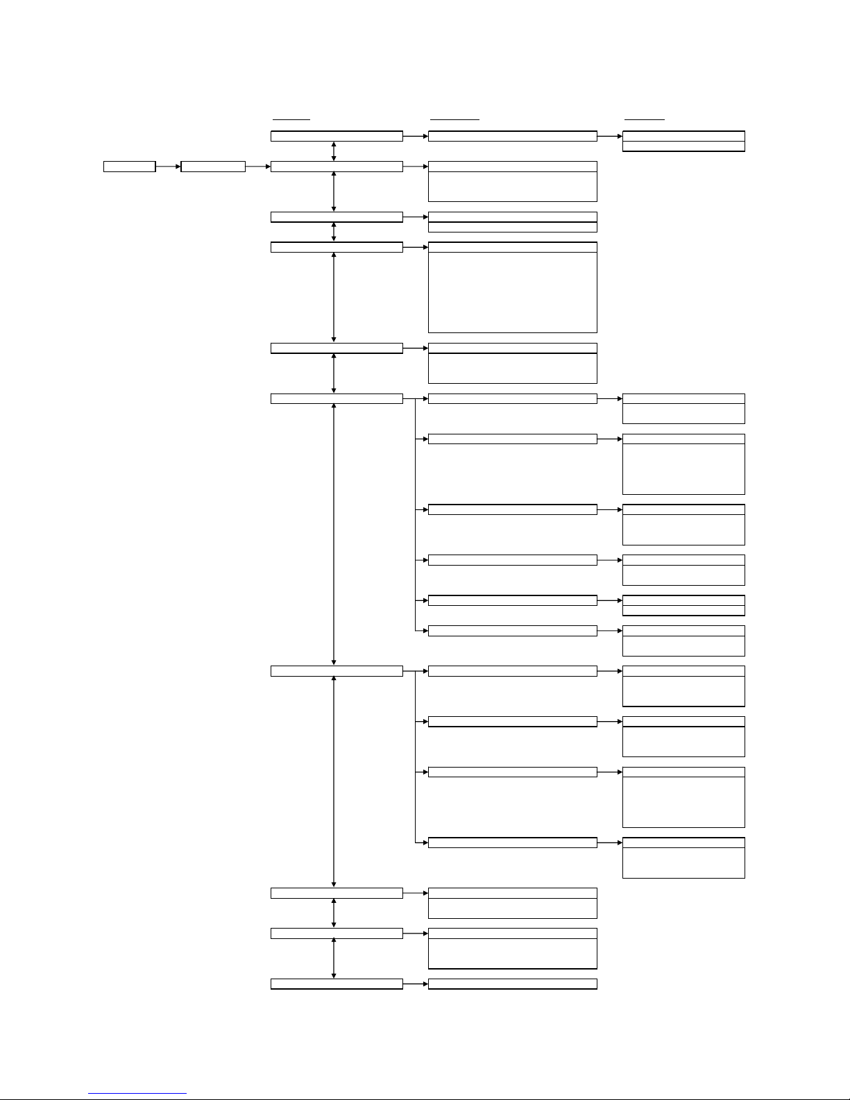
4. Menu Structure
First Level Second Level Third Level
CHNG PASS (Change Password) NPWd (New password) Enter password value between:
Main Screen Password Entry SYS (System Configuration) Select from:
CT (Primary CT) Enter Primary CT Value
dIT (Demand Interval Time) Select from:
RSET (Reset) Select from:
COMS (Communications) PROT (Protocol) Select from:
RLY (Relay) OP1 (Assign Relay Ouput 1) Select from:
NRGY (Energy) Select between:
TEST Select between:
SOFT Displays software version number.
0000-9999
1P2W
3P3W
3P4W
0001-9999 Amps
60 minutes
30 minutes
20 minutes
15 minutes
10 minutes
8 minutes
5 minutes
OFF
ALL (Reset all counters)
hour (Reset kWhr & kVAhr counters)
dMd (Reset demand counters)
Modb (Modbus)
N2 (Johnson Controls)
bAUd (Baud rate) Select from:
PARI (Parity) Select from:
STOP (Stop bits) Select from:
Addr (Address) Enter Address value between:
Ordr (Floating point number byte order) Displays either:
OP2 (Assign Relay Ouput 2) Select from:
RATE (Pulse rate) Select from:
PULS (Pulse Width) Select from:
KILO
MEGA
dISP ON (Tests all display LCD Segments)
dISP TOGL (Toggle LCD display test)
PHAS SEQ (Tests wiring connections)
2400
4800
9600
19200
38400
None
Odd
Even
1
2
1-247
Norm (Normal)
Rev (Reverse)
NONE
KWh (kWhr output)
KVAr (kVAhr output)
NONE
KWh (kWhr output)
KVAr (kVAhr output)
0.1
1
10
100
1000
60mS
100mS
200mS
Project 2187 Drawing No. CI-3K51101 Rev 10
DMR 2720 18/07/11
4
Modbus is a Trademark of Schneider Automation Inc. Other Trademarks or company
names mentioned herein are the property of their respective owners.
Page 5
Menu navigation
Once the correct password has been entered the user can access the first level menu structure. Use the
and
buttons to navigate up and down this level until the desired parameter is reached. Then press the button to
select the desired parameter and enter the second level menu structure. For some parameters such as COMS
there is an additional third level menu structure. Once all the necessary selections have been made and the
required settings entered, press the to return to the first level menu structure.
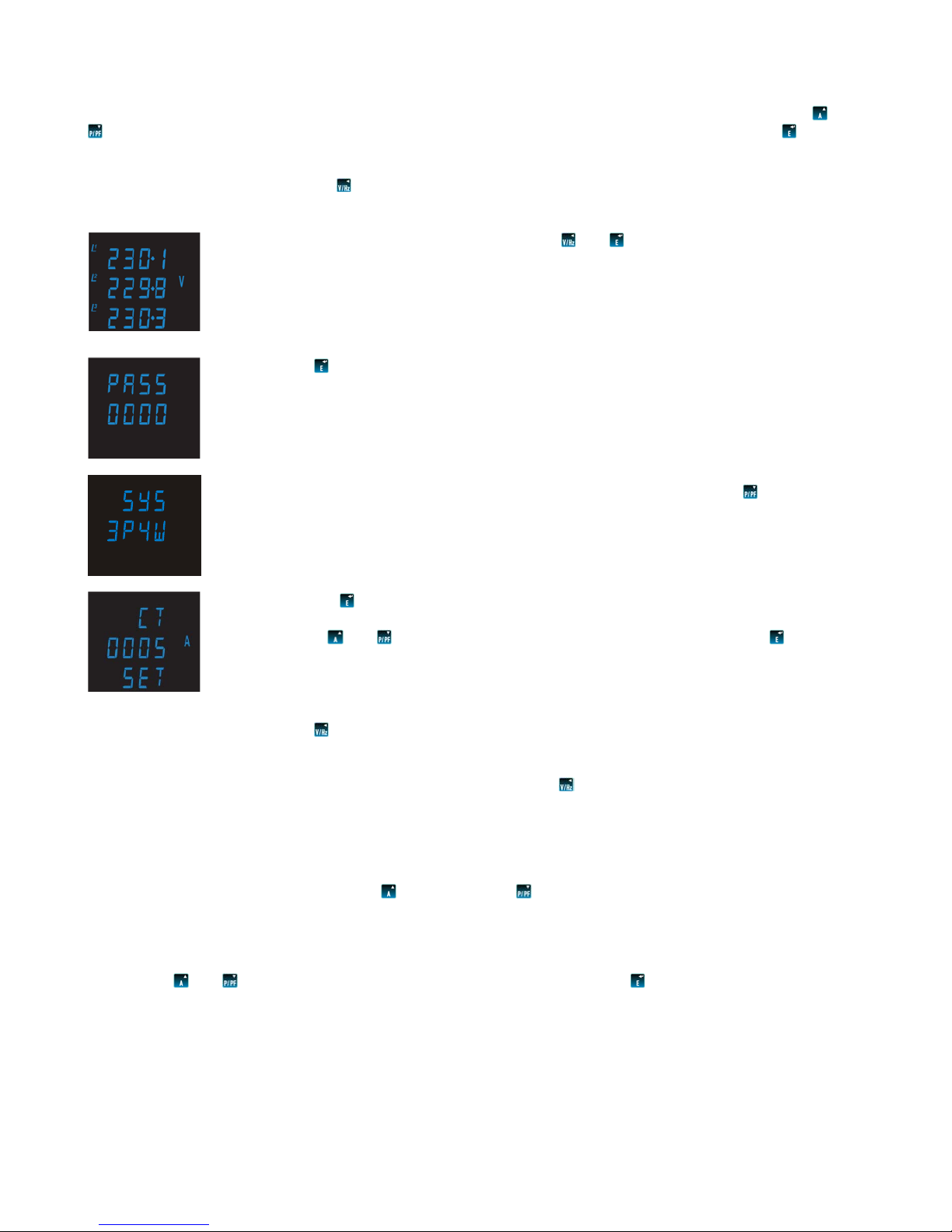
The following example shows how to set the CT primary.
Press and hold the two outermost buttons and
simultaneously for five seconds
until the password screen is displayed.
Press
four times to enter the default password of “0000”.
The system setup screen will be displayed on the screen. Press the
button to scroll
down the menu until you see the CT primary setting screen.
Press the
button to enter the CT primary setting screen. The first digit should start
flashing.
Use the
and buttons to set the digit to the required level then press to confirm.
Repeat this process until all four digits have been set to the desired CT primary value.
(e.g. 100A = 0100A, 1000A = 1000A)
The word “SET” should be displayed after the fourth digit has been entered to confirm
that the primary CT value has been set.
Press to return to the first level menu structure. At this point it is possible to scroll
up and down the first level menu structure so that the user can adjust another
parameter (e.g. system configuration, or comms etc).
If no other setting are required then press to exit set-up mode and return to
measurement mode.
5. Set up screens
You enter the set up screens at 5.2, press
to get to 5.1 and to get to everything else.
5.1 CHNG PASS (Change password)
Selecting this screen takes the user to the new password screen, to enter a new four digit password
between the values of 0000 and 9999.
Use the
and buttons to set the digit to the desired number then press to confirm.
Repeat this process until the desired 4 digit password has been set.
Project 2187 Drawing No. CI-3K51101 Rev 10
DMR 2720 18/07/11
5
Modbus is a Trademark of Schneider Automation Inc. Other Trademarks or company
names mentioned herein are the property of their respective owners.
Page 6

5.2 SYS (System configuration)
This screen is used to set the wiring configuration used for the instrument.
Use the
and buttons to scroll through the following options:
1P2W (Single Phase)
3P3W (3 Phase 3 Wire)
3P4W (3 Phase 4 Wire)
Once the desired system configuration has been found press
to confirm.
5.3 CT (CT Primary)
This screen is used to set the value of the CT primary to be used with the Integra Ci3 digital meter. E.g.
setting this screen to 0100 (100A) will tell the product that a 100/5A CT is being used on the current input
and this value will be used to correctly calculate all Current and Power measurements etc.
Use the
and buttons to set the digit to the desired number then press to confirm.
Repeat this process until the desired CT primary value has been set.
5.4 dIT (Demand Integration Time)
This screen is used to set the period over which the current and power readings are integrated for maximum
demand measurement. The values displayed are in minutes.
Use the
and buttons to scroll through the following options:
60 (60 minutes)
30 (30 minutes)
20 (20 minutes)
15 (15 minutes)
10 (10 minutes)
8 (8 minutes)
5 (5 minutes)
OFF (No demand integration time)
Once the desired demand integration time has been selected, press
to confirm.
5.5 RSET (Reset)
This screen allows Energy and Demand readings to be reset either individually or all together.
Resetting the Energy (hour) sets the kWhr and kVAhr counters to zero.
Resetting the Demand (dMd) sets the Current Demand and Watt Demand counters to zero.
Use the
and buttons to scroll through the following options:
ALL (Reset all counters)
hour (Reset kWh and kVArh counters)
dMd (Reset demand counters)
Once the desired reset has been selected, press
to confirm.
5.6 COMS (Communications)
This screen allows the adjustment of all parameters that are required for the optional communications
module (if fitted). Selecting this screen opens a sub-menu of communication parameters:
5.6.1 PROT (Protocol)
This screen sets the communication protocol for the RS485 port.
Scroll through the following options:
Modb (Modbus protocol)
N2 (Johnson Controls Interface)
Once the desired protocol has been selected press
to confirm.
Project 2187 Drawing No. CI-3K51101 Rev 10
DMR 2720 18/07/11
6
Modbus is a Trademark of Schneider Automation Inc. Other Trademarks or company
names mentioned herein are the property of their respective owners.
Page 7

5.6.2 bAUd (Baud rate)
Scroll through the following options:
2400
4800
9600
19200
38400
Once the desired baud rate has been found press
to confirm.
5.6.3 PARI (Parity)
Scroll through the following options:
None
Odd
Even
Once the required parity has been selected press
to confirm.
5.6.4 STOP (Stop Bits)*
*Note: This function is only enabled if Parity (5.6.3) is set to “None”.
Scroll through the following options:
None
Odd
Even
Once the required stop bits have been selected press
to confirm.
5.6.5 Addr (Device Address)
The instrument will only allow valid Modbus protocol addresses in the range of 1-247 or Johnson
Controls addresses in the range 1-255.
Use the
and buttons to set the digit to the desired number then press to confirm.
Repeat this process until the desired 3 digit address has been set.
5.6.6 Ordr (Floating Point Byte Order)*
This screen displays the floating point number byte order, either Norm (Normal) or Rev (Reverse).
*Note: No adjustment of this parameter is allowed via the front of the Integra Ci3 digital meter. Changes
to the floating point number byte order must be made on the Modbus system; for information on how to
adjust this setting please refer to the Integra Communications Guide, available from our web-sit e.
5.7 RLY (Relay)
This screen allows the adjustment of all parameters that are required for the optional Pulse Relay Module (if
fitted). Selecting this screen opens a sub menu of relay parameters:
5.7.1 OP1 (Relay Output 1)
This screen allows the user to assign Pulse Relay Output 1 to measure either None, kWh or kVArh.
Scroll through the following options:
None (Relay disabled)
KWh (kWh pulsed output)
KVAr (kVArh pulsed output)
Once the required pulsed output setting has been selected press
to confirm.
5.7.2 OP2 (Relay Output 2)
This screen allows the user to assign Pulse Relay Output 2 to measure either None, kWh or kVArh.
Scroll through the following options:
None (Relay disabled)
KWh (kWh pulsed output)
KVAr (kVArh pulsed output)
Once the required pulsed output setting has been selected press
to confirm.
Project 2187 Drawing No. CI-3K51101 Rev 10
DMR 2720 18/07/11
7
Modbus is a Trademark of Schneider Automation Inc. Other Trademarks or company
names mentioned herein are the property of their respective owners.
Page 8

5.7.3 RATE (Pulsed Output Rate)
This screen allows the user to adjust the number of kWh or kVArh’s per output pulse:
Scroll through the following options:
0.1 (1 pulse per 0.1 kWh/kVArh)
1 (1 pulse per 1 kWh/kVArh)
10 (1 pulse per 10 kWh/kVArh)
100 (1 pulse per 100 kWh/kVArh)
1000 (1 pulse per 1000 kWh/kVArh)
Once the desired pulse rate has been selected, press
to confirm.
5.7.4 PULS (Pulse Width)
This screen allows adjustment to the duration of the relay output pulse. Values are displayed in
milliseconds (ms).
Scroll through the following options:
60 (60ms)
100 (100ms)
200 (200ms)
Once the desired pulse rate has been selected, press
to confirm.
5.8 NRGY (Energy)
This screen selects either kWh/kVArh or MWh/MVArh Energy rea ding s.
Scroll through the following options:
KILO
MEGA
Once the desired energy setting has been selected, press
to confirm.
5.9 TEST (Product Self Tests)
This screen allows the selection of a number of self diagnostic test routines.
Scroll through the following options:
dISP ON This test illuminates all the LCD segments to identify any display errors.
dISP TOGL This test toggles on and off alternate halves of the LCD segments, to determine if any
are stuck either on or off.
PHAS SEQ This test determines if the Voltage and Current connection s to the Ci3 meter are correct.
If all the connections are correct the product will display V 123 and I 123. For example,
if the product displayed V 132 and I 123 this would indicate that the Voltage connections
are in reverse sequence and need to be changed.
Once the desired self test has been selected, press
to confirm.
Refer to basis of measurement and calculations for qualifying conditions, 6.7.
5.10 SOFT (Software Version Number)
This screen displays the version number of the software installed in the Integra Ci3 digital mete r.
6. Basis of measurement and calculations
6.1 Phase to Phase voltages
Phase to Phase voltages are measured directly and calculated as RMS values. Situations where the
phases are not spaced 120 degrees apart (e.g. 4 wire open delta) are indicated correctly.
6.2 Reactive and Apparent Power
Active powers are calculated directly by multiplication of voltage and current samples. Reactive powers are
calculated using the frequency corrected quarter phase time delay method. Apparent power is calculated as
the square root of the sum of the squares of active and reactive powers.
6.3 Energy resolution
Cumulative energy counts are reported using the standard IEEE floating point format. Reported energy
values in excess of one million may show a small non cumulative error in the integer digits due to the
Project 2187 Drawing No. CI-3K51101 Rev 10
DMR 2720 18/07/11
8
Modbus is a Trademark of Schneider Automation Inc. Other Trademarks or company
names mentioned herein are the property of their respective owners.
Page 9

limitations of the number format. Internally the count is maintained with greater precision. The reporting
error is less than 1 part per million and is automatically corrected when the count increases.
6.4 Power Factor
The magnitude of Per Phase Power Factor is derived from the per phase active power and p er phase
reactive power. The power factor value sign is set to negative for an inductive load and positive for a
capacitive load.
The magnitude of the System Power Factor is derived from the sum of the per phase active power and per
phase reactive power. Individual phases whose apparent power is less than 3% of nominal are not included
in power factor determinations. The system power factor value sign is set to negative for an inductive load
and positive for a capacitive load. The load type, capacitive or inductive, is determined from the signs of the
sums of the relevant active powers and reactive powers. If both signs are the same, then the load is
inductive, if the signs are different then the load is capacitive. The magnitude of the phase angle is the
ArcCos of the power factor. Its sign is taken as the opposite of the VAr's sign.
6.5 Maximum Demand
The maximum power consumption of an installation is provided as power utilities often levy related charges.
Many utilities use a thermal maximum demand indicator (MDI) to measure this peak power consumption. An
MDI averages the power consumed over a number of minutes, reflecting the thermal load that the demand
places on the supply system. The Integra Ci3 digital meter uses a sliding window algorithm to simulate the
characteristics of a thermal MDI instrument, with the demand period being updated every minute. Demand
Integration Times can be set to Off, 5, 8, 15, 20, 30 or 60 minutes. Maximum Demand is the maximum
power or current demand that has occurred since the unit was last reset. This is maintained as a continuous
record of the highest demand value that has been reached. Note: During the initial period when the “sliding
window” does not yet contain a full set of readings (i.e. the elapsed time since the demands were last reset
or the elapsed time since the Integra Ci3 digital meter was switched on is less than the selected demand
integration time) then maximum demands may not be true due to the absence of immediate historical data.
With the Demand Integration Time set to “Off” the “Maximum Demand” values become “Maximum” values as
no averaging is performed on the measured parameters.
6.6 Total Harmonic Distortion
The calculation used for Total Harmonic Distortion is: THD = ((RMS of total waveform – RMS of
fundamental) / RMS of total waveform) x 100. This is often referred to as THD – R, and lies in the range 0 to
100%. THD measurement is subject to the 'range of use' limits. The Integra Ci3 digital meter may give
erratic or incorrect readings where the THD is very high and the fundamental is essentially absent. For low
signal levels the noise contributions from the signal may represent a significant portion of the “RMS of total
waveform” and may thus generate unexpectedly high values of THD. To avoid indicating large figures of
THD for low signal levels the product will produce a display of 0 (zero). Typically, display of THD will only
produce the 0 (zero) value when the THD calculation has been suppressed du e to a low signal level being
detected. It should also be noted that spurious signals (for example, switching spikes) may be included in
the “RMS of the total waveform” and will be used in the calculation of THD. The display of THD may be
seen to fluctuate under these conditions.
6.7 Phase Sequence Test
The voltage and current inputs must be above 5% of nominal for the test to operate reliably.
In three phase four wire mode the measurements are referenced from L1.
For the voltage sequence test the phase of L2 relative to L1 must be within the window 240 +/- 48 degrees
and L3 relative to L1 must be within the window 120 +/- 48 degrees to record the sequence V123.
Alternatively, the phase of L2 relative to L1 must be within the window 120 +/- 48 degrees and L3 relative to
L1 must be within the window 240 +/- 48 degrees to record the sequence V132.
For the current sequence test the phase of I1 relative to L1 must be within the window 0 +/- 48 degrees, I2
relative to L1 must be within the window 240 +/- 48 degrees, and I3 relative to L1 must be within the window
120 +/- 48 degrees to record the sequence i123.
Project 2187 Drawing No. CI-3K51101 Rev 10
DMR 2720 18/07/11
9
Modbus is a Trademark of Schneider Automation Inc. Other Trademarks or company
names mentioned herein are the property of their respective owners.
Page 10

Alternatively the phase of I1 relative to L1 must be within the window 0 +/- 48 degrees, I2 relative to L1 must
be within the window 120 +/- 48 degrees, and I3 relative to L1 must be within the window 240 +/- 48 degrees
to record the sequence i132.
In three phase three wire mode the measurements are referenced from L1-L2.
For the voltage sequence test the phase of L2-L3 relative to L1-L2 must be within the window 240 +/- 48
degrees and L3-L1 relative to L1-L2 must be within the window 120 +/- 48 degrees to record the sequence
V123.
Alternatively, the phase of L2-L3 relative to L1-L2 must be within the window 120 +/- 48 degrees and L3
relative to L1-L2 must be within the window 240 +/- 48 degrees to record the sequence V132.
For the current sequence test the phase of I1 relative to L1-L2 must be within the window 330 +/- 48
degrees, I2 relative to L1-L2 must be within the window 210 +/- 48 degrees, and I3 relative to L1-L2 must be
within the window 90 +/- 48 degrees to record the sequence i123.
Alternatively, the phase of I1 relative to L1-L2 must be within the window 330 +/- 48 degrees, I2 relative to
L1-L2 must be within the window 90 +/- 48 degrees, and I3 relative to L1-L2 must be within the window 21 0
+/- 48 degrees to record the sequence i132.
The voltage and current inputs must be above 5% of nominal for the test to operate reliably.
7. Installation and Maintenance
Warnings
During normal operation, voltages hazardous to life may be present at some of the terminals of this unit.
Installation and servicing should be performed only by qualified, properly trained personnel abiding by local
regulations. Ensure all supplies are de-energised before attempting connection or other procedures.
Terminals should not be user accessible after installation and external installation provisions must be sufficient
to prevent hazards under fault conditions.
This unit is not intended to function as part of a system providing the sole means of fault protection - good
engineering practice dictates that any critical function be protected by at least two independent and diverse
means.
The unit does not have internal fuses therefore external fuses must be used for protection and safety under
fault conditions.
Never open-circuit the secondary winding of an energized current transformer.
This product should only be operated with CT secondary connections Earthed.
If this equipment is used in a manner not specified by the manufacturer, protection provided by the equipment
may be impaired.
Auxiliary circuits (communication & relay outputs) are separated from metering inputs and 110-400V auxiliary
circuits by at least basic insulation. Such auxiliary circuit terminals are only suitable for connection to
equipment which has no user accessible live parts. The insulation for such auxiliary circuits must be rated for
the highest voltage connected to the instrument and suitable for single fault condition. The connection at the
remote end of such auxiliary circuits should not be accessible in normal use. Depending on application,
equipment connected to auxiliary circuits may vary widely. The choice of connected equipment or combination
of equipment should not diminish the level of user protection specified.
Caution: Risk of Electric Shock
Project 2187 Drawing No. CI-3K51101 Rev 10
DMR 2720 18/07/11
10
Modbus is a Trademark of Schneider Automation Inc. Other Trademarks or company
names mentioned herein are the property of their respective owners.
Page 11

7.1 Checks and Cleaning
The front of the case should be gently wiped with a dry cloth only. Do not apply any pressure over the
central rectangular display viewing window area. If necessary wipe the rear case with a dry cloth. If a
cleaning agent is necessary, isopropyl alcohol is the only recommended agent and should be used
sparingly. Water should not be used. If the rear case exterior or terminals should accidentally be
contaminated with water, the unit must be thoroughly dried before further service. Should it be suspected
that water or other contaminants might have entered the unit, factory inspection and refurbishment is
recommended. In normal use, little maintenance is needed. As appropriate for service conditions, isolate
electrical power, inspect the unit and remove any dust or other foreign material present. Periodically check
all connections for freedom from corrosion and screw tightness, particula rly if vibration is prese nt. The front
display window also acts as an insulating barrier. It is not possible to touch, by hand, any live part, even if
the window is completely missing, but if the window is perforated or significantly damaged in any other way,
repair is required. In the unlikely event of a repair being necessary, it is recommended that the unit be
returned to factory.
7.2 Location and Mounting
Units are suitable for panel mounting only and should be installed in a dry position, where the ambient
temperature is reasonably stable and will not be outside the range -10 to +55°C. Vibration should be kept to
a minimum. Preferably mount the Integra Ci3 digital meter so that the display contrast is not reduced by
direct sunlight or other high intensity lighting. The Integra may be mounted in a standard DIN 96 panel up to
a maximum thickness of 5 mm. Mounting is by four integral retention clips. Terminals should be
inaccessible after installation. Consideration should be given to the space required above and below the
instrument to allow for associated cables. If IP54 ingress protection is required, a panel gasket must be
used. The terminals at the rear of the product must be protected from liquids or other contamination. This
unit is intended for indoor use only at an altitude of less than 2000m.
7.3 Electromagnetic Compatibility
This unit has been designed to provide protection against EM (electro-magnetic) interferen ce in line with EU
requirements and other regulations. Precautions necessary to provide proper operatio n of this, and
adjacent, equipment will be installation dependent and so the following can only be general guidance:
• Avoid routing the wiring to this unit alongside cables and products that are, or could be, a source of
interference.
• The auxiliary supply to the unit should not be subject to excessive interference. In some cases, a supply
line filter may be required.
• To protect the product against incorrect operation or permanent damage, surges and transients must be
controlled. It is good EMC practice to suppress transients and surges at the source. The unit has been
designed to automatically recover from typical transients; however in extreme circumstances it may be
necessary to temporarily disconnect the auxiliary supply for a period of greater than 10 seconds to restore
correct operation.
• Screened communication and small signal leads are recommended and may be required. These and other
connecting leads may require the fitting of RF suppression components such as ferrite absorbers, line filters
etc., if RF fields cause problems.
• It is good practice to install sensitive electronic instruments that are performing critical functions in EMC
enclosures that protect against electrical interference causing a disturbance in function.
7.4 Metered Supply Wiring
Input connections are made to screw clamp terminals. Choice of cable should meet local regulations for the
operating voltage and current. The current inputs of this product are designed for connection into
systems via current transformers only. Instrument transformers used for connection to the meter must be of
approved type and compliant with ANSI/IEEE C57.13 or IEC 60044-1, selected and sized appropriate to the
supply network being monitored. All negative current inputs are commoned inside the unit and grounding should
be at one point only. To minimise measurement errors, the CTs should be grounded as shown in the wiring
diagram. CT secondaries must be grounded in accordance with local regulations. It is desirable to make
Project 2187 Drawing No. CI-3K51101 Rev 10
DMR 2720 18/07/11
11
Modbus is a Trademark of Schneider Automation Inc. Other Trademarks or company
names mentioned herein are the property of their respective owners.
Page 12

provision for shorting links to be made across CTs to permit easy replacement of a unit should this ever be
necessary.
All connections are made to screw clamp terminals. Terminals are suitable for copper wires only and will accept
one stranded 0.05 - 2.5mm
2
(30 - 12AWG) stranded or solid core cables. Instruments are intended for panel
mounting. Terminals must be enclosed within the panel. Use wire rated at 600V for main terminals, 60°C
minimum temperature. Terminal screws are fully tightened for shipment and must be undone before wire
insertion. Terminal screws should be tightened to 0.5 Nm (4.4 lbf in) only.
Additional considerations for three wire systems
The neutral terminal (terminal N) is indirectly connected to the voltage input terminals (terminals L1, L2, L3).
When connected to a three wire system the neutral terminal will adopt a potential somewhere between the
remaining lines. If external wiring is connected to the neutral terminal it must be connected to either the neutral
line or earth (ground) to avoid the possibility of electric shock from the neutral terminal.
Fusing
This unit must be fitted with external fuses in voltage and auxiliary supply lines. Voltage input lines must be
fused with a fast blow fuse 1A maximum. Auxiliary supply lines must be fused with a slow blow fuse rated 1A
maximum (if product is powered line-to-line, ensure both lines are fused). Choose fuses of a type and with a
breaking capacity appropriate to the supply and in accordance with local regulations.
A suitable switch or circuit breaker conforming to the relevant parts of IEC 60947-1 and IEC 60947-3 should be
included in the installation. It should be positioned so as to be easy to operate, in close proximity to the
equipment, and clearly identified as the disconnecting device.
Earth/Ground Connections
For safety reasons, current transformer secondary connections should be grounded in accordance with local
regulations. Under no circumstances should the product be operated without this Earth connection.
8. Auxiliary and Output Connections
8.1 Auxiliary Supply
The auxiliary supply is rated at 100-400V AC ± 10%, 120-350 DC ±20%. The Integra Ci3 digital meter
should ideally be powered from a dedicated supply, however it may be powered from the signal source
providing the source remains within tolerance of the auxiliary supply voltage range.
8.2 Output Connections
8.2.1 RS485 module Option
The recommended cable between the RS485 master and the Integra Ci3 digital meter is two core
screened cable. Preferably select a cable specifically recommended for RS485 use (for example Belden
9860, 8761) although for shorter distances of a few metres most two core screened cables will usually
be satisfactory. Cable length (transmission distance) can be up to 1200 metres in good conditions.
Electrical interference or other adverse conditions may reduce the maximum cable length possible.
8.2.2 Pulse Relay Module Option
Up to 2 solid state relays can be fitted, if there is no RS485 module fitted. Relay rating is 250V, 50mA,
maximum. Lines connected to these terminals must be either short in length or filtered where
appropriate.
Project 2187 Drawing No. CI-3K51101 Rev 10
DMR 2720 18/07/11
12
Modbus is a Trademark of Schneider Automation Inc. Other Trademarks or company
names mentioned herein are the property of their respective owners.
Page 13

8.3 Connection Diagrams
Note: 11, 12, and 13 negative terminals are commoned within the instrument.
9. Specification
Measurement Inputs
Imported energies are recorded.
Three current inputs (six physical terminals) with 2·5mm2 stranded wire capacity for connection of external CTs.
Voltage inputs through 4-way fixed connector with 2·5mm
2-wire unbalanced. Line frequency measured from L1 voltage or L3 voltage.
2
stranded wire capacity. 3-Phase 3- and 4-wire and Single-phas e
Ci3-01
Direct measurement of 173 to 500Vac L-L (100 to 289Vac L-N).
Ci3-VT
System voltage is entered as "Potential Transformer Prim ary Voltage", which has limits determined by the s ystem type:
104 volts to 34·5 kilovolts L-L (60 volts to 20 kilovolts L-N).
This value is entered with four digit resolution.
The nominal voltage presented to the product terminals when the potential transformer primary is supplied with the
"system voltage" defined above is entered as the "Potential Transformer Secondary Voltage", which has limits determined
by the system type: 104 volts to 208 volts L-L (60 volts to 120 volts L-N).
This value is entered with three digit resolution.
Range of Use
Values of measured quantities, components of measured quantities, and quantities which affect measurement errors to some
Degree, for which the product gives meaningful readings:
Voltage (Ci3-01)
Voltage (Ci3-VT)
Current
Active power
Apparent power
5 … 120% of Range Maximum
(below 5% of Range Maximum voltage, current indication may only be approximate)
5% of Range Maximum to 120% of Potential Transformer secondary voltage
(below 5% of Range Maximum voltage, current indication may only be approximate)
1 … 120% of nominal
1 … 144% of nominal, 360MW maximum
1 … 144% of nominal, 360MVA maximum
Power is only registered when voltage when voltage and current are within their respective range of use.
Project 2187 Drawing No. CI-3K51101 Rev 10
DMR 2720 18/07/11
13
Modbus is a Trademark of Schneider Automation Inc. Other Trademarks or company
names mentioned herein are the property of their respective owners.
Page 14

Input
Nominal Input voltage
CI3-01 100 to 289V AC L-N (173 to 500V AC L-L)
CI3-VT 60 to 120V AC L-N (104 to 208V AC L-L)
Max. continuous input overload voltage 120% of nominal (Maximum 600V AC L-L)
Max. short duration input voltage 2 x range maximum (1 second application repeated 5 times at 5
minute intervals)
Nominal input voltage burden < 0.2VA per phase
Nominal input current 5A AC rms
Max. continuous input overload current 120% of nominal
Max. short duration input current 10 x nominal (1 second application repeated 5 times at 5
minute intervals)
Frequency 45 to 66Hz
Burden 5VA nominal
Auxiliary
Operating range 110 to 400V AC nominal ±10% (99-440V AC absolute limits)
120 to 350V DC nominal ±20% (96-420V DC absolute limits)
Accuracy
Voltage (V) 0.5% of range maximum
Current (A) 0.5% of range maximum (4% for I2 in three wire mode)
Neutral current calculated (A) 4% of range maximum
Frequency (Hz) 0.1 Hz
Power factor (PF) 1% of unity
Active power (W) ± 1% of range maximum
Reactive power (VAr) ± 1% of range maximum
Apparent power (VA) ± 1% of range maximum
Active energy (kWh) Class 1 (IEC 62053-21)
Reactive energy (kVArh) ± 1% of range maximum
THD 1% up to 31
st
harmonic
Response time to step input 1s typical to >99% of final value
Output modules (optional)
Pulsed output relays 1 per module
(maximum of 2 modules fitted per Integra Ci3 digital meter)
Contact rating 50mA max at 250V AC
Type Solid state relay
RS485 output module 1 channel per module
(maximum of 1 module fitted per Integra Ci3 digital meter)
Type 2-wire half duplex
Baud rate 2400, 4800, 9600, 19200, 38400
Enclosure
Style DIN 96 panel mount
Dimensions 96x96x64.1mm (depth behind panel front without module
58mm, with module 82.5mm)
Panel cut-out 92x92mm
Panel thickness 1 to 5mm
Front protection rating IP52
Case protection rating IP30
Material Polycarbonate to UL94V0
Weight 300g
Terminals Shrouded screw-clamp 0.05 to 2.5mm
2
wire
Tighten to 0.5 Nm (4.4 lbf in)
Project 2187 Drawing No. CI-3K51101 Rev 10
DMR 2720 18/07/11
14
Modbus is a Trademark of Schneider Automation Inc. Other Trademarks or company
names mentioned herein are the property of their respective owners.
Page 15

Environmental
Operating temperature -10°C to +55°C
Storage temperature -20°C to +70°C
Relative humidity 0 to 90% non-condensing
Shock 30g in 3 planes
Vibration 10Hz to 50Hz, IEC 60068-2-6, 2g
Dielectric voltage Withstand test 2.2kV rms 50Hz for 1 minute between Measuring Voltage
Inputs to RS485 and Relay, and between Auxiliary to RS485
and Relay.
10. Dimensions
11. Panel cut-out
Project 2187 Drawing No. CI-3K51101 Rev 10
DMR 2720 18/07/11
15
Modbus is a Trademark of Schneider Automation Inc. Other Trademarks or company
names mentioned herein are the property of their respective owners.
Page 16

12. Graphical Symbols and Warnings
The following symbols may appear in this user guide, and may also be affixed to the products discussed in this
guide:
Symbol Description
Earth connection
Caution, Risk of electric shock
Caution, Refer to accompanying text
Tyco Electronics UK Ltd.
Energy Division
Freebournes Road, Witham
CM8 3AH, Essex, UK
Tel: +44 (0)870 870 7500
Fax: + 44 (0) 870 240 5287
www.crompton-instruments.com
Project 2187 Drawing No. CI-3K51101 Rev 10
DMR 2720 18/07/11
While Tyco Electronics and its affiliates referenced herein have made every reasonable effort to ensure the accuracy of the
information contained in these instructions, Tyco Electronics cannot assure that this information is error free. For this reason,
Tyco Electronics does not make any representation or offer any guarantee that such information is accurate, correct, reliable,
or current. Tyco Electronics reserves the right to make any adjustments to the information at any time. Tyco Electronics
expressly disclaims any implied warranty regarding the information contained herein, including, but not limited to, the implied
warranties of merchantability or fitness for a particular purpose. Tyco Electronics' only obligations are those stated in Tyco
Electronics’ Standard Terms and Conditions of Sale. Tyco Electronics will in no case be liable for any incidental, indirect or
consequential damages arising from or in connection with, including, but not limited to, the sale, resale, use, or misuse of its
products. Users should rely on their own judgement to evaluate the suitability of a product for a certain purpose and test each
product for its intended application.
TE (logo) and Tyco Electronics are trademarks of the Tyco Electronics group of companies and its licensors. Crompton is a
trademark of Crompton Parkinson and is used by Tyco Electronics under licence. Other Trademarks mentioned herein are
the property of their respective owners.
16
Modbus is a Trademark of Schneider Automation Inc. Other Trademarks or company
names mentioned herein are the property of their respective owners.
 Loading...