

Tyco Electronics FIST-GCO2 Series, GCO2-BC6 Series, GCO2-BE6 Series, GCO2-BD6 Series, GCO2-BC16 Series Installation Instruction
...Page 1

FIST-GCO2
INSTALLATION INSTRUCTION
GCO2-BC6/16-XX
GCO2-BD6/16-XX
GCO2-BE6/16-XX
1 Introduction
2 General
2.1 Abbreviation
2.2 Kit Contents
2.3 Elements needed from the FIST
installation kit
2.4 Tools
2.5 Cable preparation table
3 Installation
3.1 Installation of workstand
3.2 Opening the FIST GCO
4 Cable preparation
4.1 Loose buffer tube cable
4.1a Looped cable preparation
4.1b Bracket/strength member
4.1c Loose buffer tube storage
4.1d Fiber storage in trays
4.1e Drop cable preparation
(6 port base)
4.1f Drop cable preparation
(16 port base) single fiber,
ribbon and compact sheet
cable
4.1g Tube preparation
4.2 Central core cable
4.2a Looped cable preparation
4.2b Bracket/strength member
4.2c Mass storage facility and twisted
fibers:(Using Basket)
4.2d Twistfree fibers
4.2e Drop cable preparation (6 port base)
4.2f Drop cable preparation (16 port base)
5 Heatshrink installation
6 Fiber routing
7 Fiber routing on tray
8 Tube holder capacity
9 Cable grounding / shielding
10 Closing the closure
11 Important steps
12 Re-arrangement
Content
1 Introduction
The generic closure FIST-GCO is the environmentally sealed enclosure for the fiber management system that
provides the functions of splicing and passive component integration in the external network. The product can
be tailored to almost any required configuration by adding splicing and/or passive device Sub-Assemblies. The
FIST-GCO has provision for all cable termination and sealing requirements.
To clean FIST components, the use of isopropylalcohol is recommended.
The closure is a single-ended design made of a thermoplastic material.
The base and dome are sealed with a clamp and an O-ring system. One oval entry port for looped (uncut) cable
management and six or sixteen round ports for single cable entry/exit are included in the base. The cable seals
are manufactured from heat-shrinkable material. The Universal Mounting System provides the foundation for
mounting SOSAs and SASAs back to back. The two back to back sides have each a standard capacity of
28, 42 or 58 units. Uncut loose buffer tube storage is available between the two UMS-sides (Universal Mounting
System). Storage of uncut looped ribbons or fibers from central core (or slotted core) cables is available with the
fiber storage basket. Storage of uncut looped ribbons or fibers can be done in individual FIST-trays.
Page 2
2
Dimensions (in mm)
Closure Type GCO2-BC6-XX GCO2-BD6-XX GCO2-BE6-XX
L 488 566 700
D with clamp 285 285 285
Closure Type GCO2-BC6-XX GCO2-BD6-XX GCO2-BE6-XX
Capacity
Primary coated fibers
Single element 336 480 672*
Single circuit 2 112 160 224
Single circuit 4 224 320 448
Ribbon 4
2 ribbons each tray 40 (160 fibercount) 80 (320) 110 (440)
1 ribbon each tray 20 (80 fibercount) 40 (320) 55 (220)
Ribbon 12
1 ribbon each tray 16 (192 fibercount) 28 (336) 36 (432)
* Capacity on FAS can depend on capacity on tubeholder, see for instance the
capacity table for loose tubes later on
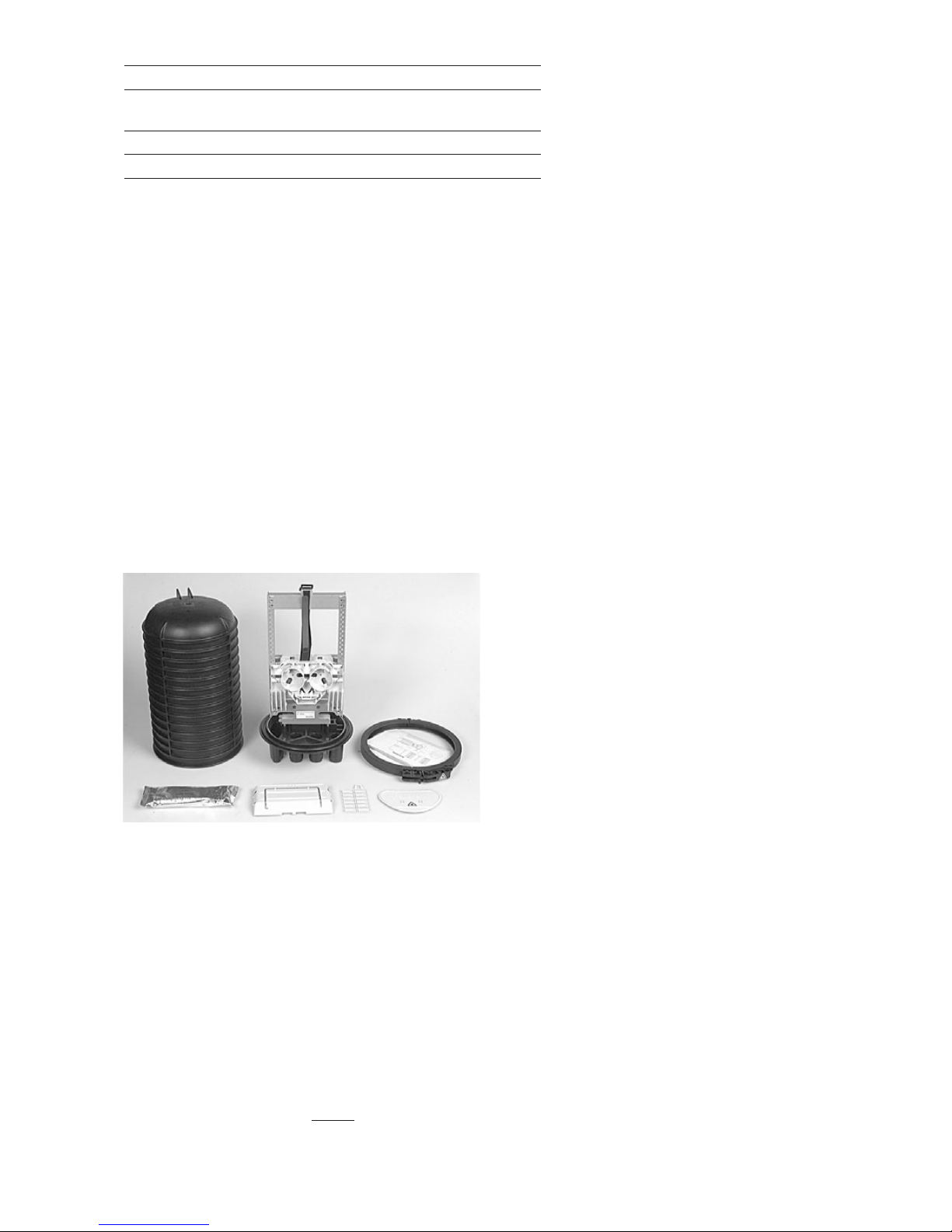
According network layout and cable constructions the kit content can
be different from the kit content described in this installation
instruction.
• Dome
• Base including routing block + cover (universal mounting system),
shield mounting bolt, and strength member termination bracket
• Clamp
• O-ring
• 100g Silicagel
• 2 tray covers + fiber guiding pin +tube holder retainers
• 2 tray wedges
• Installation Instruction
2 General
2.1 Abbreviations
Looped Cable Installation Tool LCIT
Universal Mounting System UMS
2.2 Kit contents
Cable diameters in 6 port base
Loose tube loop, 12-25mm drop,(5-30mm)
C.Core loop, 12-25mm drop,(5-25mm)
Cable diameters in 16 port base
Loose tube loop, 12-25mm drop ports 3-10,(5-20mm)
drop ports 11-18,(5-14mm)
C.Core loop, 12-25mm drop ports 3-10,(5-20mm)
drop ports 11-18,(5-14mm)
Page 3
3
2.3 Elements possibly needed from the FIST installation kit
Product Name UOM QTY/UOM Product description
FISTV-E7185-3010 1 RL 50 m Cut wire to open the FIST-GCO ports
FISTV-E7100-1005 1 PK 10x100g Silicagel for inside the closure, to be replaced after each re-entry
FISTV-SPLI-COL 1 PK 30 sets Split identifications collet (2-sizes) till 3.5mm
2.4 Tools
• FIST-LCIT Looped tube insertion tool for oval outlet To insert loose tubes in oval port
• FACC-TUBE-CUTTER-01 Tube cutter To cut spiral tubing
• FACC-TUBE-STRIPPER-02 Tube stripper To strip loose tubes
• FACC-AXIAL-STRIPPER-01 Tube splitter To split buffer tubes 2.0-3.1mm
• FACC-HEAT-GUN-220V Heatgun + Heatgun tip To shrink cable seals
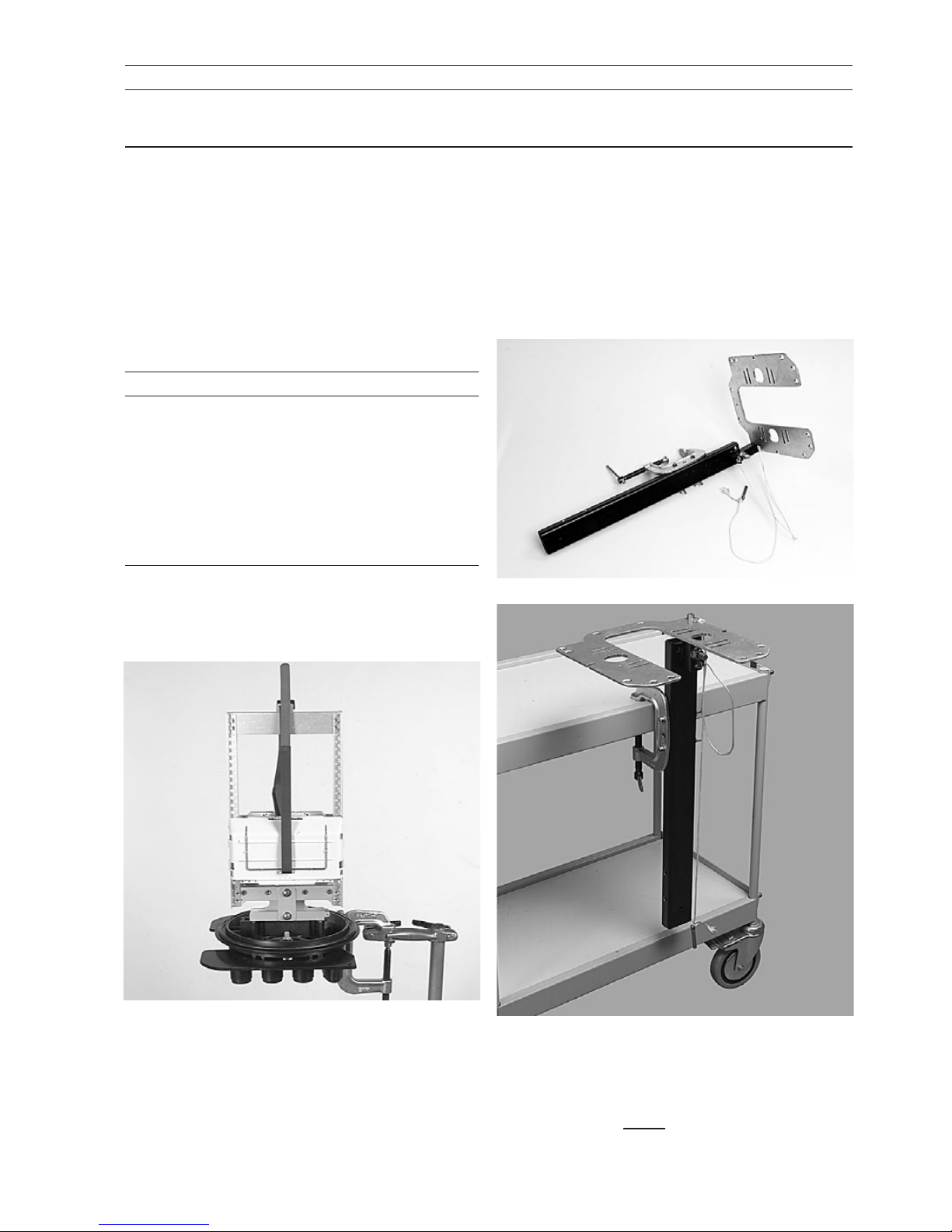
• FIST-WORK-STAND To hold the closure in a vertical position during installation
• FIST-WORK-STAND-H Hinging workstand To hold the closure in any position during installation
3.1.1 The FIST-GCO will be mounted temporary on the work-stand.
The work-stand is wrap-around, so that the FIST-GCO installed with
cables can be taken away from it.
Fix the FIST-GCO base onto the workstand with the four split-pen.
3 Installation
3.1 Installation of workstand
2.5 Cable preparation table
Window cut drop cable
Loose Tube BC6 or 16 3.5 m 2.2 m
BD6 or 16 3.7 m 2.2 m
BE6 or 16 3.9 m 2.2 m
Twisted C.Core BC6 or 16 5.3 m 2.2 m
(Use Basket) BD6 or 16 5.9 m 2.2 m
BE6 or 16 6.1 m 2.2 m
Untwisted C.Core BC6 or 16 3.5 m 2.2 m
BD6 or 16 3.7 m 2.2 m
BE6 or 16 3.9 m 2.2m
3.1.2 The hingable work stand can be used. It is recommended
when he 16 port base is applied.
Page 4
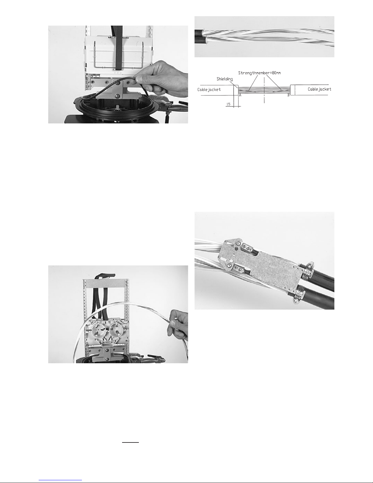
4.1.7 Insert the strength members of the cable into the universal
strength member connector on the loop bracket (loosen the bolts with
the Allen key if necessary) such that all loose tubes can be routed
without unnecessary crossings. Avoid to twist the loop in the case of a
reversed oscillating cable. Fasten with the Allen key.
4.1b Bracket/ Strength member and cable termination
preparation
4
3.2 Opening the FIST-GCO
4 Single fiber
4.1 Loose buffer tube cable
4.1a Looped cable preparation
4.1.1. S-cable: A window cut of 3m50 is needed for GCO2-BC6-XX,
3m70 for GCO2-BD6-XX and 3m90 for GCO2-BE6-XX.
4.1.2 S-cable: Mark the cable in the middle and mark the cable on
(1.75), (1.85) or (1.95) meters left and right of the first mark. Remove
the cable jacket starting in the middle.
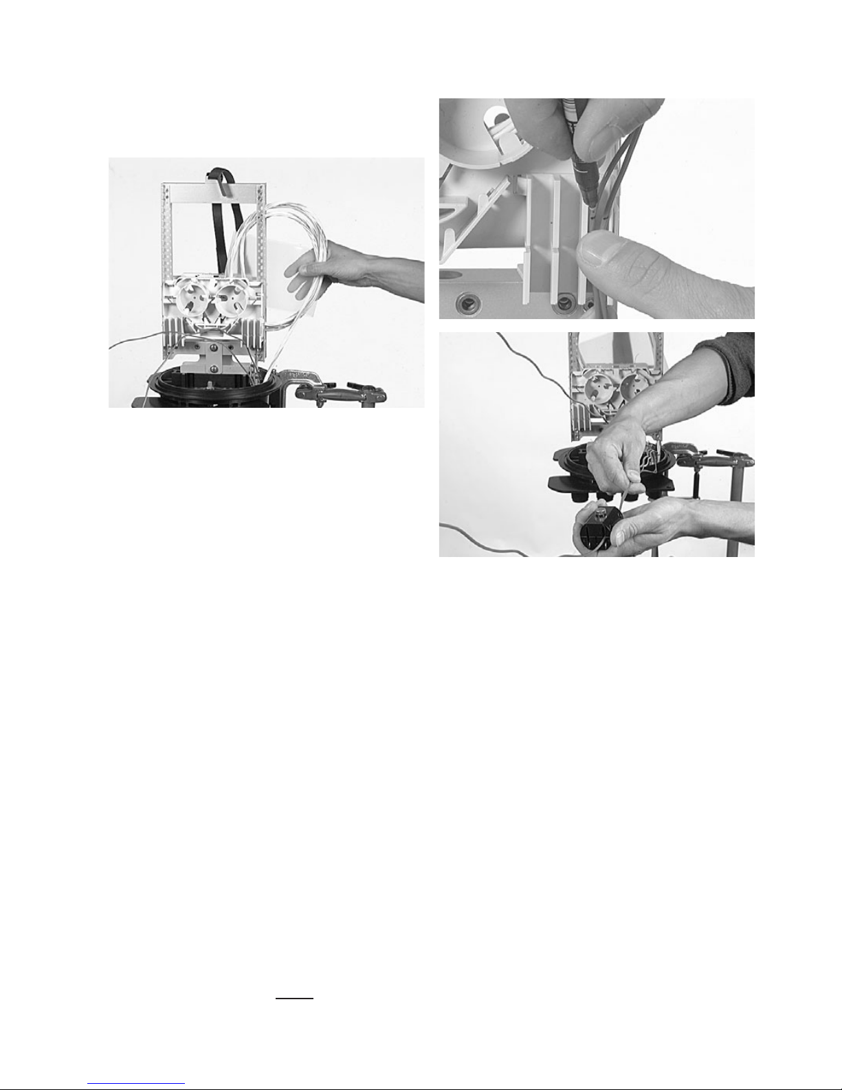
3.2.1 Open and remove the clamp. Remove the dome and the O-ring
Remark: take care with the O-ring and the sealing surfaces on the base
and dome (avoid damaging). Clean only with clear water or with the
cleaning tissue, included in the kit, if needed
4.1.3 Reversed Oscillating cable: Mark the cable in the middle of the
loop and remove cable jacket left and right of the mark over a total
distance of 110cm (little more as the distance between two reversal
points on the cable). Locate the buffer tube reversal point on the cable
and mark the cable on (1.75), (1.85) or (1.95) meters left and right
from this point. Remove further the cable jacket starting from this
point.
Important: make sure that twist position of loose tube is identical in A
and B. This must be done correctly for ease of installation.
4.1.4 Remove the strength member leaving 80mm from the cable
jacket, if shield present leave 15mm of the shield
4.1.5 Clean the loose tubes, remove all grease.
4.1.6 Identify the loose tubes with the split collet rings markers if
necessary. There are different FIST-split-collet-rings depending on
diameter of the loose tube.
A
B
Page 5
5
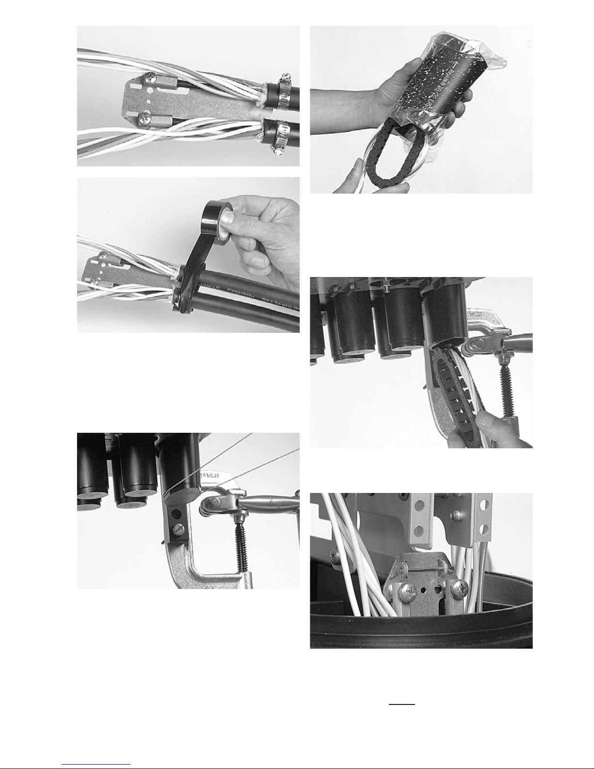
4.1.9 Open the oval port; the cutting wire can be used.
4.1.8 If the cable diameter is more than 8mm Fix the cables with the
hose clamp onto the loop bracket. Wrap a few layers of tape around
the hose clamp.
If the cable diameter is less than 8mm fix the cables with tie wraps.
• When using cables with a diameter smaller than 12mm,bend the
sharp edges on the bottom of the bracket towards the cable and use
some tape around the bracket to protect the heatshrink.
4.1.10 Take the oval sleeve and place the packing bag that has been
opened on both sides in the oval sleeve to prevent the hotmelt inside
the sleeve from dirt and grease. Take the LCIT and bend the loose
tubes gently over it. Push the loose tubes in the sleeve. The non-coated
edge of the sleeve and the arrows should be pointed to the base of the
closure.
4.1.11 Now push the loose tubes (looped around the LCIT) in the oval
port up to the bottom of the bottom bracket.
4.1.12 Remove the LCIT and pull the cable gently in the closure.
Page 6
6
4.1.13 Position the loop bracket in the bottom bracket and lock with
the split pin.
4.1.14 Install heatshrink.
4.1c Loose buffer tube storage
4.1d Fiber storage in trays
4.1.15 Select the loose tube(s) with the fibers that have to be spliced.
4.1.15 Make some loops with the uncut loose tubes, and put these in
the plastic bag (Be careful not to damage the loose tubes!).Two sizes of
bags are available. Use the correct size according the volume of the
loose tubes.
Slide the bag between the UMS. If the capacity of the looped loose
tubes is too much, one puts the loops at one side; in this case fix the
plastic bag with the tubes on the UMS-profiles with tie-wraps. In case
of S-cable cut the loose tube(s) in the middle of the loop for routing
them to the tube holder.
Remark: Loose tubes routed up to the tube holder should be
routed in such a way that one still has complete access of the
stored tubes between UMS profile. This is needed for later
routing of loose tubes from the loops to the tube holders,
without creating crossings and without creating disturbances
on the loose tubes already routed up to the tube holders.
4.1.16 In case of reversed oscillating cable: separate the loose tube(s).
Match the loose tube(s) on the tubeholder and mark both sides
between the two marks. Shave between the two marks with the
appropriate tooling. Clean the fibers and wind some Teflon around the
ends of the tubes and fibers ,to protect the transition from tube to
fibers.
In case of S-cable: cut the loose tube(s) (with fibers that have to be
spliced) in the middle of the loop. Separate the cut loose tube(s) from
the others. Match the loose tube(s) on the tubeholder and mark both
sides. Strip the loose tube(s). Clean the fibers.
- Separate the fibers till the tubeholder and route to single circuit or
single element tray(s).
Page 7
7
4.1.18 In case of Reversed oscillating cable Identify exchange and
customer-side using some Teflon tape around the fibers. One can also
use the FIST-split-collets-rings markers to identify the loose tubes.
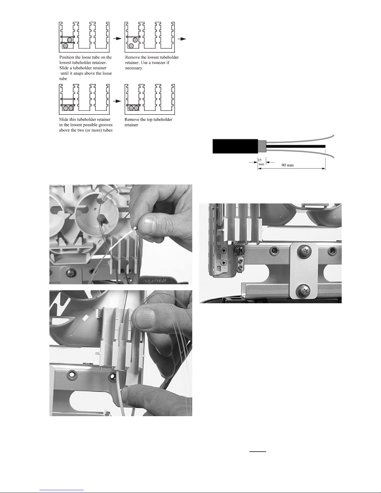
4.1.17 Different loops can be put together beneath the same tube
holder retainer. Position one or more loose tubes in the tubeholder and
slide the tube holder retainer with the snap forward in the lowest
possible cavities of the tubeholder above the loose tube(s). The tube
holder retainer must snap.
4.1.19 - If the fibers are ‘twist free’ one can route the fibers separate
to single circuit trays or single element trays. Separate all fiber loops
first till the tubeholder.
If the fibers are not ‘twist free’ select first the fiber(s) that have to be
spliced and cut these fibers in the middle of the loop. Remove these out
of the bundle till the tubeholder. These fibers can be routed to single
circuit trays, others uncut will be routed to a single element tray (never
in dark fiber storage) (See at fiber routing).
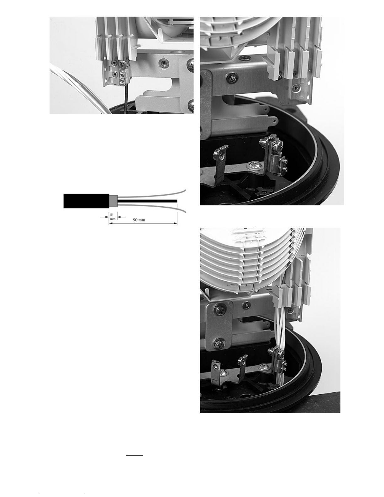
4.1.22 Remove the strength member leaving 90mm from the cable
jacket, if shield present leave 15mm of the shield.
4.1.23 Fix the strength member connector in the closure (on the
bottom bracket )
4.1.24 Take the sleeve and place the packing bag that has been
opened on both sides in the sleeve to prevent the hot melt inside the
sleeve from dirt and grease.. Push the loose tubes in the sleeves. The
non-coated edge of the sleeve and the arrows should be pointed to the
base of the closure (see installation heatshrink).
4.1e Drop cable preparation (6 port base)
4.1.20 Open the round port; the cutting wire can be used
4.1.21 Remove the cable jacket for 2.2m.
Page 8
8
4.1.28 Fix the strength member connector in the closure.
4.1.27 If ports 3-4-5-6-7-8-9-10 are used, cut strength member at 75
mm length. If ports 11-12-13-14-15-16-17 and 18 are used, cut
strength member at 90mm length.
4.1.25 Push the loose tubes in the port and fix the strength member in
the strength member connector. Be sure that all loose tubes are routed
without crossing around the strength member.
4.1f Drop cable preparation (16 port base)
4.1.26 Remove the cable jacket for 2.2m.
4.1.29 Fix the cable in it.
4.1.30 Install the heat shrink.
Page 9

9
4.1.31 Match the loose tube on the tubeholder, mark and strip the
loose tube from this mark. Clean the fibers.
4.1.32 Position one or more loose tubes in the tubeholder according
to the correct position and slide the tube holder retainer with the snap
forward in the lowest possible cavity of the tubeholder above the loose
tube. The tube holder retainer must snap. (see capacity of tubeholders).
4.2 Central Core cable (Single Fiber), ribbon and compact
sheet cable
4.2a Looped cable preparation
4.2.1 Twisted fibers: fibers have to be routed over the BASKET :a
window cut of 5m30 is needed for GCO2-BC6-XX, 5m90 for
GCO2-BD6-XX and 6m10 for GCO2-BE6-XX. Mark the cable in the
middle, and mark the cable on (2.65), (2.95) or (3.05) meters left and
right of the first mark. Remove the cable jacket and the strength
members starting in the middle. For non cut loop storage contact Tyco
Electronics to check if possible
Twistfree fibers or limited twist: direct to tubeholder; a window
cut of 3m50 is needed for GCO2-BC6-XX, 3m70 for GCO2-BD6-XX
and 3m90 for GCO2-BE6-XX. Mark the cable in the middle, and mark
the cable on (1.75),(1.85) or (1.95) meters left and right of the first
mark. Remove the cable jacket and the strength members starting in
the middle.
4.2.3 Remove the jacket for 45mm leaving the strength members.
Be cautious not to damage the strength members.
4.2.4 Remove the central core leaving 20mm from the cable jacket.
Be careful not to loose the ID of the fibers.
In case of metal shield, remove 5 mm from the end.
4.2.5 Clean the fibers.
4.2b Bracket/ Strength member and cable termination
preparation
4.2.6 Slightly loosen the screws of the two strength member stops
on the loopbracket such that one can position the strength members
stops according to the position of the strength members.
4.1g Tube preparation 4.2.2 Mass storage facility: mount the basket (see Basket instruction.
Page 10
10
4.2.7 Insert the strength members from the cable into the strength
member stop. In case cable diameter is more than 8mm, Fix the cable
with the hose clamp onto the loopbracket. In case cable diameter is
less than 8mm. Fix the cable with tie wrap onto the loopbracket Fix the
screw of the strength member stop on the loopbracket. Wind a few
layers of tape around the hose clamp.
When using cables with a diameter smaller than 12mm,bend
the sharp edges on the bottom of the bracket towards the
cable and use some tape around the bracket to protect the
heatshrink.
4.2.9 Place the heatshrink and loop bracket in place as described in
loose tube installation.
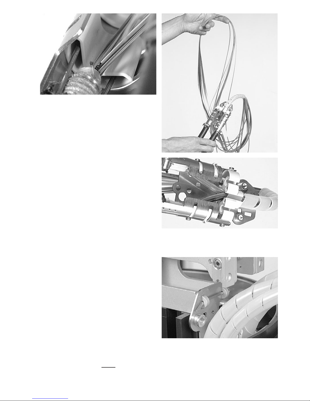
4.2.8 Take the spiral tube and cut it at 160mm length.
Put the tube over the bundle fibers and insert this in the central cavity
of the loop breakout device.
Page 11
11
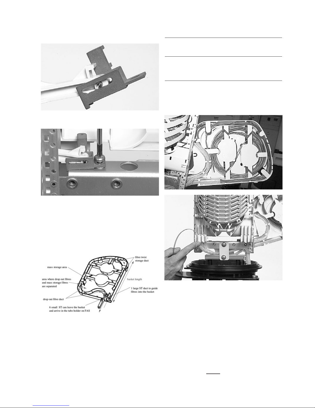
4.2.11 Install hinge on basket with pen.
4.2c Mass storage facility and twisted fibers: Using Basket
(single fiber, ribbon and compact cable sheet)
4.2.10 Start with mounting the basket.
4.2.12 Mount hinge on GCO.
4.2.13 Remove the cover by pulling it at the top of the basket (via the
opening). When the top of the cover clicks out of the snaps shove the
cover upward in the basket till it releases.
ST=Spiral tubing
4.2.16 All fibers are placed in the “fiber twist storage duct” as shown
on the figure above. One has to place the fibers as far as
possible at the outside of the path because when closing the
basket some overlength will be pulled out of the basket (risk of loading
fibers when basket is hinged).
4.2.17 At the point of separation, mass storage fibers and fibers to
drop out are separated. This is possible because all cable-twists are
stored in the “fiber twist storage duct”.
4.2.18 The fibers for mass storage are organised in the mass storage
area of the basket, the loop end is placed over one of the islands.
4.2.14 A large ST is wrapped around the twisted fiber bundle and
fixed in the loop bracket in the oval port. The length of the large ST is
given for each application.: 16 cm for loopbracket cc. In the table
below the capacities of this ST are given.
Fiber type Number of cut Numbers of looped
fibers/ribbons fibers/ribbons
in ST 15 OD in ST 15 OS
SF 392+ 196+
R12 36 18
R8 48 24
R4 100 50
4.2.15 This large ST is placed in the right cavity of the basket by
bending the spiral tube and gliding it in its cavity when the basket is in
an almost closed position.
Page 12

12
4.2.19 The fibers that need to be guided to the routing block are
wrapped with a small ST with a length of 37 cm. Make sure you group
the fibers/ribbon going to the OS1 or ES2-side of a closure separately.
Place as many fibers as possible fibers together in one ST to maintain a
high drop out capacity of your basket (see table below). (The addition
of fibers in an occupied ST is not possible without removal of the ST,
causing transients in the optical fibers).
Fiber type Number of cut Numbers of looped
fibers/ribbons fibers/ribbons
in ST 6 OD in ST 6 OS
SF 70 35
R12 6 3
R8 9 4
R4 14 7
A maximum of 6 ST (6 mm OD) can be dropped from the basket.
4.2.20 Guide the ST through the bottom bracket of the closure to the
side of the FAS opposite to the hinge side of the basket to the tube
holder (OS1 and/or ES2). To install the ST in the tube holder one
places the ST in the holder and marks the place where the tube holder
retainer will be. The place is wrapped with a 3 cm long FOAM strip
after the grease is removed from the location with an isopropylalcohol
tissue. One has to make sure the foam strip is under the tube holder
retainer by inserting tube and retainer in one go. After installation of
the tube holder retainer the fibers can be placed in the organiser
system.
4.2.21 Insert the fiber and the ST in the “drop out fiber duct” (as
shown in 4.2.19). Insert the ST in the basket in the way it passes the
top of the bend and end just before the fiber containment lip. Store the
first three STs at the inside of the bend. The next three at the outside.
To pass the fiber containment lip on top of the bend one can enlarge
the space between both lips by bending the outer lip.
4.2.22 Place cover back in place, Make sure the cover is under the lip
of the bottom island. Hinge the basket inbetween the UMS profiles and
make sure the hinge is in the correct position.
4.2.23 Secure the basket by mounting the metal profile on basket and
closure bracket.
Remark: when the basket is closed, check if the large ST is well placed
in the loop breakout device.
Page 13

13
4.2.25 Slide the loop breakout device in the loopbracket and fix the
two screws. Open the oval port as described in loose tube
preparation..Take the oval sleeve and place the packing bag that has
been opened on both sides in the oval sleeve to prevent the hotmelt
inside the sleeve from dirt and grease. as discribed in loose tube
preparation.
4.2d Twistfree fibers or limited twist (single fiber, ribbon
and compact cable sheet)
4.2.24 Divide the fibers according to the position in the loop breakout
device (fig.); in the 4 small cavities and spiral tubes (ST) directly to the
trays in a way that fibers going to the O-side and E-side of the closure
(also marked on the loop breakout device) are divided, divide also the
exchange and customer fibers (avoid unnecessary crossings). Typical a
looped fiber will be put in two spiral tubes going to the same side of the
closure (O- or E-side). Put the spiral tubes over the different bundles of
fibers and insert afterwards the spiral tube with fibers in the loop
breakout device.
4.2.26 Push the fibers in the oval port and position the loopbracket in
the bottom bracket and lock with the split pin.
Page 14

14
4.2e Drop cable preparation (6 port base)
4.2.28 Remove the cable jacket 2.2m.
4.2.29 Remove the jacket for 45mm leaving the strength members.
Be cautious not to damage the strength members.
In case of metal shield, remove 5 mm from the end.
4.2.30 Remove the central core leaving 20mm from the cable jacket.
Be careful not to loose the ID of the fibers.
4.2.31 Clean the fibers.
4.2.32 Loosen a little bit the screws such that one can position the
strength members stop according to the position of the strength
members and remove the break-out part.
4.2.33 Insert the strength members from the cable into the strength
member stop. Fix the cable with the hose clamp in case cable diameter
is more than 8mm. onto the bracket. Fix the cable with tie wrap in case
cable diameter is less than 8mm. onto the bracket. Fix the screw of the
strength member stop on the bracket. Wind a few layers of tape
around the hose clamp.
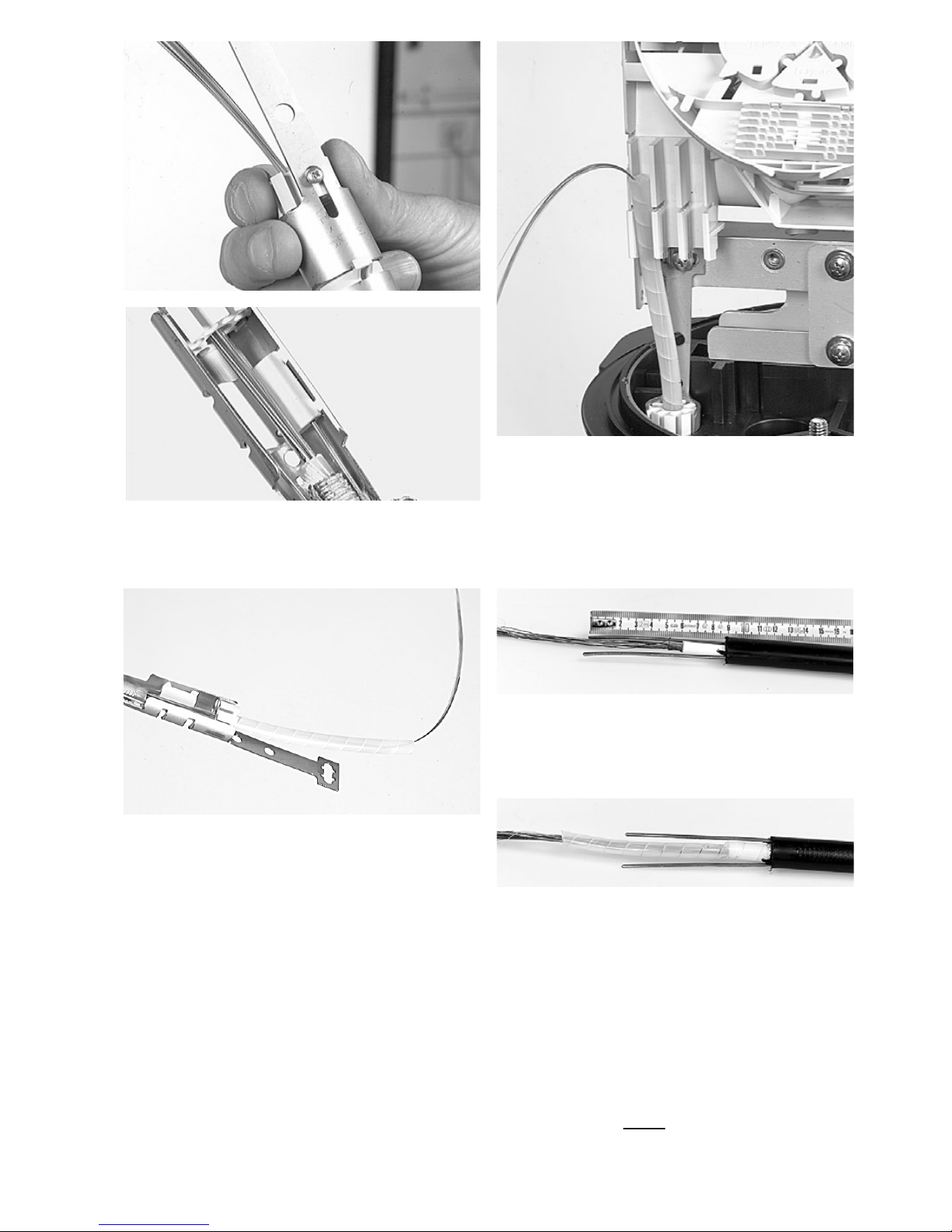
4.2.27 Match the spiral tube on the tubeholder, mark and cut the
spiral tube from this mark. Remove element per element the ID cords
or compact cable sheet (Microgain™, Compacttube™, ...) till about
10 mm after the spiral tubes; use teflon to bundle the fibers and the ID
cord. Position the small spiral tubes in the respective tubeholders.
Bottom picture shows compact cable sheet.
Page 15
15
4.2.36 Fix the round port cable fixation bracket (using a Phillips
screwdriver) on the bottom bracket.
4.2.f Drop cable preparation (16 port base)
4.2.37 Remove the cable jacket for 2.2m.
4.2.34 Put the fibers in the breakout through the center (put the tube
stop at cable jacket side) and slide the breakout on the bracket and fix
it with the screw.
4.2.35 Insert the ST (spiral tube) over the fibers into the breakout till
the tube stop.
0pen the round port and place the heatshrink as discribed in loose tube
preparation.
4.2.38 If ports 3-4-5-6-7-8-9-10 are used, cut strength member on
75mm length.
If ports 11-12-13-14-15-16-17-18 are used cut strength member on
90mm length and cut the central core at 30 mm from the jacket.
4.2.39 Put the Spiral tube on the cable
Page 16

4.2.43 Remove the ID cords or compact sheet till about 10mm after
the spiral tube; use teflon to bundle the fibers and the ID cord. Position
the spiral tubes in the respective tubeholder. Put the tube holder
retainer.
16
4.2.40 Fix the strength member plates in the closure.
Use FACC-DSCT for dual strength member cables.
4.2.41 Fix the cable in it.
4.2.42 Install the heatshrink (see section 5).
Page 17

17
5 Installation of the heatshrink
5.1 Oval port
5.1.1 Clean by using the cleaning tissue. Abrade the port.
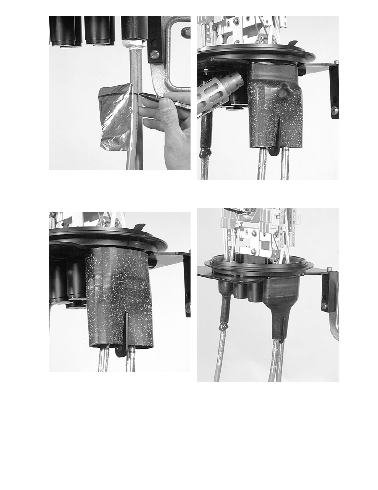
5.1.2 Clean and abrade the cable.
5.1.3 Remove the packing bag out of the seal, push the seal
upwards to the base and mark the cable flush with the seal. Make sure
the non-coated zone butts up against the base.
Page 18
18
5.1.4 Match the blue line of the aluminium protection foil with the
marks on the cables. Wrap aluminium cable protection foil around the
cable (the aluminium foil should not be more than 30 mm inside the
sleeve.
5.1.5 Push the seal against the base and place the clip.
5.1.6 Start heating the seal on the base, and wait one minute and
shrink in spiral movements downwards.
5.1.7 Hold the cable in position. Shrink till the green painting dots
become black, and the hotmelt is visible on the bottom. Postheat the
clip on both sides till the adhesive shows a proper flow on the clip
between the two cables.
Do not move the FIST-GCO or cable during 20 minutes.
Page 19

19
5.2 Round port
5.2.1 Repeat all the steps as discribed in oval port.
5.3 16 port base
5.3.1 It is recommended to use the hingable workstand.
Note: use the appropriate seals for the ports.
Fibers can be routed between OS1, OS2, ES1 and ES2. In case that
fibers have to be routed from SIDE-O (Odd portnumbers) to SIDE-E
(Even portnumbers), use the window (see picture). Select the cable
termination as such, that a minimum of fibers will cross and have to be
routed through the window. Therefore the selection of the ports
according to the cable lay-out is important.
6 Fiber routing
6 PORT BASE: Ports (1+3), (6+8) for cables to (S2). Ports (5+7), (2+4)
for cables to (S1). Verify the position of two cables if they are placed on
the same side (next to each other) because the total amount of loose
tubes in ports (1+3) or (2+4) or (5+7) or (6+8) can never be more than
mentioned in the capacity of the tube holder.
S1 side
S2 side
To E or
O side
Page 20

20
6.3 To remove push the two snapfits at S2 UMS-profile and slide the
wraparound plate towards S1 UMS-profile.
6.1 Remove the VELCRO and routing block cap. To remove the
routing block cap lift the two snaps at one side of the routing block cap.
6.2 Fix the wraparound groove plate on the UMS by putting the
plate with the long protrusions in the S1 UMS-profile and sliding the
plate in the S2 UMS-profile until it snaps. (Do not leave gaps between
groove plates).
6.4 Place a tray in the wraparound groove plate; do this by pushing
the lip on the groove plate (lowest possible position) slightly down with
the tray and move the tray lateral into the hinge-cavities of the groove
plate. To snap the High Capacity Single Element tray (HCSE) in the W/a
single fiber groove plate leave always one hinge facility open between
Fasblock or previous tray and the HCSE-tray.
16 PORT BASE: Ports (1+3+5+11+13), (2+4+6+12+14) for cables to
(S2). Ports (5+7+9+15+17), (6+8+10+16+18) for cables to (S1). Verify
the position of two cables if they are placed on the same side (next to
each other) because the total amount of loose tubes in ports going to
one tubeholder can never be more than mentioned in the capacity of
the tubeholder.
S1
S2
Page 21

21
6.5 To remove the tray put the fiber guiding pin between lip on
wraparound groove plate and tray and move lateral towards S1.
6.6 Identify the tray to be worked on and make it accessible. If the
routing block and trays are in vertical position you will have to support
the trays above the selected one using the tray wedge which fits in the
cavities of the wraparound groove plate. Position the wedge carefully
such that the groove is still accessible for the fibers and be careful not
to push the wedge against fibers. To remove the wedge,use two hands
to pull on both ends (near the groove plate).
6.7 Route the fiber in the grooves of the wraparound groove plates
to the entrance of the identified tray. Fiber must be routed in the
groove below the hinge of the tray!
6.6 Pull gently on the fibers in the tray and make sure that the fibers are
well contained in the routing block and wraparound groove plate.
6.9 Store the fibers temporarily on a tray (picture shows the case
of a loopback).
6.10 Storing dark fibers can be done in different ways.
1) Organise dark fibers into the different trays, following instructions
as described.
2) Organise dark fibers together into the first available tray (i.e. with a
max. of 24cut or 12 loops primary coated fibers in one SE-tray).
Page 22

7.2 SMOUV in SE tray.
7.5 ANT in SC tray.
7.3 SMOUV in SC tray.
7.4 ANT in SE tray.
22
7 Fiber routing on tray
7.1 Take the splice protector and put it centred towards the splice
holder
7.6 Ribbon 4/8 tray.
7.7 Ribbon 12 tray.
Page 23

23
8 Tube holder capacity and tray identification
Number x outer diameter loose tube (mm)
8.1 Use a permanent marker en to write on the tray.
9.1 In case of cable shield termination,connect the shield
continuity wires on the shield mounting bracket
9 Cable grounding/shielding
9.2 In case of grounding,mount grounding wire on the grounding
bolt
Page 24

10 Closing the closure
10.1 Remove the outer bag and place the Silica gel in the closure
(be careful, do not disturb any fiber or tube routing)
10.2 Place the o-ring back on a clean base and place the dome on
top of it.
10.3 Close with clamp.
11 Important steps during installations
• Make sure that grooves on the wraparound groove plate are clean.
• Clean the fibers.
• Be sure that fibers are not stored to tight in the trays, to prevent
stress on the fibers.
• Loose tubes routed up to the tube holder should be routed in such
a way that one still has complete acces of the stored tubes
between UMS profile.This is needed for later routing of loose
tubes from the loops to the tube holders without creating crossings
and without creating disturbtions on the loose tubes allready
routed up to the tube holders.
• Use correct lengths in the tubeholder.
• Make sure not to loose ID.
• Use only 45mm long SMOUV.
• Be secure when preparing window cut on loose tube cable for
storing uncut fibers.
• Avoid in all cases crossings of fibers and loose tubes in the cable
brackets.
• When using cables with a diameter smaller than 12mm in a cable
bracket,bend the sharp edges towards the cable and use some
tape around the bracket to protect the heatshrink.
• Replace the Silica gel each time the closure has been opened.
• Do not place the aluminum protection foil too deep in the
heatshrink.
12 Re-arrangement
Avoid to pull fibers inbetween groove plates.
Avoid fiber movement between tubeholder and first containment lip
on the routing block.
Take special care rearanging fibers from E to O side or reverse.
If accidentaly active fibers are removed from the containment
devices,reposition them carefully.
TC 574/IP/2 07/00
Tyco is a trademark. Teflon is a trademark of E.I. du Pont de Nemours. Velcro is a trademark of Velcro Industries B.V.
The information given herein, including drawings, illustrations and schematics which are intended for illustration purposes only, is
believed to be reliable. However, Tyco Electronics makes no warranties as to its accuracy or completeness and disclaims any liability
in connection with its use. Tyco Electronics’ obligations shall only be as set forth in Tyco Electronics’ Standard Terms and Conditions
of Sale for this product and in no case will Tyco Electronics be liable for any incidental, indirect or consequential damages arising out
of the sale, resale, use or misuse of the product. Users of Tyco Electronics products should make their own evaluation to determine
the suitability of each such product for the specific application.
Tyco Electronics Raychem NV
Telecom Outside Plant
Diestsesteenweg 692
B-3010 Kessel-Lo, Belgium
Tel.: 32-16-351 011
Fax: 32-16-351 697
www.tycoelectronics.com
www.telecomosp.com
 Loading...