

Page 1

FOSC-400D5
INSTALLATION INSTRUCTION
Fibre Optic Splice Closure with
integrated organiser system
Page 2

Page 3

1 General
1.1 The installation instruction describes the necessary steps to install the
FOSC-400D5. The product may be used on an optical fiber cable using loose tube and slotted core
constructions as well as ribbon fiber cable.
1.2 The FOSC-400D5 kit is supplied with one splice tray organizer. Each tray accommodates
up to 36 fiber splices max. Supplementary tray kits may be used (up to 7 extra trays maximum per
closure), increasing the capacity of FOSC-400D5 up to 576 single fusion splices.
1.3 The splice tray accommodates fusion splice protection type such as Raychem SMOUV1120-serie and mechanical splices (GTE, ATT, CSL,FIBRLOCK, SIECOR, AMP or other
similar products).
1.4 FOSC-400D5 has one oval cable entry port which can handle 2 cables. Five large
circular ports will handle one cable each.
1.5 The FOSC-400D5 can be installed in direct buried, manholes or aerial locations
Page 4
Number of organizer
trays in kit.
A closure:0-2
B closure:0-4
D closure:0-8
Ground feed thru lug(s)
G = Grounding
N = None
Raychem Customer
Specification Nnumber
Closure size: A, B or D
Number of round ports
Type of tray
S: only mentioned if it
is the tray, with Stacked
splices (EUR design).
There is no indication
if the splice modules are used
(US design).
Splice capacity of
each organiser tray:
A Tray: 08 or 16
B Tray: 12, 16 or 24
D Tray: 36, 48 or 72
No trays = NT
Cable Blocking
Components
B = Blocking
N = None
Valve for flash
Test
V = Valve
N = None
Ex. FOSC-400D5-36-1-NNN-A6007
D5 D size with 5 circular ports
36 Tray for upto 36 splices using splice modules
1 Closure is delivered with 1 tray
NNV The closure is not equipped with cable blocking, but has a valve for flash testing and no
components for electrical grounding of cable
A6007 Customer control number
2 Product description
2.1 Product designation
Raychem Total closure Outer dia Max.fusion Cable diameter in
description length closure splice capacity Circular port Oval port
min. Max. (250μ fibers) min. max. min. max.
(body) (body + (*) (*) (**) (**)
clamp)
FOSC-400A4 420 152 205 32 5 19 10 25
FOSC-400B2 540 152 205 96 5 32 10 25
FOSC-400B4 540 152 205 96 5 19 10 25
FOSC-400D5 710 240 285 576 5 32 10 25
FOSC sizing information (dimensions in mm)
(*) Cable diameter for 1 cable/port
(**) Cable diameter for 2 cables/port
FOSC-400X X - X X X - X - X X X - X X Y Y
Page 5
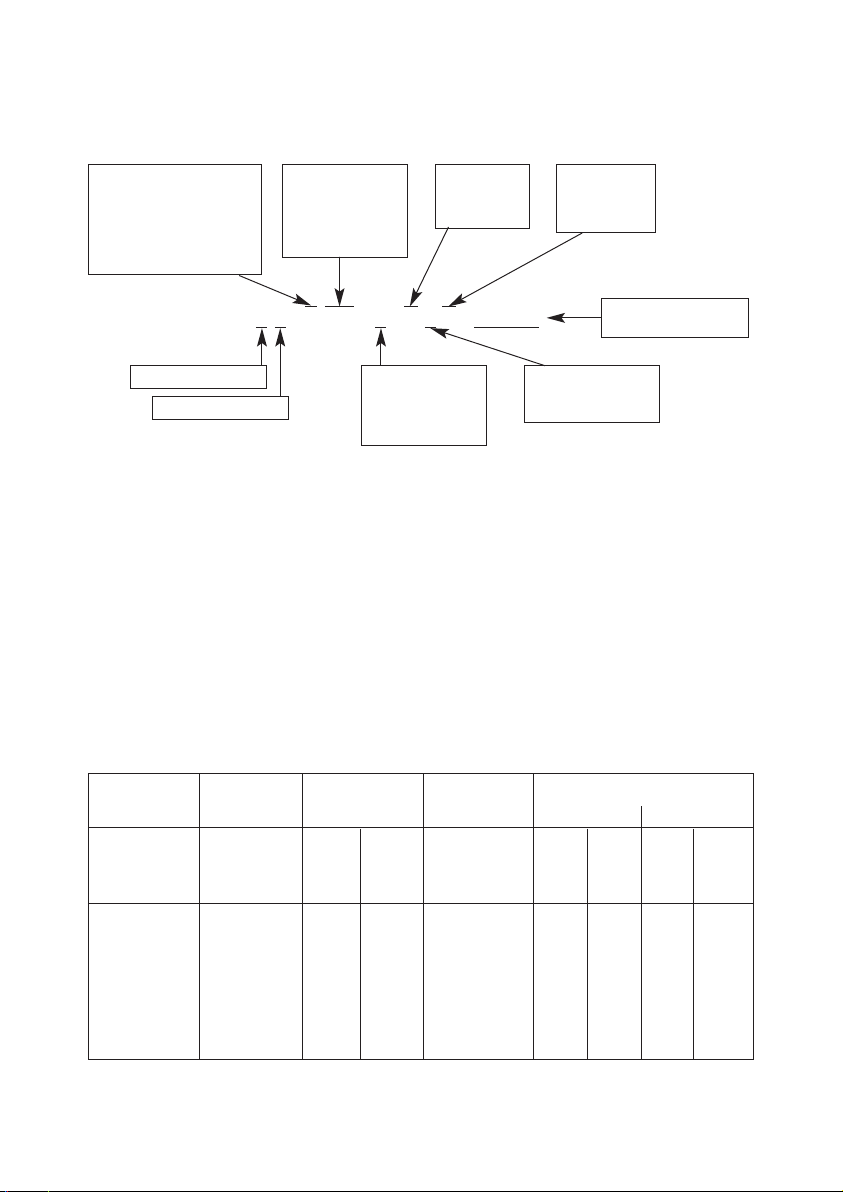
2.2 Content FOSC-400D5-36-1-NNV
- Dome with valve
- Base with strength member connections
and one tray assembly
- Clamp
- Velcro strap
- Oval outlet seal kit
- Sealing ring
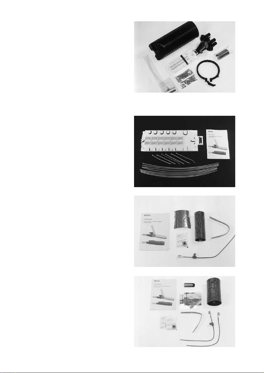
2.3.1 Tray kit
FOSC-D-TRAY-36-1
- One tray for 36 fusion splices
- Tray lid
- Tie-wraps
- 8 Large transportation tubes (id.= 2.8 mm)
2.3.2 Cable seal-kit
FOSC-B/D-CSEAL-1-NT
- Aluminium cable protection tape
- Heat-shrinkable cable sleeve
- Cleaning tissue
- Abrasive strip
* Shield continuity wire*
* Shield continuity connector*
* Installation instruction
*
2.3.3 Oval outlet cable seal kit
FOSC-B/D-CSEAL-2-NT
- Heat shrinkable sleeve
- Branch-off clip
- Aluminium cable protection tapes
- Abrasive strip
- Cleaning tissues
* Shield continuity wires*
* Shield continuity connector*
* Installation instruction*
2.3 Supplementary kits
Page 6
2.3.4 Loose tube slack tray
FOSC-D-BASKET
- Slack tray
- Tie-wraps
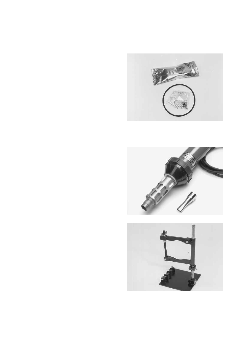
2.3.5 Re-entry kit
FOSC-D-O-RING-SEAL-KIT
- Desiccant
- Sealing ring
- Cleaning tissue
2.4.1 FACC-HEAT-GUN-220V
Hot air gun CV 1981 (1460 Watt) and Reflector
PR 26.
Min. required hot-air temperature: 350°C.
2.4.2 FOSC-WORK-STAND
FOSC holder device
* Only included if the seal kits are ordered separately.
2.4 Accessory kits
2.4.3 FOSC-400D-POLE-MOUNT
Bracket for mounting D-closure to pole or wall.
2.4.4 FOSC-D-VAULT-BAG
Flame retardant bag to cover closure for vault application.
Page 7

3 General precautions
3.1 Do not use damaged sleeve nor trim heat-shrinkable sleeve before installation.
3.2 The FOSC-400D5 closures can be installed at temperatures between -1°C and +45°C.
3.3 Generators used should have enough capacity for the hot air gun utilisation.
Optical fiber infrastructure network elements may contain end of optical fiber attached to the
optical output when the device is operational. Laser radiation can seriously damage your eyesight. Please follow your local safety guidelines.
4.1 Attach the closure in the FOSC work
stand using the nut and the bolt. Loose and
remove the clamp.
Push the lever down to release the locking tab.
Open the clamp lever and release the clamp
using the lever legs. Remove the dome, the
sealing ring and store carefully for later use.
4.2 Open the oval port for cable entry by
cutting the port at the ridge with a hacksaw.
Deburr the inner edge of the port opening with
abrasive strip.
4.3 Remove any dirt, mud or other
contaminants from the cable sheath for
approximately 2 meters with a clean cloth. Take
the oval cable seal and slide it over the cables.
The non-coated edge of the sleeve and the
arrows should be pointed to the base of the
closure.
4 Cable installation in oval outlet
Page 8

4.4 Slide the cables through the opened
oval port. Prepare cables as described in section
5 (cable preparation).
5.1 Remove the cable sheath (and shield if
present) over a length as required by locally
approved practice (e.g. 1,5 meters). Clean
filling compound from fiber tubes and cut central strength member at a distance of
230 mm from outer jacket.
Note. For the ribbon cable the maximum
striplength is 1.5 m.
5.2 If a shield continuity is required, cut
cable sheath axially for 25 mm from cable ring
cut. Crimp shield clip on cable sheath with pair
of pliers. Protect the clip with self adhering tape.
5.3 Cut the loose tube, at a distance of
40 mm from the cable ring cut and remove and
degrease fiber bundle. Select a
transportation tube which fits over the loose
tube. Slip transportation tube over fibers and
the loose tube.
NNoottee
: for slotted core cable: use an
appropriate kit which converts the slotted cable
construction into a loose tube
construction.
5 Cable preparation
Strength member
Buffer tubes
Outher cable
sheath
tab for bonding
wire
Page 9

5.4 Align cable ring cuts with edge of base.
Slide strength members into clamps and
tighten. Cut away the excess length of strength
member.
5.5 If required, connect shield continuity
wire of both cables with shield continuity clip.
Talk pairs, if present, will be connected together
according to the local procedures.
6.1 Thoroughly clean oval port and cable
sheath with the cleaning tissue over a
distance of 100 mm from the edge of the port.
6.2 Abrade oval port and cable sheath
circumferentially on the cleaned area with the
abrasive strip. Remove any abraded material
with a clean cloth.
6 Sealing of oval outlet
Page 10

6.3 Place oval seal over the oval port and
cable. Mark the sleeve length onto the cable.
6.4 Match the blue line of the aluminium
cable protection foil with the marks on the
cables. Wrap aluminium cable protection foil
around cable.
6.5 Slide the oval cable seal over the oval
port. Install the branch-off clip. Check that the
heat-shrinkable sleeve butts up against the
FOSC-base and the branch-off clip is
completely inserted. Tape the two cables
together.
6.6 Shrink the oval cable seal on the FOSCbase side with the recommended hot air gun
device with reflector. Shrink sleeve until the
green thermo-indicating paint is
converted to black. (Make sure the hot-air temperature is at least 350°C).
(If a FACC-HEAT-GUN-220V is used, set position on scale 10).
Page 11

6.7 Shrink down the end of the sleeve on
the cable side. Heat until the sleeve shrinks
down on the cables and take care that the
green thermo-indicating paint is converted to
black. Postheat the clip on both sides till the
adhesive shows a proper flow on the clip
between the two cables.
Wait until the sleeve is cool to the touch
before moving the cables.
7.1 Lift the top tray to expose the bottom
tray, which should be filled first. Use the tray
support wedge attached to the bottom of the
second tray to hold it out of the way.
7.2 Route the distribution tubes around the tray holding bracket so that they will reach the distribution side of the tray.
7.3 Remove the tray cover and align the transportation tubes along the outer sides of the tray.
7.4 Place a pen mark on each tube 5 mm
beyond the tie-down slots. Use a buffer tube
cutter to cut each tube at the mark, and remove
the excess tube from each fiber group. Clean
the fibers from the grease.
7 Positioning the transportation tubes and fibers
Tray support latch
Pen mark
Distribution
Feeder
Page 12

7.5 Secure the transportation tubes to the
tray with tie wraps as shown.
7.6 Arrange the fiber around the tray for storage until the fiber is to be spliced.
7.7 When all fibers to be stored in this tray have been arranged, replace the tray cover.
7.8 Repeat steps 7.1 through 7.7 for each tray until all fiber has been stored in a tray.
8.1 To add splice trays, put the tray support
latch down, hold the tray vertically over the tray
holder bracket, and insert the tray hinge into the
next unoccupied slot on the tray
holder bracket. Put the tray support latch up to
lower the tray.
9.1 Fiber placed on one tray can be spliced
with fiber from another tray by using an
intertray jumper to route the fiber to the
desired tray.
8.2 To remove splice trays from the FOSC-400D base, raise the tray and put the tray
support latch down. Pull the tray hinge out of the tray holder bracket, releasing the tray.
Tray support
latch
Intertray
jumper
9 Intertray jumpers
8 Add or remove splices trays
Page 13

9.2 Place appropriate intertray identification markers on a transportation tube.
(Intertray ID markers are marked “1TO” through “8TO” and “1” through “8”, to indicate which tray
the jumper came from and which tray it is going to.)
9.3 Guide the desired fibers through the marked transportation tube (now called the intertray
jumper).
9.4 Secure one end of the intertray jumpers to the originazing splice tray with two tie wraps. If
you have to remove existing tie wraps, cut and replace one at a time to avoid moving the existing
transportation tubes.
9.5 Guide the jumper through the opening in the tray mounting bracket to the appropriate
destination tray and position it in the tray (see section 7).
9.6 With a pen, mark the jumper 5 mm beyond the tie wrap slot. Use the buffer tube cutter to
cut the jumper at the mark, and secure the jumper to the splice tray with two tie wraps. The fibers
may now be stored or spliced.
10 Fiber splicing and storage on trays
10.1 Always begin splicing with the bottom tray. Lift the remaining trays and secure them with
the tray support on the underside of the second tray.
10.2 Remove all stored, unspliced fibers from the tray and clean those that will be spliced. Refer
to the splice manufacturer’s instructions for directions on fiber splicing.
10.3 Store the first completed splice in the
top splice slot (the slot farthest from the hinge).
Coil the slack loops around the tray in an orderly
fashion. The six splice modules can be moved
or removed to accommodate your splice arrangement; however, the lowest splice module
(the one closest to the hinge) can not be closer
to the hinge than its
position indicates. No more than six modules
can be placed in one splice tray.
10.4 Subsequent splices should be stored in the tray from the top slot down. Slack loops can
be secured under the tabs around the outside edges of the tray and in the spaces between splice
modules.
10.5 When you have completed all the splices in the tray, replace the tray cover. Repeat steps
10.1 - 10.4 until all splices are complete and all tray covers habe been replaced.
Page 14

10.6 Secure all trays to the bottom tray
bracket with the Velcro strap as shown.
11.1 Identify each ribbon. Split each ribbon
into individual fibers. Follow the
manufacturer’s recommendations for the splitting ribbons. Splice and organise the fibers as
explained in section 10.
12.1 Open and remove the desiccant bag
from its package and place the desiccant bag
on the upper tray. Secure the trays and the
desiccant bag with the Velcro strap.
12.2 Ensure seal areas and sealing ring are
clean and that the sealing ring is in place at the
base.
12 Dome installation
11 Splicing of ribbon cable
Velcro strap
Ribbon
Important.
Make sure the sealing ring is well
positioned.
Page 15

12.3 Place the dome carefully over the trays
onto the base. Put the clamp around the
base/dome interface. Close the clamp.
13.1 Remove the clamp.
13.2 Remove carefully the dome and the sealing ring. Keep the sealing ring and seal area of the
closure free of dirt. (If needed rinse with clear water).
13.3 The dome may be reinstalled by following the procedure as described in section 9.
Replace the 75 grams of desiccant.
The sealing ring has also to be replaced if damaged. A
new sealing ring and 75 gram of desiccant can be ordered: FOSC-D-O-RING-SEAL-KIT.
13 Re-entry
14 Cable installation in circular outlet
14.1 Open the port for cable entry by
cutting the port at the ridge with a hacksaw.
Deburr the inner edge of the port opening with
abrasive strip.
Page 16

14.2 Remove any dirt, mud or other
contaminants from the cable sheath for
approximately 2 meters with a clean cloth. Take
the cable seal sleeve from the kit FOSC-B/DCSEAL-1-NT and slide it over the cable. The noncoated edge of the sleeve and the arrows
should be pointed to the base of the closure.
14.4 Slide the prepared cable through the
opened entry port and install the
transportation tubes described in section 5.
14.5 Align cable ring cut with the edge of
the base. Slide strength member into clamp and
tighten the nut. Cut away the excess length of
strength member.
14.6 Thoroughly clean port and cable
sheath with he cleaning tissue over a
distance of 100 mm from the edge of the port.
14.3 Prepare the cable as outlined in section 5 “Cable preparation”.
Page 17

14.7 Abrade port and cable sheath
circumferentially on the cleaned area with the
abrasive strip. Remove any abraded material
with a clean cloth.
14.8 Place cable seal over the drop outlet of
FOSC base. When cable seal butts against the
base, mark the sleeve length on cable sheath.
14.9 Match the blue line of the aluminium
cable protection foil with the marks on the
cables. Wrap the aluminium cable protection
foil around cable.
14.10 Slide the cable seal over the port and
shrink the cable sleeve on the base side with
the recommended hot air gun
device. Use the reflector to ensure heat
distribution around the outlet. Shrink sleeve
until the green thermo-indicating paint is
converted to black.
Note. Setting thermogun: FACC-HEAT-GUN -
220V in position 10. Minimum hot air
temperature should be 350°C.
Page 18

14.11 Shrink down the end of the sleeve on
the cable side. Heat till the sleeve shrinks down
onto the cable and the green
thermo-indicating paint is converted to black. A
ring of red adhesive should be visible at the
cable on the end of the sleeve.
Wait until the sleeve is cool to the touch
before moving the cables.
14.13 Re-install the sealing ring, the dome and the clamp (see section 12).
15 Additional cable installation
15.1 For each added cable use a FOSC-B/D-CSEAL-1-NT. For each added cable proceed as per
section 11. The fiber splicing is outlined in section 7.
15.2 Reclose the closure with the sealing ring and the dome.
16 Slack storage tray kit (FOSC-D-BASKET)
16.1 If uncut loose buffer tubes are to be stored, the tube slack tray must be mounted. Detach
the splice trays from the tray mount by removing the retention bar and pulling out
splice trays.
16.2 Install slack tray by pushing the slack tray into the groove of the tray holder bracket.
16.3 For storing uncut loose buffer tubes, slide the fibers and slack loose tubes through the oval
port, being careful not to kink the tubes.
16.4 Store the slack inside the tray and hold in place with tie wraps.
16.5 Position assigned fibers/transportation tubes to be spliced in the splice trays.
16.6 Replace splice trays in tray mount bracket. (Splice trays will now be mounted above slack
tray.)
Page 19

Page 20

TC 443/IP/1 11/95
Tyco Electronics, TE logo and FOSC are trademarks.
Velcro is a trademark of Velcro Industries B.V.
The information given herein, including drawings, illustrations and schematics
which are intended for illustration purposes only, is believed to be reliable.
However, Tyco Electronics makes no warranties as to its accuracy or
completeness and disclaims any liability in connection with its use. Tyco
Electronics obligations shall only be as set forth in Tyco Electronics’ Standard
Terms and Conditions of Sale for this product and in no case will Tyco Electronics
be liable for any incidental, indirect or consequential damages arising out of the
sale, resale, use or misuse of the product. Users of Tyco Electronics products
should make their own evaluation to determine the suitability of each such
product for the specific application.
Tyco Electronics
Raychem NV
Diestsesteenweg 692
B-3010 Kessel-Lo, Belgium
Tel.: 32-16-351 011
Fax: 32-16-351 697
www.tycoelectronics.com
www.telecomosp.com
 Loading...