

Page 1

FIST-MB2-T
INSTALLATION INSTRUCTION
Medium Box for Cable Termination
1 Introduction
1.1 Product description.
2 General
2.1 Tools
2.2 Kit contents
3 Installation and pre
assembling of box
3.1 Preparation of box
3.2 Opening of the ports.
3.3 Installation of wrap around groove
plates
3.4 Installation of the splicing trays
3.5 Mounting of the box on the wall
4 Cable installation
4.1 Cable preparation
4.2 Cable termination
4.3 Routing of the cable fibers
5 Pigtail installation
5.1 Installation pigtails with connectors
5.2 Installation of pigtails with Kevlar termination
5.3 Pigtail routing to the splicing trays
5.4 installation of the pigtail seals
6 Fiber organisation after splicing
7 Closing the box
8 Important steps
9 Rearrangements
Contents
1 Introduction
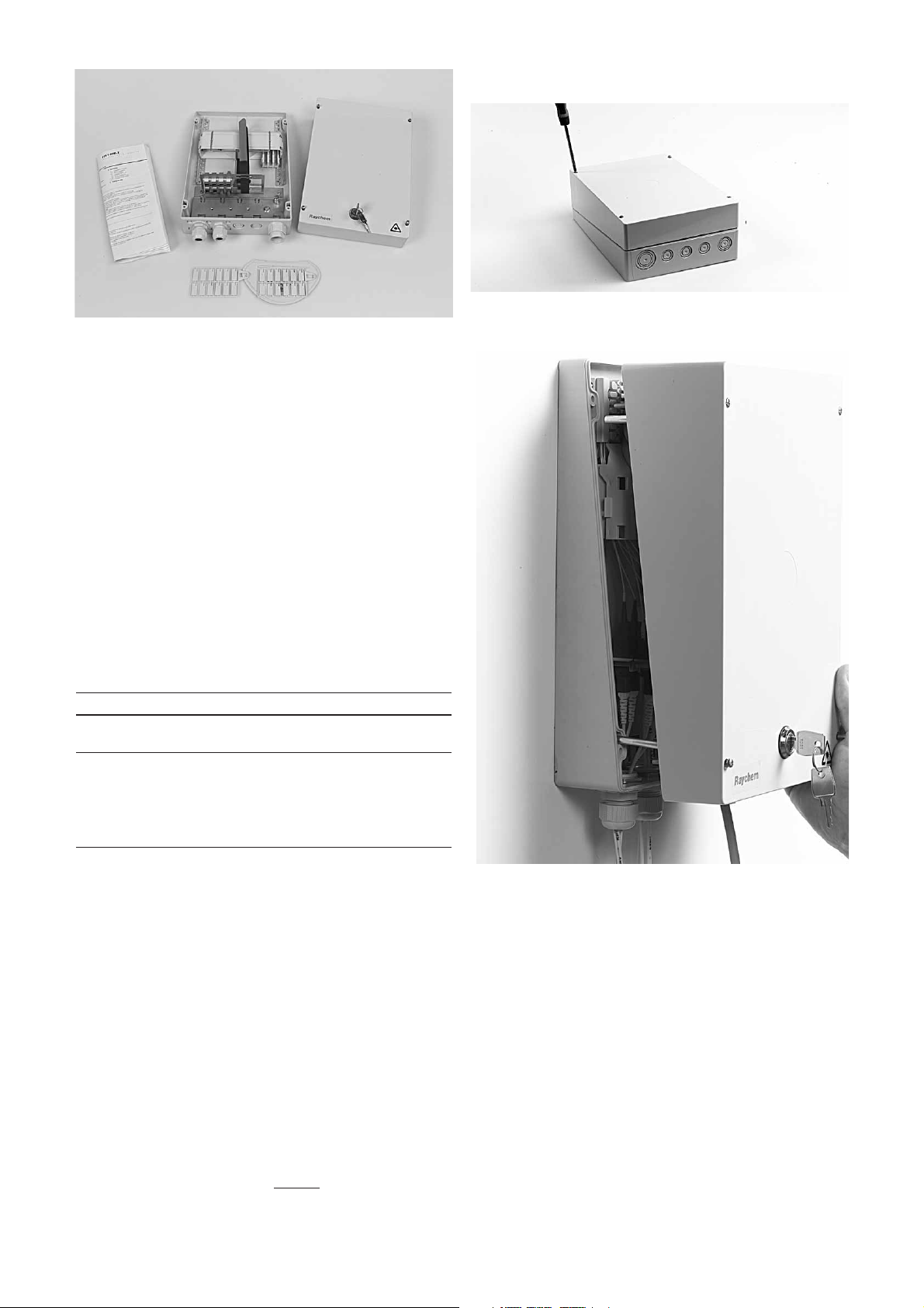
1.1 Product Description
The FIST-MB2-T is a Generic Box for a fiber management system that offers the function of splicing and patching.
It provides a mechanical and environmental protection for all the fiber optic components and permits easy
access by both the network provider and the customer. The box is applicable indoor and inside street cabinets.
The FIST-MB2-t box is designed to terminate, and patch fibers, it can handle up to 16 connectors.
2 General
2.1 Tools
Hammer
Screwdriver
Marker
Fiber guiding pin
FACC-tube-cutter-01 to cut loose tubes
FIST-GB-CUT-TOOL-PG16 to cut holes for glands
FACC-TUBE-Stripper-02 to strip loose tubes
FACC-HEAT-GUN-220V or 110V 1460W hot air gun to install the heatshrink cable seals
Page 2
2
3.1.2 In case of a box with lock, lift cover and remove the guiding
pins.
2.2 Kit contents
Depending on the network layout and the construction of the used
cables, the kit content may be different. Some of the components will
be pre-assembled in the box depending on the selection and the
ordering. The minimum content will be:
• 4 pcs of mounting bolts and plugs for wall mounting.
• The box base
• Pre installed - Universal Mounting System profile.
- Small fiber routing block with tube holders
- Tray lid and guiding pin and retainers
- Velcro strap
- FAS cap including the tray wedge
- Cable strain relief connectors and fixing plate
- patch panel with 2 anti movements strips
(AMS)
• Cable glands, including pigtail seals (4 pigtails per seal)
• Tiewraps
• The Cover (including 4 preinstalled screws).
• Installation instruction
2.3 Selection table
MB-2-T box capacity
W/A groove Type of tray max.number Capacity
plate units of trays connectors KTUs
8 FIST-SOSA2-8SC-X 8 16 8
8 FIST-SOSA2-8SE-X 4 16 8
8 FIST-GB2-FOR04-XX-2 4 16 n/a
6 FIST-GB2-FOR08-XX-2 2 16 n/a
4 FIST-GB2-FOR12-XX-2 1 12 n/a
3.1.1 Unlock the screws and remove the cover.
3 Installation
3.1 Preparation of box
Page 3
3
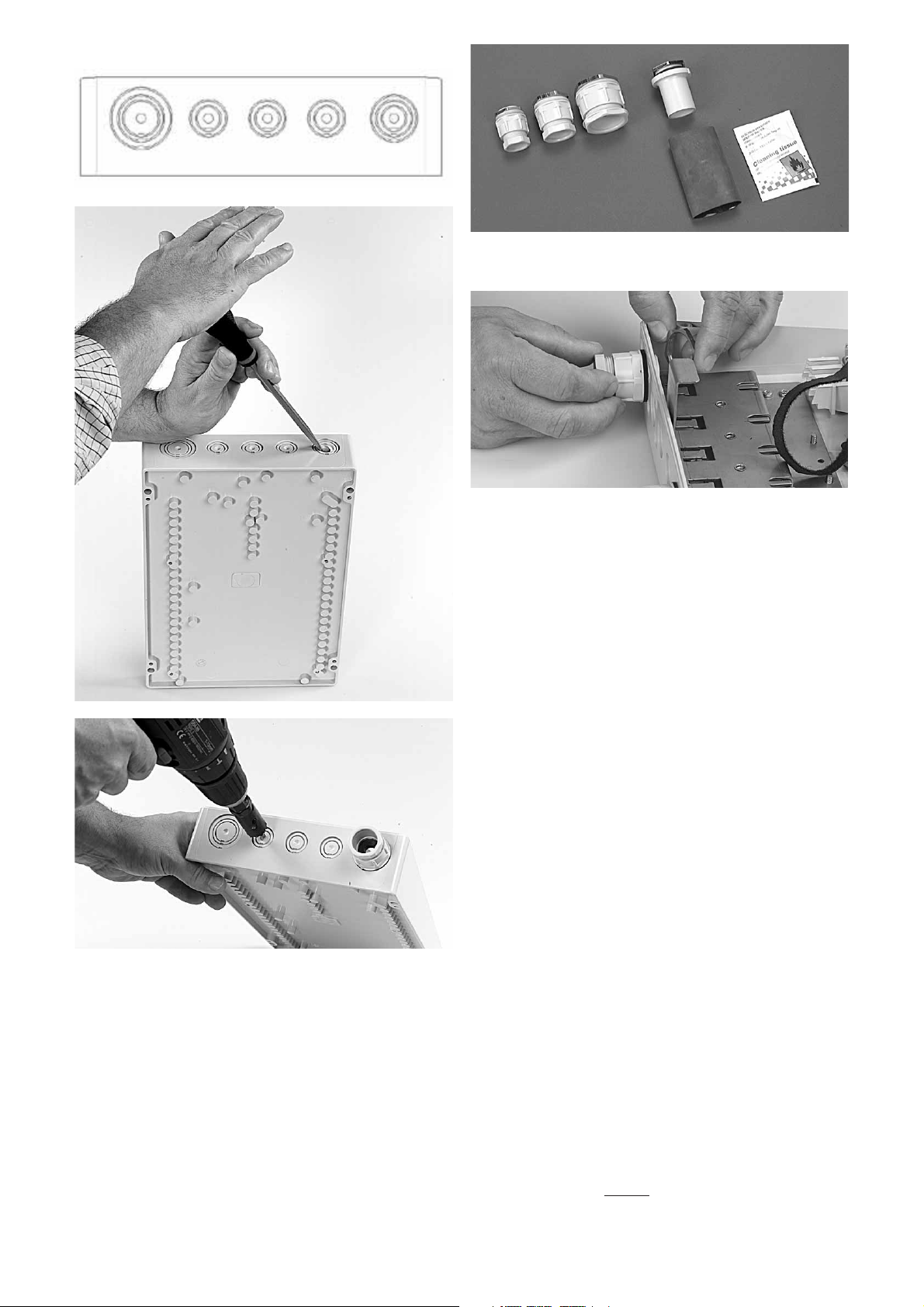
3.2.1 Drill or knock out the ports to be used, (cable in, port 1 - pigtails
out, ports 2, 3, 4, 5).
3.2.2 Select the appropriate gland depending on the cable diameter.
3.2.3 Install the glands in the selected ports by tighten the nut on the
inside of the box, do not forget to install the rubber ring on the outside
of the box.
123
45
3.2 Opening of the cable ports
Page 4
4
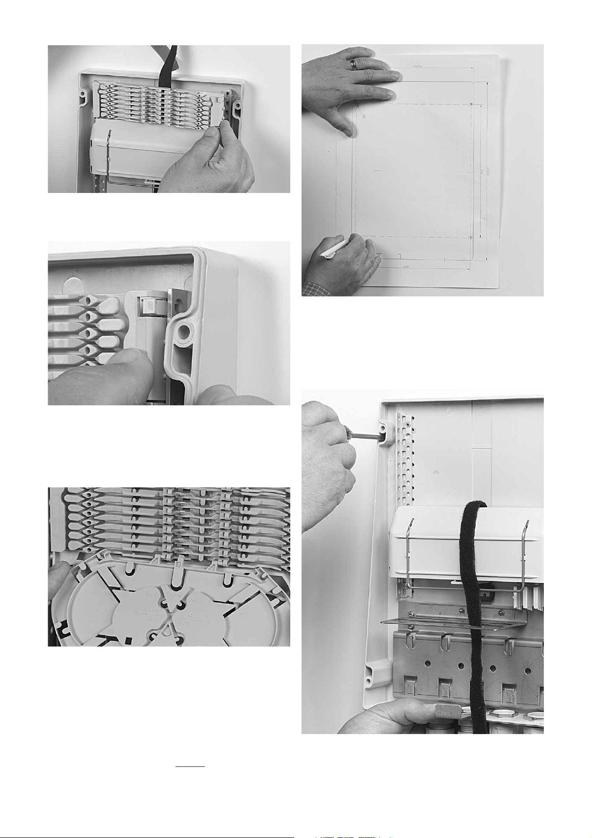
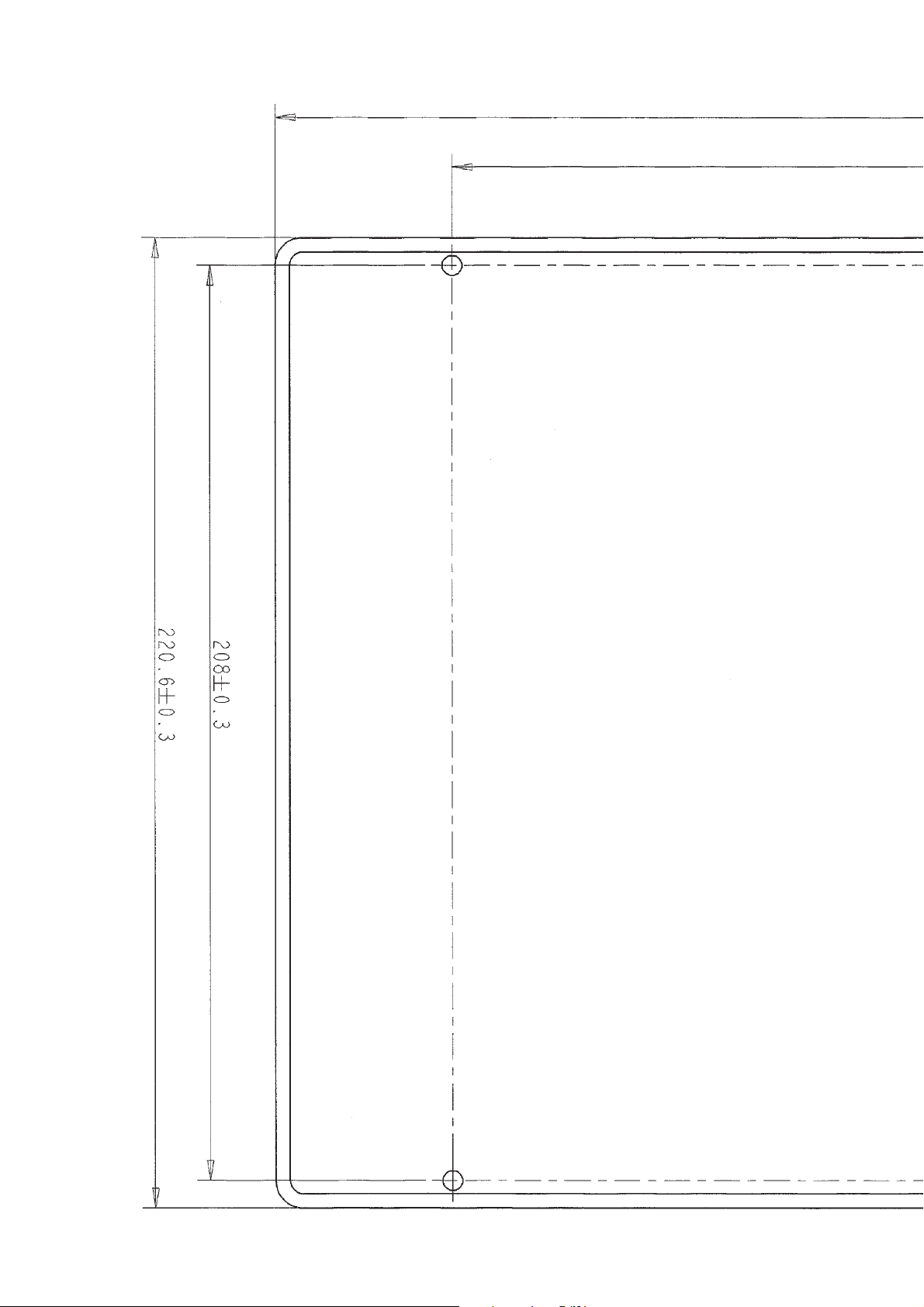
3.5.1. Place the template against the wall and mark the selected
mounting positions onto the wall.
3.5.2. Drill the holes (diameter. 6 mm, depth 60 mm) and place the
plugs into the holes.
3.5 Mounting of the box on the wall
3.5.3. Hold the base part onto the wall. Insert the screws and tighten.
3.4.1 Install the splicing tray by pushing the lip on the groove plate
slightly up with the tray and move the tray lateral from left to right into
the hinging cavity.
Note. 1 for single element start on the second position
leaving one position open between each of the trays.
2 For ribbon 4-8 trays the tray hinges have to be
inserted from right to left.
3.4 Installation of the trays
3.3.1. Take the groove plates and slide the long protrusions into the
left bracket of the UMS bracket.
3.3.2. Pull on the long snapfit towards the profile till it clicks in the
UMS bracket, start on the FAS block without leaving gaps between the
plates.
3.3 Installation of wraparound groove plates
Page 5
5
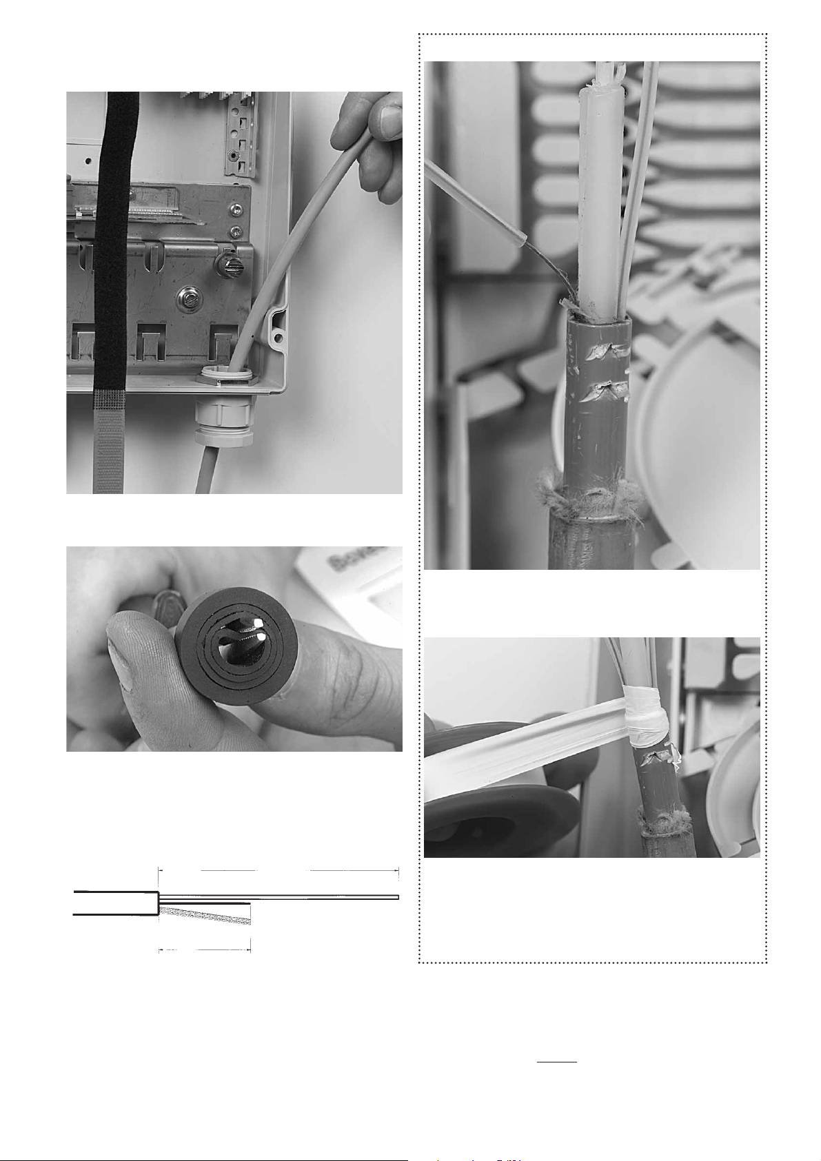
For slotted core cable only
4.1.3.1 Install a protection tube of 150 mm over the fibers of each slot
and slide it into the slot of the cable.
4.1.3.2 Protect the transition from the cable to the tubes with a few
layers of Teflon tape.
4.1.3.3 Consider the protection tubes now as loose tubes in the
installation.
4.1.1. Feed the cable through the cable port gland.
4 Cable installation
4.1 Cable preparation
4.1.2. In case the cable diameter does not match with the diameter
of the gland seal, remove the plastic nut, metal ring and rubber seal
inside the gland and peel out some of the break out rubber rings up to
the right diameter.
4.1.3 Prepare the cable according to the drawing, Strip and clean
the cable over a length of 1800 mm. and cut the strength member at
60 mm length.
1800 mm
60 mm
Page 6

6
4.2.3 Secure the cable with a tiewrap onto the cable attachment
plate.
4.2.4 Tighten the gland
4.3 Routing of cable fibers
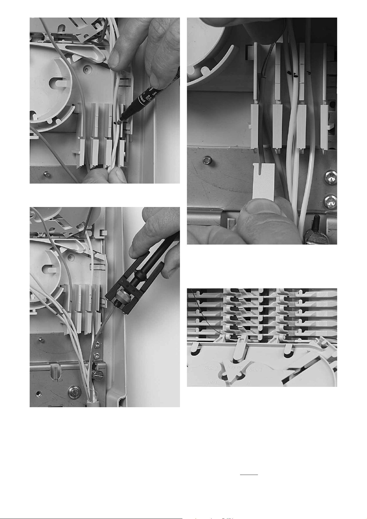
4.3.1 Allocation of the tubes in the tube holders.
Important; loose tubes should be routed up to the tube holder in such
way that access to all the tubes is possible at all times in case of re-
routing without crossings of already installed tubes.
4.3.2 Open the Velcro strap and remove the FAS block cap.
4.2.1 Pull the cable back in the correct position, the cable jacket
should protrude 30 mm into the box. passing the cable strapping point.
4.2 Cable termination
4.2.2 Insert the strength member in the strength member connector
and tighten the connector with a screwdriver. If necessary remove the
plastic core from the straight member till it fits in the strain relief
connector.
Page 7
7
4.3.3 Mark the tubes between the two marks on the tube holder.
4.3.5 Position the loose tubes in the tube holder and slide the tube
holder retainer with the snap forwards in the lowest possible cavity of
the tube holder above the loose tube(s). The tube holder retainer must
snap.
4.3.6 Route the fibers in the grooves of the wraparound groove plate
to the entrance of the identified tray. Fiber must be routed in the
groove of the tray hinge.
4.3.3 Cut and remove the excess of the loose tube and clean the
fibers.
Page 8
Page 9

Page 10
10
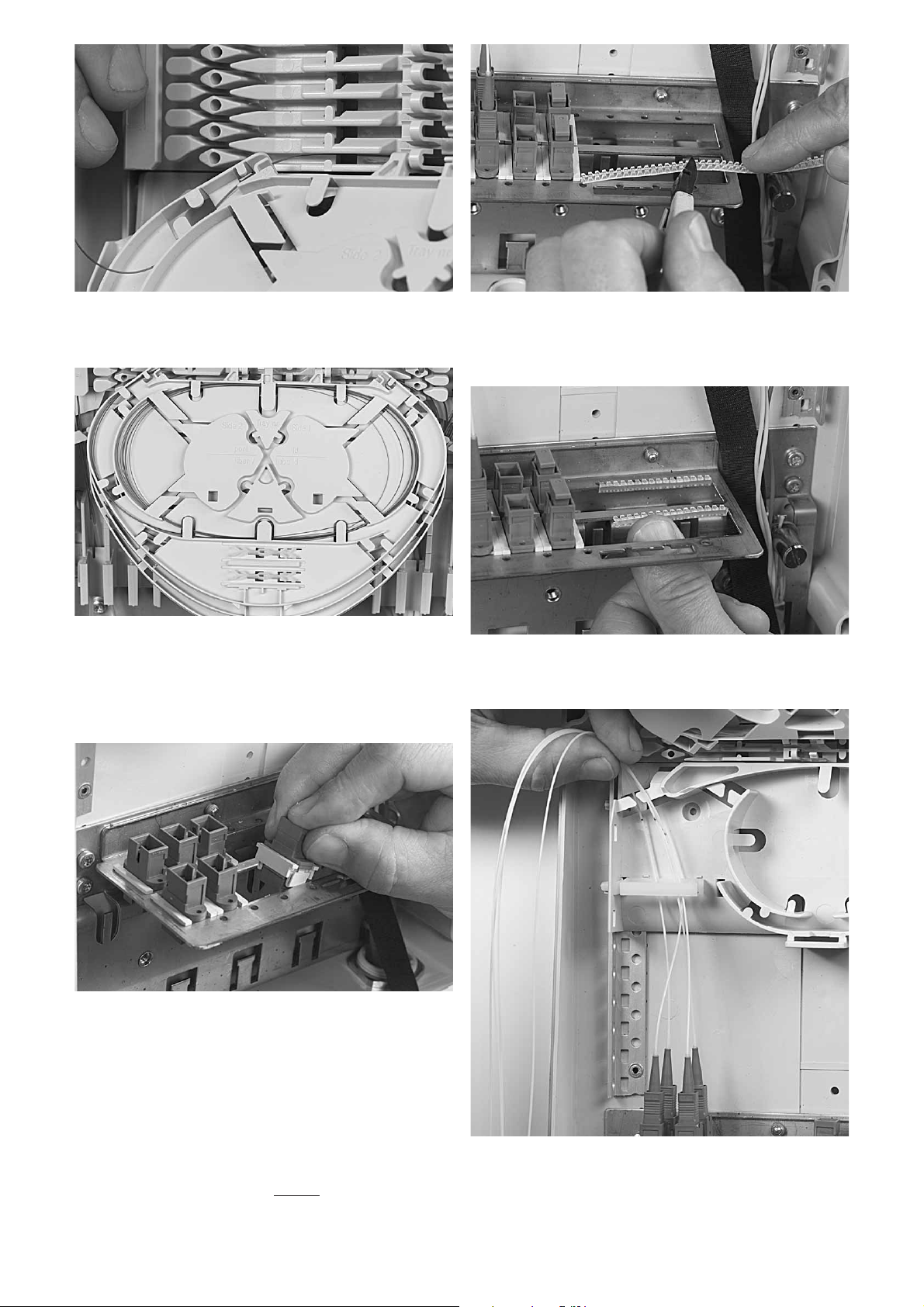
5.1.2 When all adapters are installed slide them to the left side of the
patch panel, measure the length of the Anti Movement Strip and cut
the AMS to length (distance of the opening minus 6 slots).
5.1.3 Install the anti movement strip (AMS) on both the slot sides of
the patch panel.
5.1.4 Mount the pigtail connectors in the adapters and route the
pigtails to the splicing trays.
4.3.7 Pull gently on the fibers in the tray and make sure that the
fibers are well contained in FAS block and wraparound groove plate.
4.3.8 Store the fibers temporarily on a tray.
5 Pigtail installation
5.1 Installation of pigtails with connectors
5.1.1 Connector adapters have to be installed in the patch panel.
Push the adapter from the top in the patch panel and slide it in position.
Page 11
11
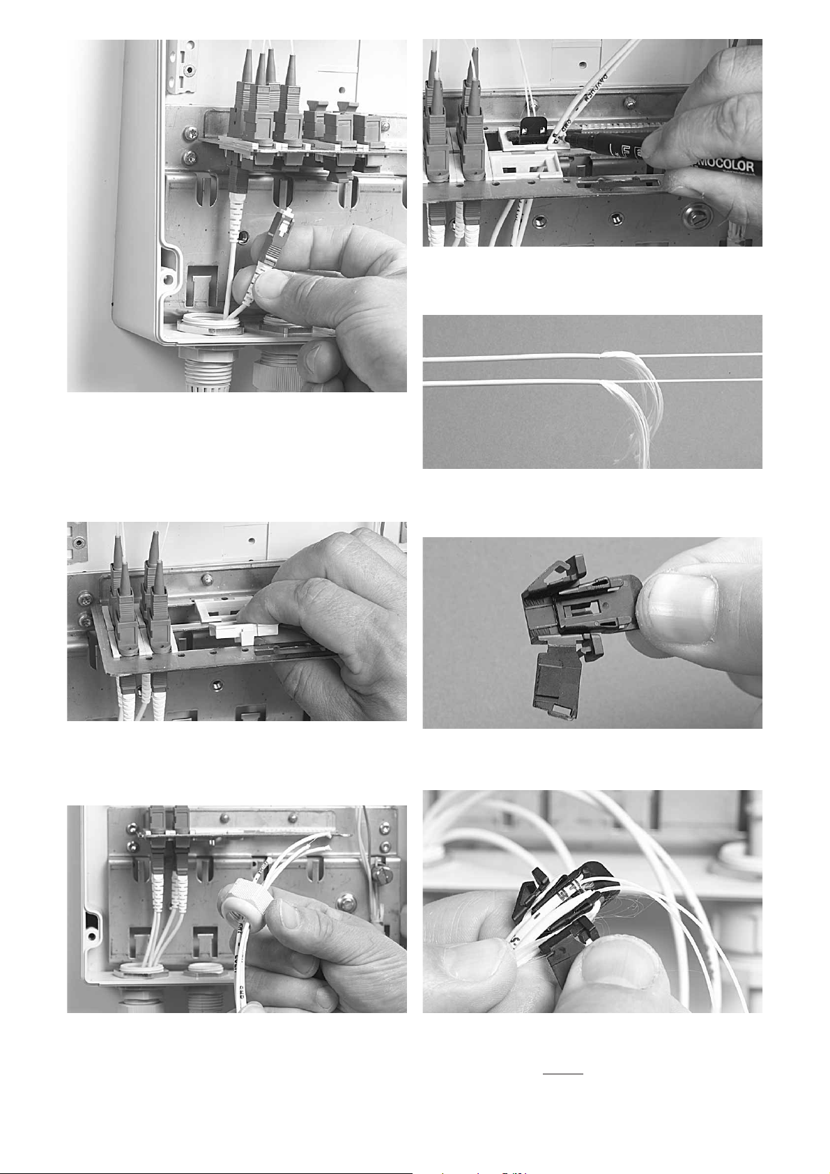
5.2.2 Slide the pigtail gland nut over the pigtails and feed the pigtails
through The gland and the patch panel adapter.
5.2.5 Mount the two pieces of the KTU together by sliding the inner
part in the outer part.
5.2.3 Pull the pigtails for 2000 mm through the patch panel and
mark them.
5.2.6 Take the two pigtails and bend the Kevlar over the inner part
lips back between the two parts of the KTU.
Mark the pigtails 50 mm away from the connector.
5.2.4 Remove the pigtail jacket up to the mark. Cut away the Kevlar
up to 50mm-100mm from the ring cut.
5.1.5 Remove the pigtail gland seal and nut , feed the jumper
connectors through the gland and mount the connectors to the
adapter on the patch panel.
5.2 Installation of pigtails with Kevlar termination unit
(KTU)
5.2.1 A Kevlar termination adapter has to be installed in the patch
panel. Push the adapter from the top in the patch panel, an slide it in
position. Each adapter can contain two KTUs.
Page 12
12
5.2.8 Cut the Kevlar yarns at the connector and install in the patch
panel adapter.
5.3 Pigtail routing to splicing trays
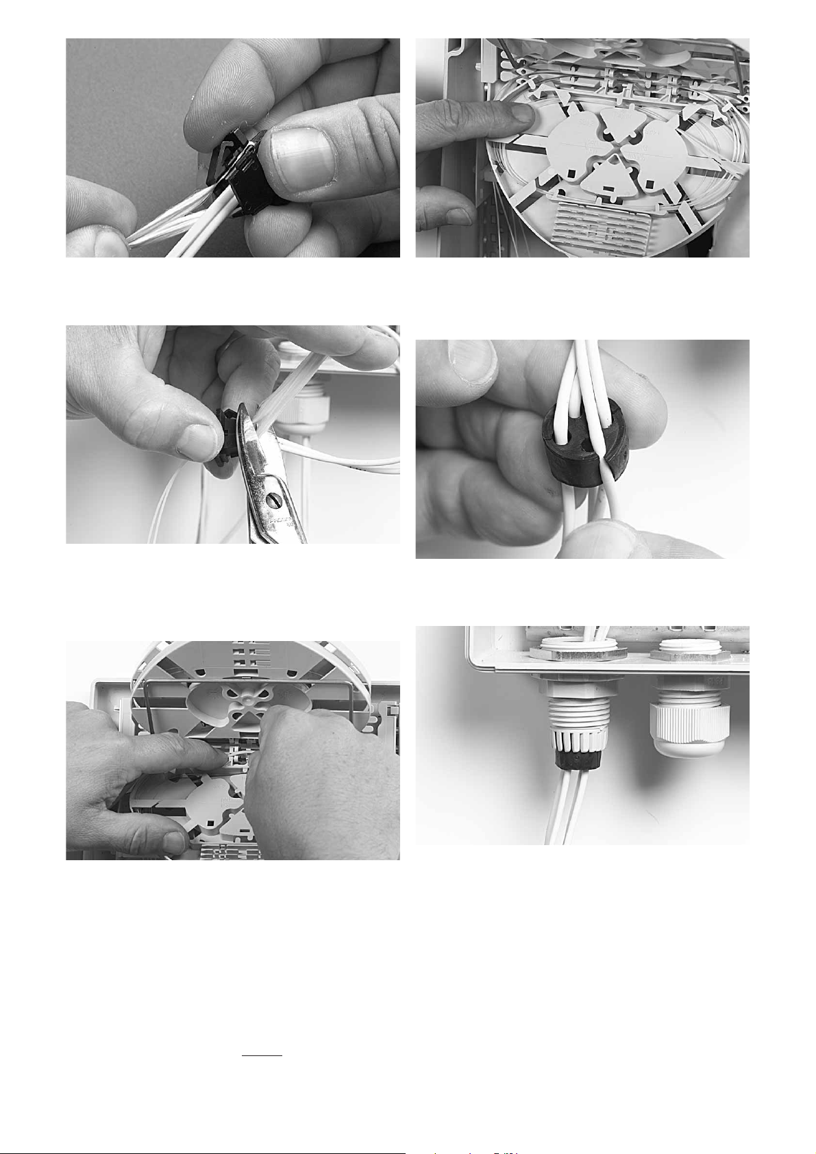
5.4.1 Insert the pigtails or jumpers in the rubber wrap around seal of
the pigtail seal.
5.4 Installation of pigtail gland seals
5.3.1 Guide the fibers to the cassette through the groove under the
tray hinge.
5.4.2 Position the rubber pigtail seal in the gland, avoid pigtail
crossings in the gland.
5.3.2 Store the pigtails temporary on the tray.5.2.7 Close the KTU connector by snapping the lid, and pull on the
Kevlar to slide the inner part backwards as far as possible.
Page 13

13
6.1 Take the splice protector and put it centered towards the
splice holder.
7.1 Install the FAS block cap and the retainer.
7 Closing the box
6 Fiber organisation on trays after splicing
6.2 Different types of splice holders can be fitted in the tray with
the use of an adapted splice holder.
7.2 Secure the splicing trays with the Velcro strap.
5.4.3 Tighten the gland nut on the pigtail seal.
Page 14

14
7.4 Place the cover on the box base and secure the cover with the
screws.
8 Important steps during installations
• Make sure that grooves on FAS and wraparound groove plate are
clean.
• Clean the fibers
• Tubes routed up to the tube holder should be routed in such a way
that complete access to the tubes is possible without creating
crossings and without creating distortions on the tubes already
installed in the tube holder.
• Use correct lengths in the tube holder.
• Make sure not to loose ID
9 Rearrangement
• Avoid to pull fibers in-between groove plates
• Avoid fiber movement between tube holder and first containment
lip on the FAS block.
• If accidentally active fibers are removed from the containment
devices, reposition them carefully.
7.5 In case of a box with lock insert first the four guiding pins in the
box before installing the cover.
7.3 In case of a inner cover hook the cover over the brackets and
secure with the key.
Page 15

15
Page 16

Tyco Electronics Raychem NV
Diestsesteenweg 692
B-3010 Kessel-Lo, Belgium
Tel.: 32-16-351 011
Fax: 32-16-351 697
www.tycoelectronics.com
www.telecomosp.com
TC 597/IP/5 09/06
Tyco Electronics, TE logo and FIST are trademarks. Kevlar and Teflon are trademarks of E.I. du Pont de Nemours.
Velcro is a trademark of Velcro Industries B.V.
The information given herein, including drawings, illustrations and schematics which are intended for illustration purposes only, is
believed to be reliable. However, Tyco Electronics makes no warranties as to its accuracy or completeness and disclaims any
liability in connection with its use. Tyco Electronics’ obligations shall only be as set forth in Tyco Electronics’ Standard Terms and
Conditions of Sale for this product and in no case will Tyco Electronics be liable for any incidental, indirect or consequential
damages arising out of the sale, resale, use or misuse of the product. Users of Tyco Electronics products should make their own
evaluation to determine the suitability of each such product for the specific application.
 Loading...