

Page 1

FIST-GPS2-J
INSTALLATION INSTRUCTION
19” 2HU Splicing, Patching and Storage shelf
1 Introduction
2 General
2.1 Kit contents
2.2 Tools
2.3 Optional extras
3 Installation of the shelf
3.1 Mounting of shelf in the rack
3.2 Preparation of the shelf
3.3 Preparation of the trays
4 Cable termination
4.1 Cable termination in the rack
A Loose tube cable
B Loose tube ribbon cable
C Central core cable
D IFC cable
4.2 Side cable termination directly on
the shelf
A Loose tube cable
B IFC cable
4.3 Back cable termination directly on
the shelf
A Loose tube cable
B IFC cable
5 Fiber routing
5.1 Installation of loose tube on the tray
5.2 Installation of break-out cable on the tray
5.3 Installation of IFC cable on the tray
5.4 Installation of ribbon cable on the tray
6 Storage
7 Patching
8 Closing the shelf
9 Important steps
Contents
1 Introduction
Product function
This shelf is a 19” mechanical enclosure for a physical fiber management system.
It is used for splicing and patching: splicing primary coated fiber from loose tube cable or pigtails to fiber pigtails
on a single element base and connector patching to patchcords with a capacity of 48 splices and connections.
It is a high density multifunctional unit designed for particular applications and environments.
This unit uses Patching/Splicing Trays with 12 connector positions.
The GPST-12 trays house the splices, slack fiber, connectors, pigtails and patchcords.
It can be installed in Tyco Electronics’s FIST rack and other 19” or metric (ETSI) racks.
Follow local safety regulations related to optical fiber plant elements.
Page 2
2
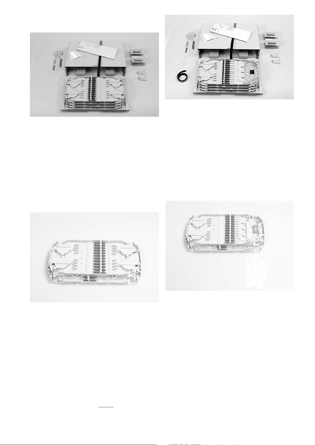
2.1.1 Patch cord IN - patch cord OUT
(example: FIST-GPS2-J-AAA-4)
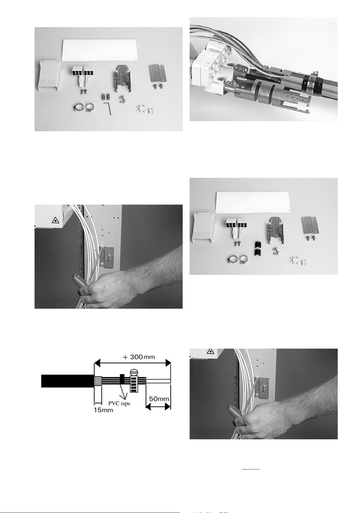
1 unit, incorporating
• metal chassis with drawer
• hingable metal front cover
• hinge and Velcro strap for installation of GPST-12 trays
• 2 pigtail horns
• 2 tray support wedges
• 4 GPST-12 trays
• cage-nuts and bolts
• mounting brackets + screws
• installation instructions
• ID labels
2.1.3 Loose Tube/preconnectorized IFC IN- patchcord OUT
(example: FIST-GPS2-J-AIA-4)
1 unit, incorporating
• metal chassis with drawer
• hingable metal front cover
• hinge and Velcro strap for installation of GPST-12 trays
• 2 pigtail horns
• 2 tray support wedges
• 4 GPST-12 trays, prefibered
• cage-nuts and bolts
• mounting brackets + screws
• tie wraps + adhesive foam
• installation instructions
• ID labels
2 General
2.1 Kit contents
2.1.4 GPST-12 tray configuration:Patch/splice
(Loose Tube and preconnecterised IFC cable)
(example: FIST-GPST-12-AIA-2)
• Tray with 1x pigtail and 1x Splice Unit with splice holder for
12 SMOUV-02 (45 mm)
• 12 Connector adaptors and pigtails per tray
(no pigtails in case of IFC)
• Always delivered in sets of 2 complementary pieces
2.1.2 GPST-12 tray configuration: (Patch only)
(example: FIST-GPST-12-AAA-2)
• Tray with 2x pigtail Unit
• Always delivered in sets of 2 complementary pieces
• 12 connector adaptors
Page 3
3
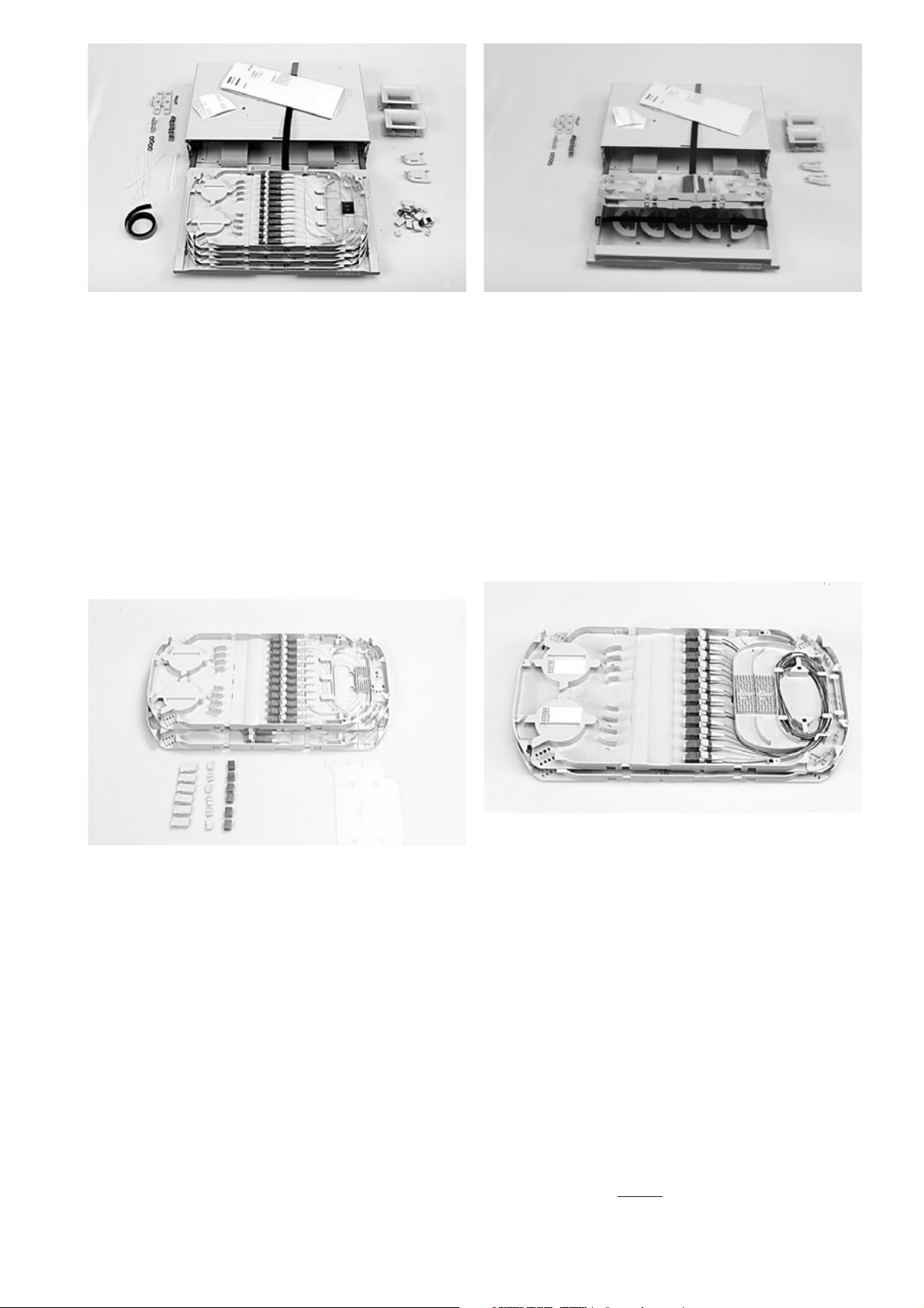
2.1.5 Non-preconnectorized break-out cable IN-patchcord
OUT (example: FIST-GPS2-J-AKA-4)
1 unit, incorporating
• metal chassis with drawer
• hingable metal front cover
• hinge and Velcro strap for installation of GPST-12 trays
• 2 pigtail horns
• 2 tray support wedges
• 4 GPST-12 trays
• cage-nuts and bolts
• 12 GTU(Group Termination Unit)
• mounting brackets + screws
• installation instructions
• ID labels
• Tie wraps + adhesive foam
2.1.6 GPST-12 tray configuration:(Patch/splice)
(Breakout cable) (Example: FIST-GPST-12-AKA-2)
• Tray with 1x pigtail and 1x Splice Unit with splice holder for
12 SMOUV-02 (45 mm)
• 12 connector adaptors and pigtails per tray
• 3 GTU’s (Group Termination Unit) per tray
• Always delivered in sets of 2 complementary pieces
2.1.7 Shelf with storage
(example: FIST-GPS2-J-AAN-T)
1 unit, incorporating
• metal chassis with drawer
• hingable metal front cover
• hinge and Velcro strap for installation of GPST-12 trays
• 2 pigtail horns
• 2 tray support wedges
• storage basket
• max. 2 GPST-12 trays
• cage nuts and bolts
• mounting brackets + screws
• installation instructions
• ID labels
2.1.7 GPST-12 tray configuration : Patch / splice
FIST-GPST-12-AML1-2 (24 pigtails/tray)
• Tray with 1x patch and 1x Splice Unit with splice holder for
24 SMOUV-02 (45 mm)
• 12 connector adapters and 24 pigtails per tray
• 24 SMOUV (splice protector) per tray
• Always delivered in sets of 2 complementary pieces
Page 4
4
3 Installation
3.1 Mounting of shelf in the rack
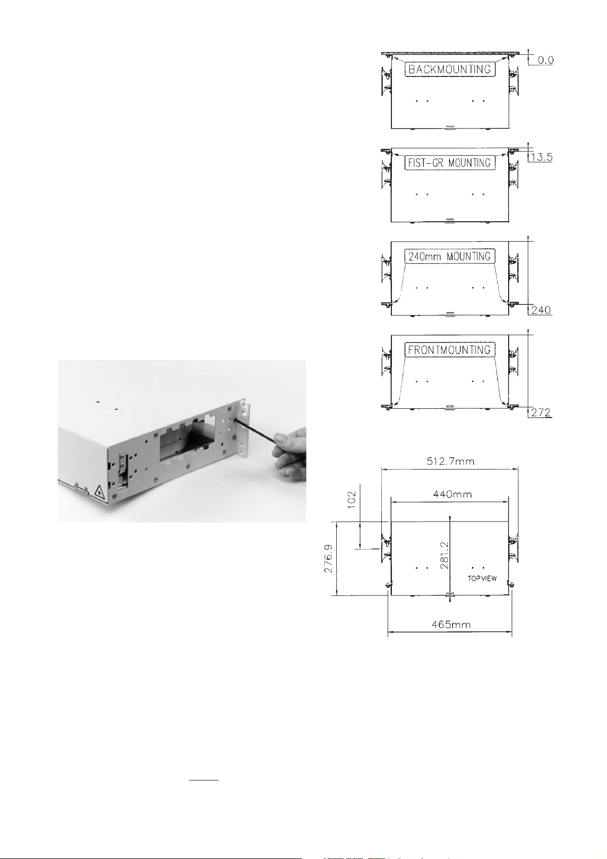
3.1.1 Install the mounting brackets on the correct position. Respect
correct orientation. GR mounting is shown.
3.1.2 Different mounting positions.
2.2 Tools required for installation
• FACC-ALLEN-KEY-5-350 To mount the shelf in the rack
• FACC-CAGE-NUT-TOOL For easy installation of cage nuts
in the rack
• FACC-TUBE-STRIPPER-02 Loose tube stripper
• FISTV-E7170-0003-S5027 Marker pen
2.3 Optional extras*
FIST-UST-... * Side cable termination unit (max. 2 cables)
FIST-CT-2HU-B-2 Back cable termination unit (max. 2 cables)
FIST-MB2-2HU-M Adaption bracket 19”- ETSI (2 pcs)
FIST-MB2-2HU-M-AS Adaption bracket 19”-ETSI asymmetric (1 pc)
FISTV-E7187-6316 Velcro rolls for pigtail
SMOUV-1120-02 45 mm SMOUV fusion splice protections
FIST-TUBE-5MM-30 5 mm tubing
FIST-GS-FLEX-12-50 Flexible tubing, internal Ø 12 mm, 50 m
FIST-GR-TD-5MM Tube divider 6 IN/OUT (for GR)
FIST-GPS2-TD-5MM Tube divider 6 IN/OUT (use in GPS2)
FSA-ADK-... * Various connector mating adaptor kits
FSA-... * Various optical jumpers and pigtails
* see appropriate ordering guide
Page 5
5
3.1.4 Determine the position of the shelf (see rack installation
instruction). Fix the cage nuts into the rack mounting uprights (use the
FACC-CAGE-NUT-Tool).
3.1.6 In case of mounting 19" shelves in ETSI rack: mount the
adaption brackets (FIST-MB2-2HU-M).
3.1.5 Mount the shelf using the FACC-ALLEN-Key.
3.1.3 Space requirements
1 minimum 60 mm at left/right for horn and IFC or pigtails.
2 minimum 60 mm at left /right in case of cable side termination.
3 minimum 45 mm at back in case of cable back termination.
Spacing between adjacent units may vary depending on frame upright
pitch and cable management products!
3.2 Preparation of the shelf
3.3 Preparation of the trays
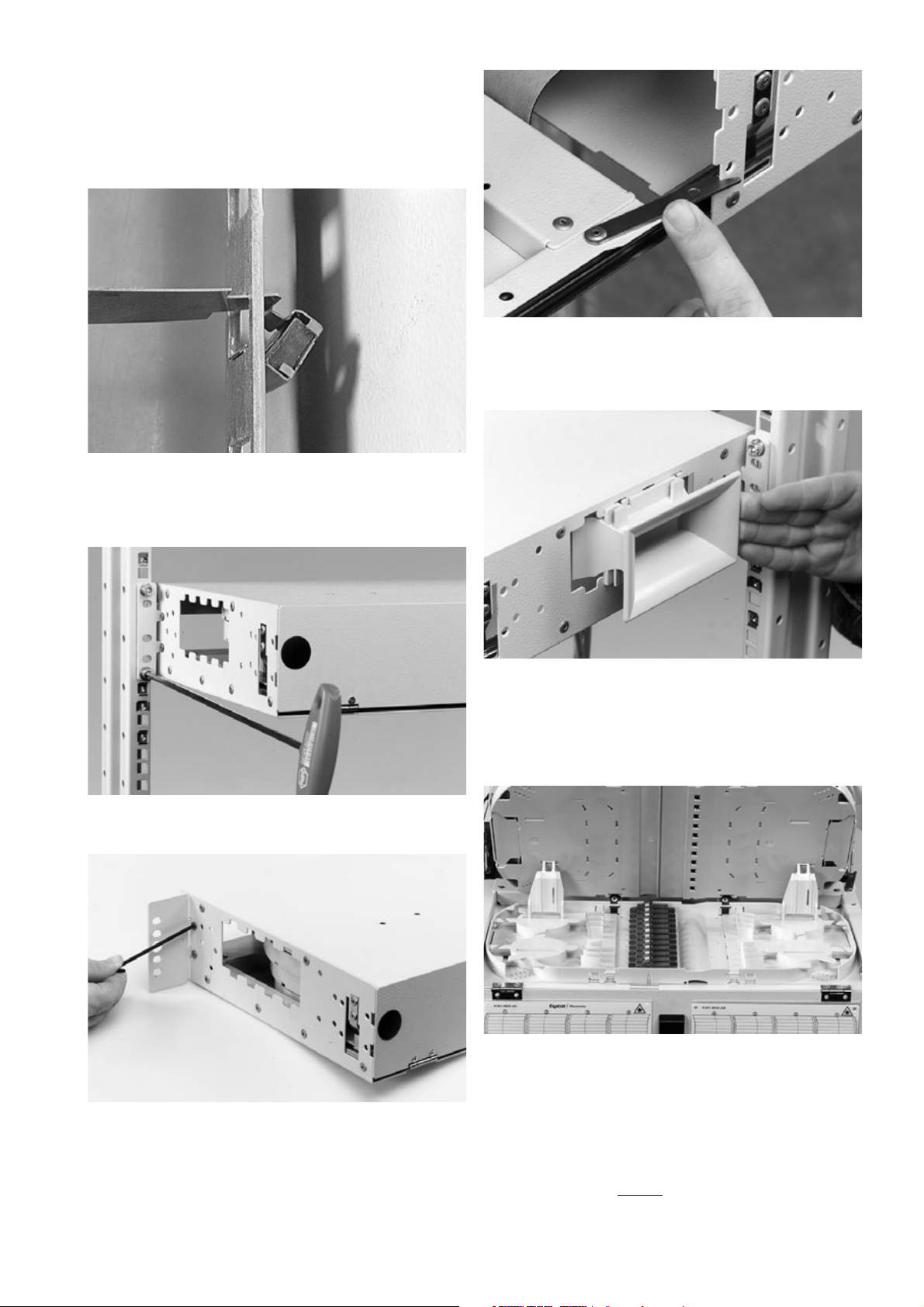
3.2.1 Pull the drawer to the fully open position and rotate the
security-lip 180° to prevent the drawer from moving back inside the
unit.
3.2.2 A trumpet is needed at the side where the pigtails are entering
the shelf. Slide the trumpet in the side panel. Make sure the smallest
side of the trumpet is inside the shelf.
3.3.1 To make a tray accessible raise all the trays above. Keep these
in position by using two tray wedges. Make sure that the bottom tray
has the adaptors positioned at the left side.
Page 6
6
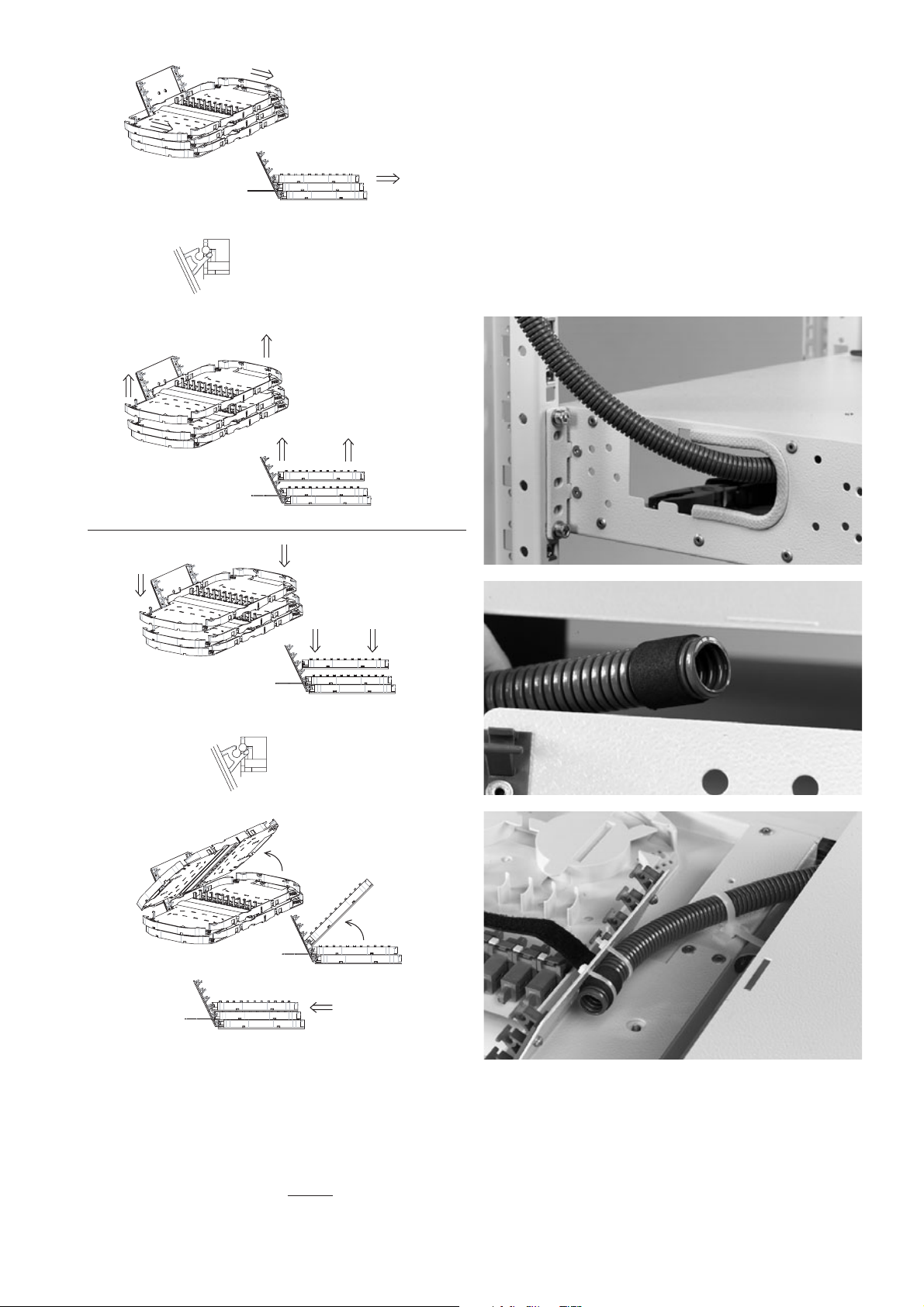
3.3.2 All trays can easily be inserted or removed.
2
1
"CLICK"
OR
2
1
"CLICK"
"CLICK"
"CLICK"
OUT
IN
4 Cable termination
4.1 Cable termination in the rack
Cable is already terminated in the rack or in the side duct of the rack on
the cable termination plate. For the loose tube cable the tubes are
protected from the cable termination plate with the flex tube. For
central core cable, fibers are guided into guiding tubes (5 mm) who go
direct into the shelf.
A Loose tube cable (single fiber)
4.1.1 Cut a flex tube to length according the cable position in the
rack and remove the cable jacket according this length. Make sure you
have 2 m of loose tube inside the shelf.
4.1.2 Make sure the flex tube is long enough so that the drawer
slides easily in and out. Fix the flex tube with tie wrap and foam as
shown on the picture. The knobs of the tie wraps must be positioned at
the front of the metal hinge plate.
Page 7
7
B Loose tube ribbon cable
C Central core cable
4.1.3 Kit content FIST-GR-CTB100 (loose tube ribbon)
• Breakout device + screws
• Breakout device cover + screws
• Cable bracket + screws
• Mounting bracket + washers + screws
• 2 cable clamps
• Unraveling tool
• 2 strength member terminations + screws
4.1.4 Choose a position in the side duct or on the cable termination
plate, close to the shelf. Mount the mounting bracket on that position
with the 2 screws.
4.1.8 Choose a position in the side duct or on the cable termination
plate, close to the shelf. Mount the mounting bracket on that position
with the 2 screws.
4.1.5 Loose tube ribbon cable.
4.1.6 In case of loose tube cable: position the strength member at
the bottom. Bundle the loose tubes with tape. Secure the strength
member with the screws. Continue with installation from paragraph
4.1.15.
4.1.7 Kit content FIST-GR-CTB100CC (central core ribbon)
• Breakout device + screws
• Breakout cover device + screws
• Cable bracket + screws
• Mounting bracket + screws
• 2 cable clamps
• Unraveling tool
• 2 strength member stops + screws
Page 8
8
4.1.9 Central core ribbon cable.
Prepare the cable. Make sure you have 1,5 m of ribbon fiber on the
tray. Respect dimensions shown on the drawings. Clean the fibers very
well to make easy feeding possible.
4.1.13 If extra split-out is needed the tube divider FIST-GPS2-TD-5MM
can be mounted in the shelf. Assemble the tube divider as shown.
Remove the Velcro strip from the shelf and mount it on the cover.
4.1.10 Mount the cable bracket with 2 screws on the mounting
bracket and place the breakout device on the cable bracket.
4.1.11 Loosen the screw of the strength member stop. Rotate the
stop and position the strength members inside.
4.1.12 Secure with the cable clamp. Don’t squeeze the cable.
Page 9

9
4.1.14 The tube divider FIST-GR-TD-5mm can be mounted in the rack.
Install as shown. IN: maximum 6 tubes. OUT: maximum 6 tubes
4.1.15 Remove twists in the ribbons.
a) If ribbons are according ITU norms: use the unraveling device.
The numbers indicate the number of ribbons you want to bundle
(3-4-5 or 6). 3 sizes of ribbon can be handled: ribbon 12, 8 and 4
(3 groove sizes).
b) In other cases use local practice.
4.1.16 Slide the tool over the ribbons. Bundle at the end using Teflon
tape (bundle in groups as you want to feed them through the tubes).
Remove the unraveling device.
4.1.17 Mount the tube divider (if needed) on the metal tray. Cut the
tubes coming from the break-out device to length. Remove the tube
divider to have better access to split out the ribbons.
4.1.18 Insert the tubes in the connectors. Use 6 positions at the left
when cable is mounted at the left side of the bracket. Feed the fiber
groups in the tubes. Start at the back to have easy access. Avoid
crossings of the fibers.
Page 10

10
4.1.19 Slide the cover over the break-out and secure with the screws.
D IFC Cable
4.1.20 Feed the IFC through the trumpet and guide each IFC to the
rear entrance of the tray.
4.2.2 Kit contents
• 1 metal plate
• 2 strength member connectors + screws
• 1 flexible tube (predefined length)
• 3 bolts and nuts
• 4 releasable tie-wraps
• 2 tube clips + lid
• 1 edge protection
• 1 foam strip
• 2 tie-wraps
• 1 tube holder bracket
4.2 Side cable termination directly on the shelf
4.2.1 The cable can be terminated on the shelf: cable terminations
are suited for max. 2 cables, cable retention with tie-wraps, the loose
tubes are fed through a flexible tube to the shelf, the strength member
is attached to the plate.
A Loose tube cable
4.2.3 The picture shows left side mounting and cable coming from
bottom, for right side mounting or cable coming from top a different
assembly is required. Mount the side termination plate onto the shelf
and mount the edge protection.
Page 11

11
4.2.4 Install the flex tube holder on the bracket.
4.2.5 Install the prepared flex tube holder on the shelf.
4.2.6 Install the second flex tube holder.
4.2.7 Fasten the flex tube (before trays are inserted) at the back of
the metal hinge plate using 2 small tie-wraps and fix the flex tube with
a third tie-wrap to the platform. Assure that tie-wraps are well
tensioned to avoid slippage of the tube and cut the excess length of the
tie-wraps. Knobs of the tie-wraps must be positioned at the FRONT of
the metal hinge plate.
4.2.8 Remove the cable jacket over approximately 2.2 m. Wait to
strip the loose tube to avoid fiber breakage. Cut the strength member
to length (l = max. 60 mm).
l
4.2.9 Guide the identified loose tubes into the flex tube. This can be
facilitated by keeping the end of the loose tubes bundled together with
a piece of tape.
Page 12

12
4.2.10 First fasten the flex tube at the bottom tube holder and
afterwards at the top tube holder.
4.2.11 Fasten the strength member connector. Avoid unnecessary
crossing of strength member and loose tube. Attach the cable with the
releasable tie wraps. Note the correct orientation of the tie wraps.
Mount the cover on the flex tube holder.
4.2,12 For cable coming from top use a reverse assembly.
4.2.14 In case of IFC: remove X = 800 mm of outer jacket.
The recommended length of secondary fiber L = 1250-1500 mm.
4.2.13 Kit contents
• 1 metal plate
• 2 strength member connectors + screws
• 1 drum
• 3 bolts and nuts
• 4 releasable tie-wraps
• 1 edge protection
• 1 foam strip
• 2 tie-wraps
• 2 clips
B IFC cable
Page 13

13
4.2.15 Install the edge protection at the bottom of the opening.
Mount the drum on the side panel. Cut the strength member to 60 mm
maximum. Attach the strength member and install as shown.
4.3 Back cable termination directly on the shelf
4.3.1 Cable terminations are suited for 2 cables, max. 3, cable
retention with tie-wraps. Loose tubes are fed through a flexible tube to
the shelf, the strength member is attached to the plate.
In case of IFC no flex tube is used (see point 4.3.10).
4.3.2 Kit contents
• 5 releasable tie-wraps
• 2 strength member connectors + screw
• 1 flexible tube
• 1 tube clip + lid
• 3 bolts & nuts
• 1 foam strip
• 2 tie-wraps
• 1 metal plate
4.3.3 Assemble the components onto the termination plate. The
picture shows cable coming from the left (seen from the back), for
cable coming from right the reverse assembly is required.
X = 80 mm.
4.3.4 Apply 1 layer of foam tape around the flex tube at
approximately 10 mm from the end. This foam tape must be positioned
underneath 1 of the tie-wraps (this tape prevents easy pull-out of the
flex tube).
X = 80 mm
4.3.5 Fasten the flex tube (before trays are inserted,or remove trays)
at the back of the metal hinge plate using 2 small tie-wraps and a third
tie-wrap to the platform. Assure that tie-wraps are well tensioned to
avoid slippage of the tube and cut the excess length of the tie-wraps.
Knobs of the tie-wraps must be positioned at the front of the metal
hinge plate.
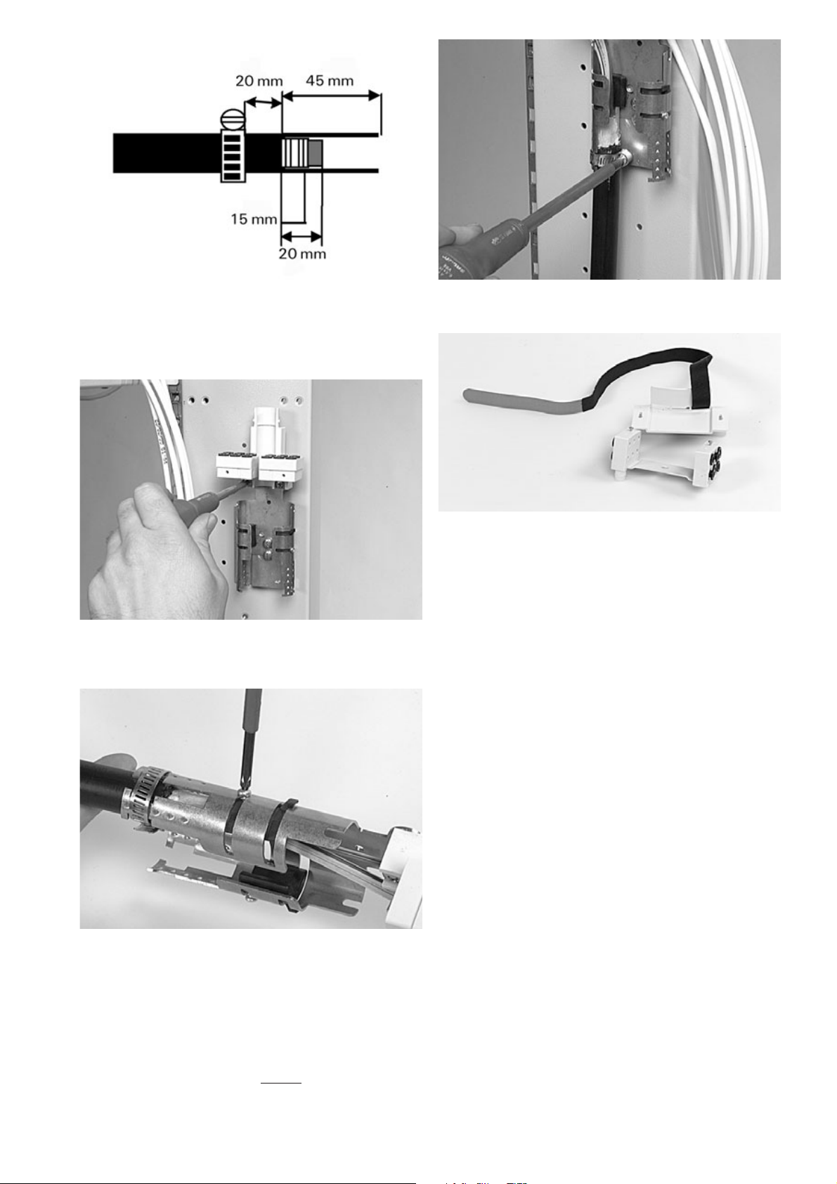
4.3.6 Remove the cable jacket over approximately 2 m. Wait to strip
the loose tube to avoid fiber breakage. Cut the strength member to
length (L = max. 60 mm) and fasten the strength member connector
with the Allen key.
l
A Loose tube cable
Page 14

14
4.3.7 Guide the identified loose tubes into the flex tube. This can be
facilitated by keeping the end of the loose tubes bundled together with
a piece of tape. Make a loop with the flexible tube behind the shelf and
fix the flex tube into the clip of the termination plate.
4.3.8 Attach the strength member connector to the back
termination plate using a Philips screwdriver. Avoid unnecessary
crossing of strength member and loose buffer tubes. Attach the cable
with the releasable tie wraps on the outer jacket. Mount the cover on
the flex tube holder.
B IFC cable
4.3.9 In case of IFC: remove X = 700 mm of outer jacket. The
recommended length of secondary fiber L = 1250-1500 mm.
l
4.3.10 Cut the strength member at l = 60 mm maximum. Attach the
strength member fixation and install as shown.
5 Fiber routing
5.1 Splicing of loose tube on the tray
12 splice module
5.1.1 Identify the loose tubes and put the tie wraps in position on the
tray as shown.
5.1.2 Bring the loose tubes on the tray and mark them at the first
tie-wrap.
Page 15

15
5.1.3 Cut a rubber foam to length and tape it around the loose tube.
5.1.4 Push the loose tubes in the tray and mark them again 15 mm
beyond the second tie wrap.
5.1.5 Strip the loose tubes at this second mark, clean the fibers and
tighten the tie-wraps. Make sure the tie wrap knob is at the side of the
tube.
5.1.6 If necessary, tubes can be bundled with 1 foam. If loose tubes
are added at a later date, use other positions.
5.1.7 If applicable remove all the premounted pigtails out of the
storage area and mark the fibers at the splice holder. Remove the
secondary coating from this point. This assures the transition primary-
secondary is in a straight line!
5.1.8 Position all the pigtails under the splice protection and leave
them there. The fibers have to be kept in this position during further
installation.
5.1.9 Splice the fibers.
Page 16

16
5.1.10 Place the splice protector in the holder, start at outside of the
tray, (hold the splice holder with finger to prevent bending) and coil the
fibers in the tray.
112
5.1.11 Check whether all fibers are properly routed before placing the
cover on the tray. All fibers should be under the containment lips.
24 splice module
5.1.12 Strip the loose tubes and place 1 layer of foam around all the
tubes at 50 mm from the end of the tubes.
5.1.13 Secure all the tubes with the two tie-wraps as shown.
In case not all fibers will be installed at day 1
5.1.16 Secure the added tubes also with one tie-wrap as shown.
Preparation is the same as the first installed tubes.
5.1.14 Strip the loose tubes and place 1 layer of foam around the
tubes at 10 mm from the end of the tubes.
5.1.15 Secure all the tubes with one tie-wrap as shown.
Page 17

17
5.1.17 The split transition plate (1) separates the incoming fiber and
the 900 micron coming from the patchpannel. Strip the 900 micron
somewhere in the middle of the groove. Stripping should always be in
a straight line.
24
1
5.2 Installation of break-out cable on the tray
5.2.1 Use the GTU kit for the termination of a group of 4 pigtails.
5.2.2 Identify the 4 pigtails. Bundle them with PVC tape. Route them
up to the tray, mark the 4 pigtails on the GTU position. Make sure there
is 1,5 m pigtail available from this point. The length is limited to 1 m in
case of tight coated pigtail.
5.1.18 Splicing and storage.
Page 18

18
5.2.3 Strip the pigtail jacket at the marks. Cut the Kevlar to ± 10 cm.
5.2.4 Bend the Kevlar over the edge of the inner part. Don’t entangle
the fibers, avoid crossings.
5.2.5 Slide the outer part over the inner part. Keep both parts under
a certain angle as shown. Keep the Kevlar in position with your left
thumb.
5.2.6 Slide the metal clip over the pigtails and then over the GTU, up
to the front.
5.2.7 Take the GTU at the metal clip and pull at the Kevlar until it
locks completely.
5.2.8 Cut excess Kevlar. Identify the pigtails. Remove the secondary
coating 10-20 mm from the GTU (only possible in case of semi-tight
pigtail). This ensures you the transition primary-to-secundary is in a
straight line.
5.2.9 In case of pigtails with a limited amount of Kevlar (typical
outside diameter < 2.2 mm): wrap the Kevlar twice around the inner
part. Bring the Kevlar of 2 neighbouring pigtails together and pass the
Kevlar between both pigtails. Repeat for the 2 other pigtails. Always
install 4 pigtails.
Page 19

19
5.2.10 Mount the GTU. Start at outside of the tray.
5.2.11 Strip the pre-mounted pigtails (see 5.1.7-5.1.8).
5.2.12 Splice the fibers. Place the splice protector in his holder, start
at outside of the tray. (hold the splice holder with finger to prevent
bending). Coil the fibers in the tray.
1
12
5.2.13 Check wether all fibers are properly routed before placing the
cover on the module. Fibers can not be on top of containment lips.
5.2.14 Remark: storing non spliced fibers.
When not all 12 fibers are spliced at once: route the non-spliced fibers
on top of the stored fibers. Route them outside the storage zone to
have easy access at a later date, without disturbing active circuits.
1
3
2
5.3.1 For ease of installation start with the bottom tray. If possible
apply 1 wrap of foam tape around the IFC, just before the jacket end
(This foam prevents from easy pull-out and provides protection to the
fibers inside). Attach to the tray with 2 small tie-wraps. At least 1 tie-
wrap should be on top of the foam tape. Cut the excess length of the
tie-wrap. Make sure the tie wrap knob is at the side of the IFC. Don’t
squeeze the fibers.
5.3.2 For IFC and pigtail management, leave sufficient slack so that
the drawer can still be opened.
5.3.3 Plug the connectors into the appropriate connector adaptors.
5.3.4 Now the IFC can be coiled into the slack fiber storage area.
Fibers must be untangled before coiling.
5.3 Installation of IFC cable on the tray
12 splice module
Page 20

20
5.4.1 Fix the tubes in the middle position with tie-wraps. Don’t
squeeze the tubes.
5.3.6 Check wether all fibers are properly routed before placing the
cover on the IFC module. All fibers should be underneath the
containment lips.
24 splice module
5.3.7 You can separate each bundle of 900 micron by the split
transition plate (1).
1
1
5.3.8 Install the connectors of the first bundle (1) in the adapters and
then route the overlength in the storage area. Repeat this for the
second bundle (2). Enter the storage area (see picture above).
5.4 Installation of ribbon cable on the tray
5.3.5 Splicing repair connectors is possible : one can use the splice
holder which is premounted in the tray.
Page 21

21
5.4.2 Make the splices and store the overlength without twists in the
storage area.
5.5 Installation of ribbon pigtail on the tray
5.5.1 Route the ribbon to the splicing shelve (GSS2) and make the
splice. Connect the patchcords at the other side (position 1 and 2 is
shown).
6 Storage
6.1 Storage can be done at the bottom of the shelf. Secure with
the Velcro.
6.3 PATCH-SPLICE: storage of a patch cord entering the shelf at
the right side is shown. Check the position of the smalll bend control.
6.4 In case of patch cords entering at the left-hand side: position
the small bendcontrol at the right side.
6.2 PATCH-PATCH: storage of a patch cord entering the shelf at
the right side is shown. Check the position of the small bendcontrol.
Page 22

22
7.1 Route the jumper through the horn up to the tray. Remove the
connector adaptor out of the tray and mount the connector into it as
described. Push the plastic hooks which hold the adaptor away(1) and
push the adaptor simultaneously in the opposite direction(2). Place the
adapter + connector back in the tray by sliding and hinging it down
along the vertical axis.
7 Patching
7.2 Repeat this procedure with the other pigtails. Respect routing
of jumpers as shown on the picture. Provide sufficient slack for
patching to all other positions in the shelve.
7.3 Routing of incoming pigtails and outgoing patchcords.
Page 23

23
8.1 Place the labels and write down information.
8.2 Picture showing all the available labels for identification.
8 Closing
8.3 Place the tray wedges on the velcro and secure the trays with
the velcro. Close the drawer after turning the security clip 180° and by
pushing the spring on the right side of the shelf.
8.4 Identification of the shelf and the trays.
8.5 Write down information on the ID-cards.
9 Important steps
• In case of loose tube termination side or back:
- don't modify the predefined flex tube length;
- apply foam tape to the flex tube;
- apply foam tape to loose tubes.
• Make sure the transition primary-to-secondary fiber is in a straight
line: under the splice holder (in case of tight coated pigtail: in the
splice protector).
• Cut excess length of tie-wraps.
• Make sure all fibers and pigtails are properly routed and are under
the containment lips.
• Bundle pigtails/patch cords with velcro; don’t use tie wraps.
• Try to store ribbons without twists.
Page 24

24
TC 634/IP/2 12/04
The information given herein, including drawings, illustrations and schematics which are intended for illustration purposes only, is
believed to be reliable. However, Tyco Electronics makes no warranties as to its accuracy or completeness and disclaims any liability
in connection with its use. Tyco Electronics’ obligations shall only be as set forth in Tyco Electronics’ Standard Terms and Conditions
of Sale for this product and in no case will Tyco Electronics be liable for any incidental, indirect or consequential damages arising out
of the sale, resale, use or misuse of the product. Users of Tyco Electronics products should make their own evaluation to determine
the suitability of each such product for the specific application.
Tyco Electronics Raychem NV
Telecom Outside Plant
Diestsesteenweg 692
B-3010 Kessel-Lo, Belgium
Tel.: 32-16-351 011
Fax: 32-16-351 697
www.tycoelectronics.com
Tyco and FIST are trademarks. Kevlar is a trademark of E.I. du Pont de Nemours. Velcro is a trademark of Velcro Industries B.V.
 Loading...