

Page 1

TYCO ELECTRONIC PRODUCT GROUP PAGE 1 OF 1
F08 INSTALLATION & PROGRAMMING MANUAL
DOCUMENT DATA SHEET
DO NOT PRINT
Document Number LT0082
Document Title F08 Installation & Programming Manual
Manual Volume 1
Word Processor Word 2000
File Name
G:\CH_TSP_All Staff\VIGDOCS\MANUALS\F08\LT0082 Iss 3.04.DOC
Printer HP Laserjet 4M Plus
Current Issue Issue 3.04, 24 March 2006
LT0082 Issue 3.0 Amendment 0
Prefix
Chapter 1 : Introduction
Chapter 2 : FIP Installation
Chapter 3 : Placing into Operation
Chapter 4 : Programming
Chapter 5 : Application Considerations
Appendix A1 : Compatible Batteries
Appendix A2 : Compatible Actuating Devices
Appendix A3 : Installation Drawings
Zone Designation Label
PRINTING SPECIFICATIONS
1. Paper Type: 80gsm Bond White
2. Manual Size: A4
3. Place in 4-ring binder
Front and spine inserts to be fitted with labels stating:
LT0082
TYCO F08
INSTALLATION & PROGRAMMING
5. All pages are double sided, except for the diagrams at the end of the manual.
Chapter 0
Chapter 1
Chapter 2
Chapter 3
Chapter 4
Chapter 5
Appendix A1-3
6
4
34
8
24
14
6
=
=
=
=
=
=
=
3
2
17
4
12
7
3
double-sided
double-sided
double-sided
double-sided
double-sided
double-sided
double-sided
96 48
Drawings + 5 single-sided
Page 2

F08 Installation & Programming Manual Document No: LT0082
THIS PAGE INTENTIONALLY LEFT BLANK
Page ii 24 March 2006 Issue 3.04
Page 3

F08
INSTALLATION & PROGRAMMING
MANUAL
F08 PRODUCT MANUAL
DOCUMENT: LT0082
Issue 3.04; 24 March 2006
The F08 Fire Indicator Panel is manufactured for
Tyco Services Fire & Safety
47 Gilby Road
Mt Waverley
VIC 3149
AUSTRALIA
Tel : +61-3-9538 7220
Fax : +61-3-9538 7255
COPYRIGHT (C) 2002
Information contained in this document is copyright, and shall not be reproduced in any form whatsoever,
or its contents disclosed to any third party, without the written consent of Tyco Services Fire & Safety (The
Company). Information contained in this document is believed to be accurate and reliable, however the
company reserves the right to change the content without prior notice.
Page 4

F08 Installation & Programming Manual Document No: LT0082
NON-DISCLOSURE AGREEMENT
Tyco Services Fire & Safety (THE COMPANY) and the User of this/these document(s)
desire to share proprietary technical information concerning electronic systems.
For this reason the company is disclosing to the User information in the form of this/these
document(s). In as much as the company considers this information to be proprietary and
desires that it be maintained in confidence, it is hereby agreed by the User that such
information shall be maintained in confidence by the User for a period of TEN YEARS after
the issue date and only be used for the purpose for which it was supplied.
During this period, the User shall not divulge such information to any third party without the
prior written consent of the company and shall take reasonable efforts to prevent any
unauthorised disclosure by its employees. However, the User shall not be required to keep
such information in confidence if it was in their possession prior to its receipt from the
company; if it is or becomes public knowledge without the fault of the User; or the
information becomes available on an unrestricted basis from a third party having a legal right
to disclose such information.
The User's receipt and retention of this information constitutes acceptance of these terms.
This information is copyright and shall not be reproduced in any form whatsoever.
END USER LIABILITY DISCLAIMER
The F08 Fire Indicator Panel provides a configuration programming facility which may be
accessed via a programming push-button. Because this programming facility allows the user
to define in detail the operation of the F08 System, changes may be made by the user that
prevent an installation from meeting statutory requirements.
The Company, therefore cannot accept any responsibility as to the suitability of the functions
generated by the user using the programming facility of the F08.
* * WARNING * *
The F08 is approved to AS/NZ 3548 Class A.
In a domestic environment it may cause radio interference, in which case the user
may be required to take adequate measures.
Page ii 24 March 2006 Issue 3.04
Page 5

Document No: LT0082 F08 Installation & Programming Manual
TABLE OF CONTENTS
NON-DISCLOSURE AGREEMENT......................................................................................ii
END USER LIABILITY DISCLAIMER...................................................................................ii
AMENDMENT LOG..............................................................................................................v
1. INTRODUCTION ............................................................................................................. 1-1
1.1 USING THIS MANUAL............................................................................................. 1-2
1.2 ASSOCIATED DOCUMENTATION.......................................................................... 1-3
1.3 TERMINOLOGY ....................................................................................................... 1-4
2. FIP INSTALLATION........................................................................................................ 2-1
2.1 OVERVIEW............................................................................................................... 2-2
2.2 CABINET INSTALLATION....................................................................................... 2-3
2.3 MAINS WIRING ........................................................................................................2-6
2.4 MAIN BOARD........................................................................................................... 2-8
2.5 BATTERY INSTALLATION.................................................................................... 2-11
2.6 FIP MCP WIRING ................................................................................................... 2-12
2.7 ALARM ZONE WIRING & CIRCUIT TYPES.......................................................... 2-13
2.8 BELL OUTPUT WIRING......................................................................................... 2-18
2.9 ANCILLARY RELAY OUTPUT WIRING................................................................ 2-26
2.10 AUXILIARY OUTPUT WIRING........................................................................... 2-28
2.11 DOOR HOLDER WIRING ................................................................................... 2-29
2.12 BRIGADE INTERFACE RELAYS....................................................................... 2-30
2.13 DISPLAY & ZONE LABELLING......................................................................... 2-34
2.14 DOCUMENTATION............................................................................................. 2-35
3. PLACING INTO OPERATION......................................................................................... 3-1
3.1 GENERAL................................................................................................................. 3-2
3.2 MAINS ISOLATE SWITCH....................................................................................... 3-2
3.3 POWER UP............................................................................................................... 3-4
Issue 3.04 24 March 2006 Page iii
Page 6

F08 Installation & Programming Manual Document No: LT0082
3.4
COMMISSIONING CHECKLIST............................................................................... 3-6
4. PROGRAMMING............................................................................................................. 4-1
4.1 PROGRAMMING FEATURES.................................................................................. 4-2
4.2 ENTERING PROGRAMMING MODE....................................................................... 4-5
4.3 EXITING PROGRAMMING MODE........................................................................... 4-6
4.4 RESET TO DEFAULT PARAMETERS .................................................................... 4-7
4.5 PROGRAMME ZONE TO OUTPUT MAPPING........................................................ 4-8
4.6 PROGRAMMING ZONES AS LATCHING OR NON-LATCHING.......................... 4-12
4.7 PROGRAMMING ZONE INPUT TYPE................................................................... 4-14
4.8 ENABLING OR DISABLING ZONES..................................................................... 4-16
4.9 PROGRAMMING ANCILLARY RELAY SUPERVISION........................................ 4-18
4.10 PROGRAMMING ZONE AUXILIARY OUTPUT MODE...................................... 4-20
4.11 EXIT PROGRAMMING CHECKLIST.................................................................. 4-22
4.12 TROUBLE SHOOTING IN PROGRAMMING MODE.......................................... 4-23
5. APPLICATION CONSIDERATIONS............................................................................... 5-1
5.1 SUB-PANEL WIRING............................................................................................... 5-2
5.2 FIRE DETECTION IN HAZARDOUS AREAS.......................................................... 5-5
5.3 PREVENTION OF NON “FIRE” ALARMS............................................................. 5-10
5.4 TROUBLE SHOOTING........................................................................................... 5-11
APPENDIX A1 - COMPATIBLE BATTERIES.................................................................. A1-1
APPENDIX A2 - COMPATIBLE ACTUATING DEVICES................................................A2-1
APPENDIX A3 - INSTALLATION DRAWINGS ............................................................... A3-1
Page iv 24 March 2006 Issue 3.04
Page 7

Document No: LT0082 F08 Installation & Programming Manual
AMENDMENT LOG
ISSUE DATE AMENDMENT ECN
1 10 Oct 89 Original with two versions:
- Document 696-005 -> Installation
- Document 696-004 Issue 1 -> Programming
Amendment: 1 December 14, 1989
2 11 Apr 92 Combined Installation, Programming and Brigade Kit
Documentation.
28 May 98 Converted to Word 95 document.
3 27 Oct 98 For V3.00 F08 software, additional input types,
RAD/SAD, etc, 15V MCP, Resistor EOL.
2769
3.01
31 Jul 02 Prefix, Pages 2-6, 2-7, 2-27, 5-6….5-12, Appendix A
revised.
3322
3.02 1 Mar 05 Fig 2.12 had Ext Def- directly driving the detector
circuit.
Appendix A2 - add 614CH, 614I & 614P
3524
3635
3.03 28 Oct 05 Added System Sensor detector 885WP-B to
Appendix A.
ECS
1181
3.04 24 Mar 06 Appendix A2 – added 614T 3731
Issue 3.04 24 March 2006 Page v
Page 8

F08 Installation & Programming Manual Document No: LT0082
THIS PAGE INTENTIONALLY LEFT BLANK
Page vi 24 March 2006 Issue 3.04
Page 9

Document No: LT0082 F08 Installation & Programming Manual
Introduction
1. INTRODUCTION
Issue 3.04 24 March 2006 Page 1-1
Page 10

F08 Installation & Programming Manual Document No: LT0082
Introduction
1.1 USING THIS MANUAL
This Manual provides information for personnel engaged in the installation, programming
and commissioning of the F08 Fire Alarm Panel. It is available only to bonafide installation
and maintenance organisations.
The structure of this manual is as follows:
Chapter 1, Introduction, describes the manual, explains the format and terminology used
in this manual, and lists associated F08 product manuals.
Chapter 2, FIP Installation, describes the installation of the F08 FIP; mains wiring; battery
installation; detector, ancillary, auxiliary, bell and brigade output wiring; and other related
wiring.
Chapter 3, Placing Into Operation, describes the procedures for placing an F08 into
operation. A commissioning checklist is included.
Chapter 4, Programming An F08, describes the steps necessary in programming an F08
FIP ready for a particular installation.
Chapter 5, Application Considerations, describes some aspects of special applications,
such as remote panel operation, false alarm minimization and trouble shooting.
Appendix A1, Compatible Batteries, gives a list of compatible batteries.
Appendix A2, Compatible Detectors, gives a list of detectors compatible with the F08.
Appendix A3, Installation Drawings, Includes wiring diagrams for the various brigade
interfaces and provides a place for system installation drawings to be inserted.
Page 1-2 24 March 2006 Issue 3.04
Page 11

Document No: LT0082 F08 Installation & Programming Manual
Introduction
1.2 ASSOCIATED DOCUMENTATION
1.2.1 PRODUCT RELATED
The following F08 manuals are available:
Volume 1 F08 Operator's Manual, provides a complete guide to the operation and
maintenance of the F08 FIP, according to Australian Standards AS1603 Part
4. This manual is provided as standard with F08 FIP panels. It is available in
a bound A5 format (LT0054) and in an A4 loose-leaf format (LT0078).
Volume 2 F08 Technical Manual, provides complete technical details on the F08
system and Hardware/Software components, according to Australian
Standards AS1603 Part 4, for servicing purposes. (LT0081)
Volume 3 F08 Installation & Programming Manual, provides complete details for
correctly installing, wiring, programming and placing into operation the F08
FIP. (LT0082)
1.2.2 STANDARD RELATED
AS1603.1,2,3 Automatic Fire Detection and Alarm Systems -Detectors Parts 1, 2,
& 3 (Heat, Smoke, & Flame)
AS1603.4 Automatic Fire Detection and Alarm Systems
Part 4 - Control and Indicating Equipment
AS1603.5 Automatic Fire Detection and Alarm Systems
Part 5 - Manual Call Points
AS1603.6 Automatic Fire Detection and Alarm Systems
Part 6 - Fire Alarm Bells and Bell Simulators
AS1670.1 Automatic Fire Detection and Alarm Systems -
System Design, Installation, and Commissioning.
AS1851.8 Automatic Fire Detection and Alarm Systems.
Part 8 - Maintenance of Fire Protection Equipment
Issue 3.04 24 March 2006 Page 1-3
Page 12

F08 Installation & Programming Manual Document No: LT0082
Introduction
1.3 TERMINOLOGY
The following abbreviations and terminology are used in this manual.
A/C : Air Conditioning
"ACVD" : Display abbreviation for ACTIVATED
"ALM" : Display abbreviation for ALARM
Ancillary Equipment : Equipment external to Fire Alarm system
Ancillary Relay : Relay in FIP which operates Ancillary equipment
Auto-Reset : Mode for one man testing of detectors
Auxiliary Output : Output for driving additional outputs
AZC : Alarm Zone Circuit, or Detection Zone
AZF : Alarm Zone Facility, or Group
AVF : Alarm Verification Facility, or Check Alarm
COM : COMMON relay contact
Control Key : Key on FIP Display panel for operator control
Control Output : Output from FIP to other equipment
DETECTOR : Alarm Detec tion Device
DETECTOR CIRCUIT : Detectors electrically connected to FIP
EEPROM : Electrically Eraseable Programmable Read Only
Memory
EOL : End Of Line (device)
ELV : Extra Low Voltage
FIRE CONTROL STATION : Fire Brigade Authority, or any other authority which
receives the FIP alarm signals.
FIP : Fire Indicator Panel
"FLT" : Display abbreviation for FAULT
FRC : Flat Ribbon Cable
GLOBAL : No F08 zone/output/battery selected. (i.e. all "SEL"
LED indicators are OFF)
"ISO" : Display abbreviation for ISOLATED
LED : Light Emitting Diode
MAPPING : Programming AZCs to control outputs
MCP : Manual Call Point (Break Glass Switch)
MOV : Metal Oxide Varistor (Used for Surge Protection)
NC : Normally Closed
NO : Normally Open
PCB : Printed Circuit Board
PTC : Positive Temperature Co-efficient (Thermistor)
RAM : Random Access Memory
ROM : Read Only Memory
"SEL" : Display abbreviation for SELECT
U18.6 : IC U18 pin 6
VB : Battery Backed Voltage.
VNB : Non Battery Backed Voltage.
ZONE : Fire searchable area of building
Page 1-4 24 March 2006 Issue 3.04
Page 13

Document No: LT0082 F08 Installation & Programming Manual
FIP Installation
2. FIP INSTALLATION
Issue 3.04 24 March 2006 Page 2-1
Page 14

F08 Installation & Programming Manual Document No: LT0082
FIP Installation
2.1 OVERVIEW
This chapter describes in detail the following FIP installation procedures:
Cabinet Installation
Mains Wiring
Battery Installation
MCP Wiring
Alarm Zone Wiring & Circuit Types
Bell Output Wiring
Supervised Ancillary Relay Output Wiring
Auxiliary Output Wiring
Door Holder Wiring
Brigade Interface Relays
Zone Labelling.
* * WARNING * *
PLEASE ENSURE THAT THE SYSTEM HAS BEEN THOROUGHLY TESTED BEFORE
THE CONNECTION OF BATTERIES AND EXTERNAL WIRING.
Page 2-2 24 March 2006 Issue 3.04
Page 15

Document No: LT0082 F08 Installation & Programming Manual
FIP Installation
2.2 CABINET INSTALLATION
The location of the F08 FIP is determined by the FIRE AUTHORITY and the OWNER or
OWNERS' REPRESENTATIVE in accordance with the current Australian Standard
AS1670.1.
The cabinet is normally fixed to a wall with four (4) 6 mm screws or bolts. The drilling details
are shown in Figure 2.1.
The following points must be observed.
(a) Dry Area, 50°C maximum ambient temperature.
(b) Not exposed to direct sunlight or external environments without suitable
protection.
(c) Indicators and controls must not be higher than 1850 mm and not lower than
750 mm above finished floor level (see Figure 2.1).
(e) Clear access; easy Fire-Fighter's access and observation.
(f) For unhampered installation and maintenance, at least 1 metre free space
must be provided to the front and sides of the F08 FIP. (see Figure 2.2)
(g) Must not be installed in hazardous areas as defined in AS3000.
(h) If recessed into a wall cavity, allow for the door to open by at least 145° and
prevent water entering the cabinet. Seal unused knockouts and any top cable
entries. Preferably use bottom cable entry, with cables going down 100 mm
below cabinet before rising.
* * WARNING * *
1. It is not necessary to remove the Main Board Electronics when installing the cabinet.
However, if drilling or filing holes in the cabinet, remove the Main board first, and
clean out any swarf before replacing. Refer to Section 2.4.3 for the correct procedure
for removing and refitting the Main Board.
2. Use ANTI-STATIC precautions when handling any PCBs.
Issue 3.04 24 March 2006 Page 2-3
Page 16

F08 Installation & Programming Manual Document No: LT0082
FIP Installation
300
│───────────────────────────────────│
│ │
┌───────────────────────────────────────────┐ ───
│ │ │ │ │ 50
│ │ │ │ │
───────────────│── o ───────────────────────────────── o ──│────
│ │ │6.5 6.5│ │
│ │ │ │ │ │
│ │ │ │ │ │
│ │ │ │ │ │
│ │ │ │ │ │
│ │ │ │ │ │
│ │ │ │ │ │
│ │ │ │ │ │
│ │ │ │ │ │
│ │ │ │ │ │
│ │ │ │ │ │450
│ │ │ │ │ │
│ │ │ │ │ │
│ │ │ │ │ │
│ │ │ │ │ │
│ │ │ │ │ │
│ │ │ │ │ │
│ │ │ │ │ │
│ │ │ │ │ │
│ │ │ │ │ │
│ │ o ───────────────────────────────── o ──│────
│ │ 6.5 6.5 │
│ 1870 (MAX) │ │
│ └───────────────────────────────────────────────┘
│ 870 (MIN)
│
│
│
│
│
│
│
│ ALL DIMENSIONS IN MILLIMETRES
│
│
│
│
│ FINISHED FLOOR LEVEL
▄▄▄▄▄▄▄▄▄▄▄▄▄▄▄▄▄▄▄▄▄▄▄▄▄▄▄▄▄▄▄▄▄▄▄▄▄▄▄▄▄▄▄▄▄▄▄▄▄▄▄▄▄▄▄▄▄▄▄▄▄▄▄▄▄▄▄▄
/ / / / / / / / / / / / / / / / / / / / / / / / / / / / / / / / / /
Figure 2.1
F08 Cabinet Mounting Details
Page 2-4 24 March 2006 Issue 3.04
Page 17

Document No: LT0082 F08 Installation & Programming Manual
FIP Installation
▄▄▄▄▄▄▄▄▄▄▄▄▄▄▄▄▄▄▄▄▄▄▄▄▄▄▄▄▄▄▄▄▄▄▄▄▄▄▄▄▄▄▄▄▄▄▄▄▄▄▄▄▄▄▄▄▄▄▄▄▄▄▄▄▄▄▄▄
│ │
│ │
│ 0.5m │ F08 FIP │ 0.5m │
│ │ │ │
───── ┌──────────── └┬┬──────────────────────┘ ───────────┐
│░░░░░░░░░░░░░░││░░░░░░░░░░░░░░░░░░░░░░░░░░░░░░░░░░░│
│░░░░░░░░░░░░░░││░░░░░░░░░░░░░░░░░░░░░░░░░░░░░░░░░░░│
│░░░░░░░░░░░░░░││░░░░░░░░░░░░░░░░░░░░░░░░░░░░░░░░░░░│
│░░░░░░░░░░░░░░││░░░░░░░░░░░░░░░░░░░░░░░░░░░░░░░░░░░│
│░░░░░░░░░░░░░░││░░░░░░░░░░░░░░░░░░░░░░░░░░░░░░░░░░░│
│░░░░░░░░░░░░░░││░░░░░░░░░░░░░░░░░░░░░░░░░░░░░░░░░░░│
1m │░░░░░░░░░░░░░░││░░░░░░░░░ AS1670 CLEAR AREA ░░░░░░░│
│░░░░░░░░░░░░░░││░░░░░░░░░░░░░░░░░░░░░░░░░░░░░░░░░░░│
│░░░░░░░░░░░░░░││░░░░░░░░░░░░░░░░░░░░░░░░░░░░░░░░░░░│
│░░░░░░░░░░░░░░││░░░░░░░░░░░░░░░░░░░░░░░░░░░░░░░░░░░│
│░░░░░░░░░░░░░░││░░░░░░░░░░░░░░░░░░░░░░░░░░░░░░░░░░░│
│░░░░░░░░░░░░░░└┘░░░░░░░░░░░░░░░░░░░░░░░░░░░░░░░░░░░│
│░░░░░░░░░░░░░░░░░░░░░░░░░░░░░░░░░░░░░░░░░░░░░░░░░░░│
───── └───────────────────────────────────────────────────┘
Figure 2.2
FIP Cabinet Clearance
Issue 3.04 24 March 2006 Page 2-5
Page 18

F08 Installation & Programming Manual Document No: LT0082
FIP Installation
2.3 MAINS WIRING
Mains wiring must be done in accordance with AS1670.1 and AS3000 Wiring Regulations.
* * WARNING * *
Ensure mains is isolated at Distribution Board before connecting or inspecting mains wiring.
The mains wiring should be fixed firmly to the 3 way screw terminal block under the Mains
switch.
Check that safety earths to cabinet doors, Main Board, and mains switch cover are still
connected firmly to the earth studs.
* * NOTES * *
1. Mains supply must be 240 VAC (+6% -10%), at 50 Hz, and terminated as described.
2. All other wiring coming into the panel, including all relay wiring, must only be ELV.
Page 2-6 24 March 2006 Issue 3.04
Page 19

Document No: LT0082 F08 Installation & Programming Manual
FIP Installation
THIS PAGE INTENTIONALLY LEFT BLANK
Issue 3.04 24 March 2006 Page 2-7
Page 20

F08 Installation & Programming Manual Document No: LT0082
FIP Installation
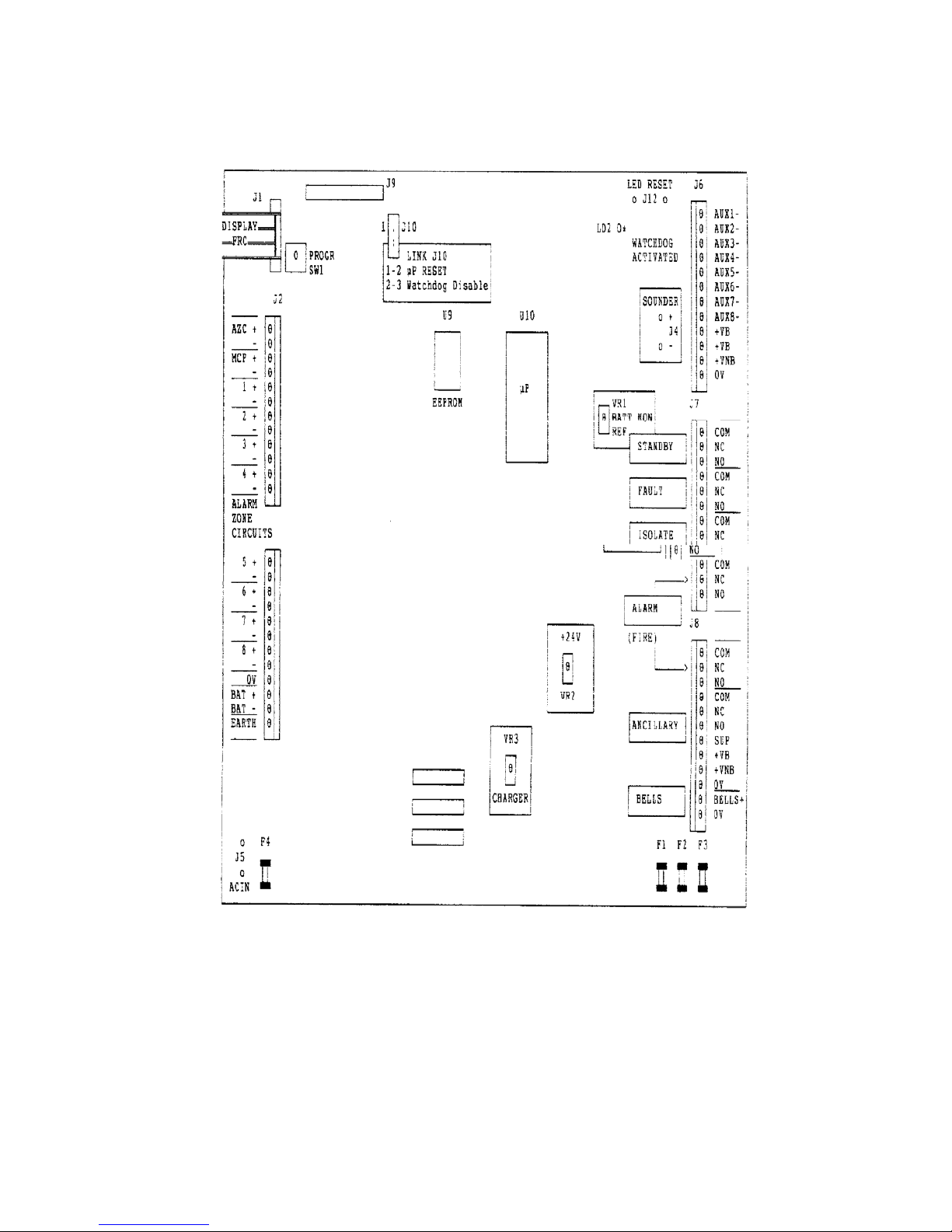
2.4 MAIN BOARD
Figure 2.4 shows the basic layout of the F08 FIP Main Board.
2.4.1 TERMINALS
The following terminals and connectors are provided:
J1 - Display FRC Output Connector.
J2 - 12 Way Screw Input Terminal for MCP AZC, MCP, AZC1, AZC2 and AZC3.
J3 - 12 Way Screw Terminal for AZC4, AZC5, AZC6, AZC7, AZC8, 0V,
BATTERY, and EARTH.
J4 - Sounder Output Connector.
J5 - AC IN - 31 VAC Input Connector.
J6 - 12 Way Screw Terminal for AUX1- to AUX8-, VB, VNB, and 0V.
J7 - 12 Way Screw Terminal for Brigade Relays; Standby, Fault, Isolate and
Alarm.
J8 - 12 Way Screw Terminal for Alarm Relay, Ancillary Relay & Supervision and
Bells.
J9 - Reserved for future MODEM socket.
J10 - Link 1-2 for Microprocessor RESET
Link 2-3 for Watchdog DISABLE.
J12 - Reset Watchdog Activated LED.
2.4.2 FUSES
The following fuses are located on the Main Board:
F1 BELLS Rated 1.6 Amp
F2 VB Rated 1.6 Amp
F3 VNB Rated 1.6 Amp
F4 AC IN 31VAC Rated 5.0 Amp
2.4.3 REMOVAL & INSTALLATION
The Main Bd should be removed carefully as it is a delicate piece of electronic equipment.
An electrostatic earth lead should be worn at all times when working on the bd.
Disconnect all field wiring, battery leads, MCP wiring, AC leads, earth wires and the Display
Bd FRC from the Main Bd. Undo the 3 nuts that secure the heatsink to the cabinet case.
Push back the barbs on the plastic standoffs and carefully pull the Main Bd away from the
cabinet.
DO NOT separate the heatsink from the Main Bd as this will weaken the components on the
heatsink and increase any repair cost.
Installation is just the reverse of the removal.
Thoroughly check the wiring before applying power and check all functions after power is
connected.
Page 2-8 24 March 2006 Issue 3.04
Page 21
Document No: LT0082 F08 Installation & Programming Manual
FIP Installation
Figure 2.4
F08 Main Board Layout
Issue 3.04 24 March 2006 Page 2-9
Page 22

F08 Installation & Programming Manual Document No: LT0082
FIP Installation
2.4.4 FIELD SUPPLY CONNECTIONS
The F08 FIP Main Board provides two types of fused power outputs.
(a) Terminals labelled "+VB" provide 27.3 VDC supply output, which is battery backed.
"+VB" terminals are fused by F2.
(b) Terminals labelled "+VNB" provided a non-battery backed 27.9 VDC supply output.
"+VNB" terminals are fused by F3.
The total load current available from "+VB" and "+VNB" is 1.5 Amps. This excludes the panel
and battery charging currents.
A block diagram of the fused power outputs is shown in Figure 2.5.
FUSE
┌──────┐
┌──────────────┤ F3 ├──────── VNB
│ └──────┘ 27.9 VDC
────────────┐ │ 1.5A
30 VAC │ │
─────────┐ │ │
│ │ │
┌─────┴──┴─────┐ │ FUSE
│ │ │ ┌──────┐
│ REGULATOR ├────┴───┤ ├───┬───┤ F2 ├──────── VB
│ │ │ └──────┘ 27.3 VDC
└──────────────┘ │ 1.5A
2A CURRENT │
LIMITED │
│
│
│
┌──────────────┐ │
│ │ │
│BATTERY 24 VDC├───────────────┘
│ │
└──────────────┘
Figure 2.5
Block Diagram of F08 Power Supply
Page 2-10 24 March 2006 Issue 3.04
Page 23

Document No: LT0082 F08 Installation & Programming Manual
FIP Installation
2.5 BATTERY INSTALLATION
Install only compatible batteries (refer Appendix A) in the bottom of the FIP cabinet. Using
the battery cables supplied, connect wiring as shown in Figure 2.6.
* * NOTES * *
(a) The F08 system should be system tested before connecting the batteries.
(b) If the batteries are located remotely from the F08, a battery protection device
(> 3 Amps) must be located at the batteries.
(c) USE ONLY THE BATT+ & BATT- TERMINALS PROVIDED. PARALLEL
CONNECTION OF BATTERIES IS NOT PERMITTED.
PLEASE OBSERVE POLARITY
│ │Q││ 0V │
│ ├─┤│ │
╔═══╪════╡Q││ BATT + │
║ │ ├─┤│ │
╔══════════╡Q││ BATT - │
║ ║ │ ├─┤│ │
║ ║ │ │Q││ EARTH │
║ ║ │ └─┴┘ F08 MAIN BOARD │
║ ║ ────────────────────────────────────────────────────────────┘
║ ║ ────────────────────────────────────────────────────────────┐
║ ║ │ │
║ ║ │ HEATSINK │
║ ║ │ │
║ ╚════════════════════════════════════════════════════════════════╗
║ ║
║ ┌─────────────┐ ┌───────────┐ ║
║BLACK │ │ │ │ RED║
║ │ │ │ │ ║
║ │ │ │ │ ║
║ │ TRANSFORMER │ │ MAINS │ ║
║ │ │ │ SWITCH │ ║
║ ┌──────────────┐ │ │ │ │ ┌──────────────┐ ║
║ │ ┌─┐ ┌─┐ │ │ │ │ │ │ ┌─┐ ┌─┐ │ ║
║ │ ███ - + ███ │ │ │ │ │ │ ███ - + ███ │ ║
║ │ ███ ███ │ └─────────────┘ └───────────┘ │ ███ ███ │ ║
║ │ ║ ║ │ │ ║ ║ │ ║
║ │ ║ ║ │ │ ║ ║ │ ║
║ │ ║ ║ │ │ ║ ║ │ ║
╚════╝ ╚══════════════════════════════════════╝ ╚════╝
│ │ │ │
│ │ │ │
│ │ │ │
│ BATTERY │ │ BATTERY │
│ 12V │ │ 12V │
│ │ │ │
└──────────────┘ └──────────────┘
════════════════════════════════════════════════════════════════════
Figure 2.6
Battery Connections
Issue 3.04 24 March 2006 Page 2-11
Page 24

F08 Installation & Programming Manual Document No: LT0082
FIP Installation
2.6 FIP MCP WIRING
The front door manual call point is factory connected by four wires to the "MCP" connector
J2, located at the top left hand side of the Main Board, and to ZONE 1 (AZC1).
If required by Customer specifications, the MCP can be wired to any other Alarm Zone
Circuit. This is done by shifting the MCP return wires from AZC1 to another AZC, but
MAINTAIN THE CORRECT POLARITY.
Figure 2.7 shows an example of the MCP wired to AZC4.
NOTE 1: The MCP becomes the first "DETECTOR" on the particular AZC used. The
field cabling to the next detector on that AZC is connected to the terminals
(J2; 1 & 2) labelled AZC.
NOTE 2: MCPs can be used only on AZCs programmed as zone input type 1 or
type 2. Refer to Section 2.7.2 for a description of the ten different zone input
types.
FIELD
┌─┐ ┌──────┐ ┌──────┐ │
│E╞═══╪o+ +o╪═══════════╪o+ +o╪════════════════╗┌──────────────
│O│ │OUT IN│ │OUT IN│ │ ║│
│L╞═══╪o -═o╪═══════════╪o- -o╪═══════════╗ ║│
└─┘ └──────┘ └──────┘ │ ║ ║│ F08 MAIN
LAST SECOND ║ ║│ BOARD
└──── DETECTOR ────┘ ║ ║│
─ ── ── ── ── ── ── ── ── ── ─┘ ║ ║│
║ ║│ J2
║ ║│ ┌─┬┐
┌── ── ── ── ── ── ── ── ── ── ──┐ ║ ╚══════╡Q││ +
│ F08 FIP FRONT DOOR │ ║ │AZC ├─┤│
┌───────────┐ ╚═══════════╡Q││ -
│ │ ┌─┐ ┌─┐ │ ORANGE │ │ ├─┤│
╔═════════╡Q│ │Q╞═════════════════════════════════════╡Q││ +
│ ║ │ ├─┤ ├─┤ │ WHITE │ │MCP ├─┤│
║ ╔════╡Q│ │Q╞═════════════════════════════════════╡Q││ -
│ ║ ║ │ ├─┤ ├─┤ │ │ │ ├─┤│
║ ║ │ │Q│ │Q│ │ │ │Q││ +
│ ║ ║ │ └─┘ └─┘ │ │ │AZC1 ├─┤│
║ ║ └───────────┘ │ │Q││ -
│ ║ ║ MCP = FIRST DEVICE ON AZC4 │ │ ├─┤│
└──║ ── ║── ── ── ── ── ── ── ── ──┘ │ │Q││ +
║ ║ │ACZ2 ├─┤│
║ ║ │ │Q││ -
║ ║ │ ├─┤│
║ ║ │ │Q││ +
║ ║ │ACZ3 ├─┤│
║ ║ │ │Q││ -
║ ║ │ └─┴┘
║ ║ │ J3
║ ║ ORANGE ┌─┬┐
╚═══════════════════════════════════════════════════════╡Q││ +
║ WHITE ACZ4 ├─┤│
╚══════════════════════════════════════════════════╡Q││ -
│ ├─┤│
│ │Q││ +
│ACZ5 ├─┤│
│ │Q││ │/\/\/\/\/\/\/\
Figure 2.7
Example of MCP Wired to Zone 4
Page 2-12 24 March 2006 Issue 3.04
Page 25

Document No: LT0082 F08 Installation & Programming Manual
FIP Installation
2.7 ALARM ZONE WIRING & CIRCUIT TYPES
2.7.1 CIRCUIT WIRING
The following rules MUST be observed when wiring ALARM ZONE CIRCUITS:
1) Detector TYPES and NUMBER per AZC MUST COMPLY WITH THOSE STATED IN
THE OPERATOR'S MANUAL.
2) Detector positioning, installation and wiring must conform with AS1670.1 and
detector manufacturer's instructions.
3) The F08 EOL resistor (2k7 1%) must be fitted to the base of the last detector/MCP on
each AZC. If the circuit is disabled the resistor may be left off to reduce current
consumption.
4) Alarm Zone Circuit (detector circuit) wiring is terminated on the F08 Main board
screw terminals marked "AZC1" to "AZC8", except the F08’s MCP zone which is
terminated at "AZC".
5) Observe circuit polarity. "+" to "+", "-" to "-".
6) Detectors are wired across the AZC (+ to -) with a series link to give an open circuit
(Fault) if the detector is unplugged.
7) Observe "IN" and "OUT" wiring of detectors;
- "IN" is from previous detector / Fire Panel.
- "OUT" is to next detector / EOL.
9) If in doubt, refer to detector information for specific detail.
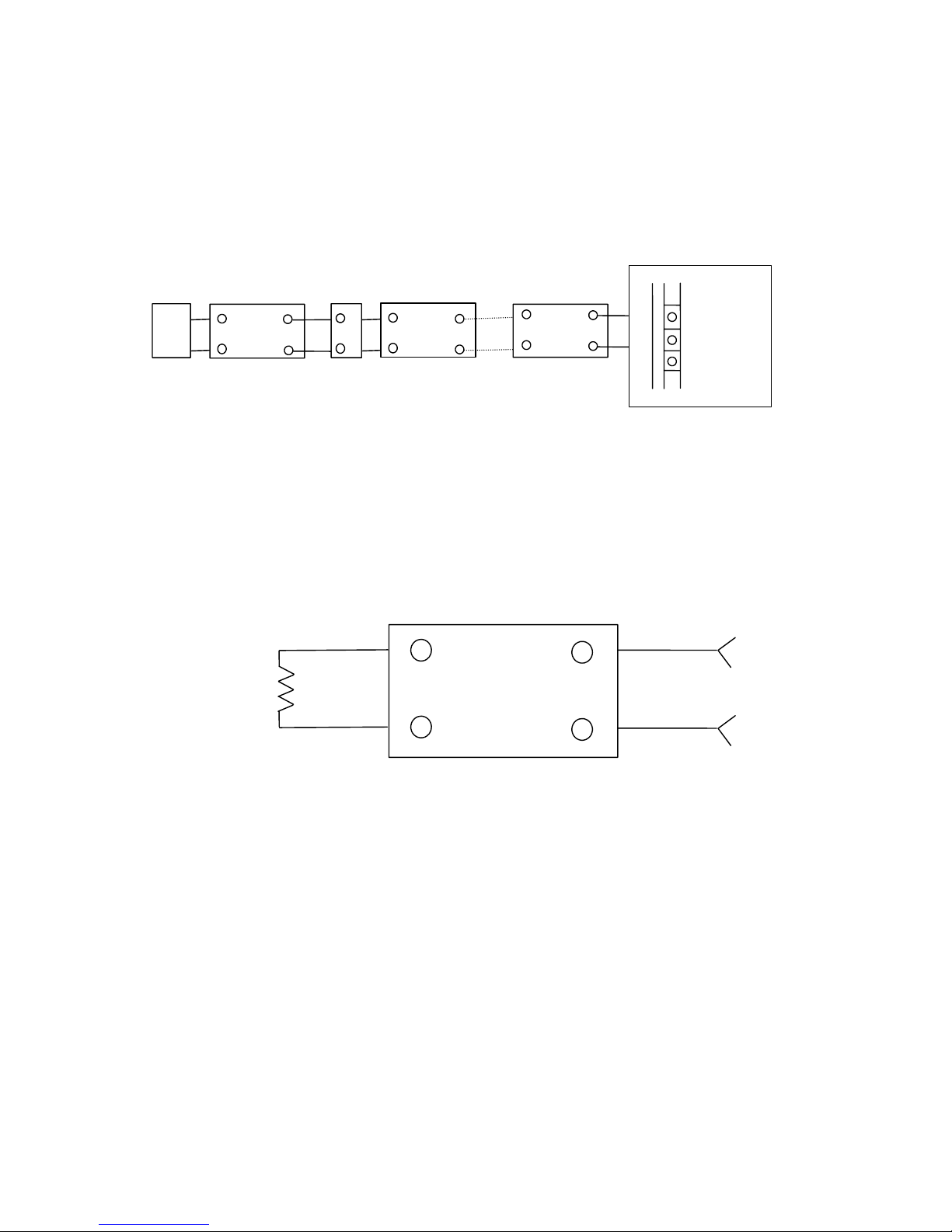
10) Figure 2.8 shows the correct way to wire an AZC with detectors and/or MCPs. The
MCPs and detectors may be in any order. The MCPs however must be the correct
type for 15V operation.
11) Figure 2.9 shows the correct way to wire the EOL resistor.
12) Figure 2.10 shows examples of INCORRECT AZC wiring.
13) When operating, circuit voltages at AZC terminals "+" and "-", should be as follows :
i. Between 23 and 24 VDC -> Fault (EOL open)
ii. Between 18 and 23 VDC -> Normal (EOL connected)
iii. Between 13 and 17 VDC -> MCP alarm (programmable)
iv. Less than 13 VDC -> Detector operated (programmable)
Interpretation of the 13-17 volt band and
0-13 volt band depends on the
programming of the circuit type as
described in Section 2.7.2.
Issue 3.04 24 March 2006 Page 2-13
Page 26
F08 Installation & Programming Manual Document No: LT0082
FIP Installation
+
-
AZC#
+
-
OUT
+
-
IN
+
-
OUT
+
-
IN
Detecto
r
+
-
MCP
+
-
OUT
+
-
IN
Detector
EOL
Figure 2.8
Example of Correct AZC Detector/MCP Wiring
+
-
OUT
+
-
IN
2k7 1% EOL
Resisto
r
Last Detector on
A
larm Zone Circuit
Figure 2.9
Correct EOL Wiring
Page 2-14 24 March 2006 Issue 3.04
Page 27

Document No: LT0082 F08 Installation & Programming Manual
FIP Installation
┌─┐ ┌──────┐ ┌──────┐ ┌──────┐ │ ├─┤
│E├───┼o+ +o┼──┼o+ +o┼── ─ ─ ─ ─ ─┼o+ +o┼───────────────┤O│ +
│O│ │OUT IN│ │OUT IN│ │OUT IN│ │ ├─┤AZC
│L├───┼o- -o┼──┼o- -o┼── ─ ─ ─ ─ ─┼o- -o┼───────────────┤O│ └─┘ └──────┘ └──────┘ └──────┘ │ ├─┤
┌─┐ ┌──────┐ ┌──────┐ ┌──────┐
│E├───┼o+ +o┼──┼o+ +o┼── ─ ─ ─ ─ ─┼o+ +o┼
│O│ │OUT IN│ │OUT IN│ │OUT IN│
│L├───┼o- -o┼──┼o- -o┼── ─ ─ ─ ─ ─┼o- -o┼
└─┘ └──────┘ └──────┘ └──────┘
┌─┐ ┌──────┐ ┌──────┐ ┌──────┐ │ ├─┤
│E├───┼o+ +o┼──┼o+ +o┼────────────┼o+ +o┼───────────────┤O│ +
│O│ │OUT IN│ │OUT IN│ │OUT IN│ │ ├─┤AZC
│L├───┼o- -o┼──┼o- -o┼────────────┼o- -o┼───────────────┤O│ └─┘ └──────┘ └──────┘ └──────┘ │ ├─┤
┌──────┐
│o+ +o┼
│OUT IN│
│o- -o┼
└──────┘
┌─┐ ┌──────┐ ┌──────┐ ┌──────┐ │ ├─┤
│E├───┼o+ +o┼──────────┼o+ +o┼────┼o+ +o┼───────────────┤O│ +
│O│ │OUT IN│ │OUT IN│ │OUT IN│ │ ├─┤AZC
│L├───┼o- -o┼──────────┼o- -o┼────┼o- -o┼───────────────┤O│ └─┘ └──────┘ └──────┘ └──────┘ │ ├─┤
┌─┐ ┌──────┐
│E├───┼o+ +o┼
│O│ │OUT IN│
│L├───┼o- -o┼
└─┘ └──────┘
Figure 2.10
Incorrect AZC Wiring Examples
Issue 3.04 24 March 2006 Page 2-15
Page 28

F08 Installation & Programming Manual Document No: LT0082
FIP Installation
2.7.2 INPUT TYPES
Each AZC can be programmed with one of ten different input types (refer Section 4.7).
These types are defined as follows and in Table 2.1.
Input Type 1 : Standard
Standard detector circuit without AVF. Both MCPs and detectors are allowed. Delay
into alarm is 2 seconds.
Input Type 2 : AVF/RAD
Standard detector circuit with AVF. MCPs are allowed and override AVF. AVF
sequence is: 2 seconds before first recognition, 5 second delay, 5 second reset, 2
second ignore, 2 second alarm recognition, 150 second acceptance period.
Input Type 3 : SAD
AS1668 SAD circuit (Supply Air Detector). 0-17V band is alarm with 2 seconds delay
into alarm and 60 seconds delay out of alarm. The detector must be non-latching and
the zone should be programmed as non-latching.
Input Type 4 : AVF/SAD
AS1668 AVF/SAD. 0-17V band is alarm with AVF (as for circuit type 2 AVF/RAD).
Delay out of alarm is 60 seconds. The detector must be non-latching and the zone
should be programmed as non-latching. 60 seconds of continuous non-alarm must be
present on the AZC input before the zone indicates non-alarm.
This input type can also be used with latching detectors that have a high alarm voltage
(up to 17V), when AVF is required (e.g. with IS isolating repeaters). Configure the
zone as latching. When the zone is reset the detector will be reset and the zone taken
out of alarm immediately, overriding the 60 second delay out of alarm.
Input Type 5 : Flowswitch
0-13V band is alarm with 20 second delay into alarm. 13-17V band is normal. The
detector is non-latching and the zone should be programmed as non-latching. 20
seconds of continuous alarm must be present on the AZC input before the zone
indicates alarm.
Input Type 6 : Standard/No MCP
Standard detector circuit without AVF. MCPs are not allowed and 13-17V band is
interpreted as fault to provide line leakage fault indication. The delay into alarm is 2
seconds. The delay into fault for 13-17V band is half a second.
Input Type 7 : AVF/RAD/No MCP
Standard detector circuit with AVF as for Type 2 AVF/RAD except that MCPs are not
allowed and 13-17V band is interpreted as fault to provide line leakage fault indication.
The delay into fault for 13-17V band is half a second.
Input Type 8 : Fast Supervision
13-17V band is alarm with half a second delay into alarm. 0-13V band is fault
providing both short circuit and open circuit fault detection. This is typically used for
sub-panel monitoring with sub-panel alarm relay in series with 15V zener diode. The
delay into fault for 0-13V band is half a second.
Page 2-16 24 March 2006 Issue 3.04
Page 29

Document No: LT0082 F08 Installation & Programming Manual
FIP Installation
INPUT TYPES (CONTINUED)
Input Type 9 : Loop Powered Circuit / Fast Alarm
0-13V band is alarm with half a second delay into alarm. 13-17V band is normal for
15V loop powered circuit.
Input Type 10 : Normally Closed Contact
13-17V band is alarm with 2 seconds delay into alarm. 0-13V band is interpreted as
normal.
Delay Out of Alarm
For a non-latching zone, the delay out of alarm for all circuit types other than type 3 (SAD)
and type 4 (AVF/SAD) is 120 millisconds.
Detector LED Current Boost
Input Type 1-7:
When the AZC input is currently in any alarm band, a 50 millisecond current boost will
be applied to the circuit once a second.
Input Type 8 (Fast Supervision), 9 (Loop Powered) and 10 (Normally Closed):
When the AZC input is currently in any alarm band and the zone is in alarm or latched
in alarm then a 50 millisecond current boost will be applied to the circuit once a
second.
INPUT TYPES
INPUT TYPE
VOLTAGE
1
INSTANT
2
AVF/RAD
3
SAD
4
AVF/SAD 5 FLOW SWITCH
24V Fault Fault Fault Fault Fault
17-23V Normal Normal Normal Normal Normal
13-17V 0-17 Volt treated
as the same
state.
Alarm after 2
seconds.
0-17 Volt
treated as the
same state.
0-17 Volt
treated as the
same state.
Normal
0-13V Alarm after 2
seconds.
AVF into alarm. Alarm after 2
seconds.
Delay out of
alarm is 60
seconds.
Alarm after
AVF.
Delay out of
alarm is 60
seconds.
20 Second
delay into
alarm.
No delay out of
alarm.
INPUT TYPE
VOLTAGE 6
LEAKY CCT
7
LEAKY CCT
& AVF
8
SUB-PANEL
S/C FAULT
9
FAST ALARM
10
NORMALLY
CLOSED
24V Fault Fault Fault Fault Fault
17-23V Normal Normal Normal Normal Normal
13-17V Fault
0.5 seconds
Fault
0.5 seconds
Alarm after
0.5 seconds.
Normal Alarm after 2
seconds.
0-13V Alarm after 2
seconds.
AVF into alarm. Fault after 0.5
seconds.
Alarm after 0.5
seconds.
Normal
AVF = 2 second alarm, 5 second delay (circuit still energised), 5 secon d reset, energise 2 second ignore,
start processing.
Table 2.1
F08 Input Types
Issue 3.04 24 March 2006 Page 2-17
Page 30

F08 Installation & Programming Manual Document No: LT0082
FIP Installation
2.8 BELL OUTPUT WIRING
2.8.1 GENERAL
At the bottom of J8 terminals "BELLS +" and "0V" are provided for connection to external bell
circuits. The Bell Output is a switched 24V DC output, derived from +VB through the Bell
fuse F1.
NOTES:
1) Connect ONLY 24 VDC devices.
2) Observe correct polarity for polarised devices, eg electronic sirens.
3) Maximum load current is 1.0 Amps as the bells are an inductive load. (Please note
total load constraints). For heavier loads use an interposing relay.
4) The "BELLS+" output is fused by fuse F1, labelled "BELLS", and is rated at 1.6 A.
5) The "BELLS" circuit is not supervised.
6) Figure 2.11 shows an example of bell wiring.
7) For optimum suppression install diodes across each BELL.
- Use diode type 1N4004 (400V 1A) or similar.
- Note polarity of diode. (Cathode to Bell Positive).
2.8.2 SUPERVISED BELL OUTPUT
A supervised bell output can be arranged with an optional 24V Bell Monitor Board (part
number PA0494) and a 24V GP Relay Board (part number PA0730). The Bell Monitor
Board supervises the bell wiring for open or short circuits.
On a fault, the Ext Def- output of the Bell Monitor goes “low” and turns off the relay on the
GP Relay Board, causing the EOLR to be disconnected from the F08’s detector circuit.
The AZC should be programmed as Input Type 1 (default option).
The Bell Monitor Board can support wiring of up to 3 separate branches (each with an EOL
resistor), and a load current of 1.0A (as limited by the F08 Bell Output). The end of line
resistor depends on the number of branches.
Number of Branches EOL
1
2
3
10k 5%
18k 5%
27k 5%
Note that a diode is required with any device that does not already contain a series diode.
Figure 2.12 shows the wiring arrangement for the Bell Monitor board.
The 10k pull-up resistor should be soldered between the Ext Def- tab and the left end of link
A3. After soldering, check that the solder joints on the bottom of link A3 are still good.
Page 2-18 24 March 2006 Issue 3.04
Page 31

Document No: LT0082 F08 Installation & Programming Manual
FIP Installation
/\/\/\/\/\/\/\/\/│
J8 │
──────── ┌┬─┐ │
A COM ││O│ │
L │├─┤ │
A NC ││O│ │
R │├─┤ │
M NO ││O│ │
──────── │├─┤ │
COM ││O│ │
│├─┤ │
A NC ││O│ │
N │├─┤ │
C NO ││O│ │
I │├─┤ │
L SUP ││O│ │
L │├─┤ │
A +VB ││O│ │
R │├─┤ │
Y +VNB ││O│ │
│├─┤ │
0V ││O│ │
──────── │├─┤ │ RED WIRE
BELLS+ ││O╞═══════════════════════════╦═══════╗
│├─┤ │ BLACK WIRE ║ ║
0V ││O╞════════╦═══════╗ DIODE ║ ║
──────── └┴─┘ │ ║ ║ _┌───╥┐_ ║ ║
▄▄ │ ║ ║│ └───╨┘ │║ ║╔══════════════╗
││ │ ║ ┌──╨┴────────┴╨──┐ ║║ REMEMBER ║
▀▀ │ ║ │ - + │ ║║ MAX LOAD ║
─────────────────┘ ║ │ BELL │ ║║ 1.0 A ║
║ │ │ ║╚══════════════╝
║ └────────────────┘ ║
║ ║
║ ║
╚═══════╗ ╔═══════╝
║ ║
║ DIODE ║
║ _┌───╥┐_ ║
║│ └───╨┘ │║
┌──╨┴────────┴╨──┐
│ - + │
│ BELL │
│ │
└────────────────┘
Figure 2.11
Bell Output Wiring
Issue 3.04 24 March 2006 Page 2-19
Page 32

F08 Installation & Programming Manual Document No: LT0082
FIP Installation
6+
6-
7+
7-
8+
8-
0V
BATT+
BATT-
EARTH
:
:
:
:
:
+VB
+VNB
0V
BELLS+
0V
PROGRAM
INPUT
TYPE 1
(
DEFAULT
)
+V
+V
7+
EVAC
0V
+VExt
0V
7+
EVAC-
EVAC+
PA0494 24V BELL
MONITOR BOARD
+
SIG
-
C
NC
NO
C
NC
PA0730 24V
RELAY BOARD
NO
+ +
* EOL
+ +
* EOL Value –
Refer to Bell
Monitor
Installation
Instructions
LT0190
F08 EOL
0V
BELLS+
+
A
3
*10k
Ext Def-
*Solder the 10k resistor from
the Ext Def- tab to the l.h.s.
of link A3
J3 J8
Cut Lk1
Figure 2.12
F08 Bell Output with PA0494 Bell Monitor Board
Page 2-20 24 March 2006 Issue 3.04
Page 33

Document No: LT0082 F08 Installation & Programming Manual
FIP Installation
2.8.3 CONNECTING T-GEN 50 TO F08
T-GEN 50 is a self contained AS2220 Alert and Evacuate tone generator and may be used
on the F08 as well as, or instead of, the standard bells output.
There are four ways to connect the T-GEN to the F08. For each the T-GEN must be
powered from the battery terminals through a 3A slow blow fuse and T-GEN’s DEF- output
wired into an AZC input to signal a fault with the wiring. This AZC must be programmed for
circuit type 8 (short circuit fault).
1) Connect T-GEN using the Bells Relay.
T-GEN requires a closed contact output to 0V to allow operation. The standard F08
Bells output is switched 24V so it needs to be modified.
1) Remove the “Bell Fuse” F1.
2) Solder a wire to the top Bell Fuse holder and connect it to 0V as per
Figure 2.13A.
3) Connect the T-GEN as per Figure 2.13A.
Issue 3.04 24 March 2006 Page 2-21
Page 34

F08 Installation & Programming Manual Document No: LT0082
FIP Installation
The T-GEN can then be connected as follows:
EARTH
BATT-
BATT+
0V
A
ZC-
A
ZC+
0V
BELLS+
0V
+VNB
+VB
:
:
:
:
:
F08
MAIN
BOARD
A
/I/F-
A
LM-
DEF-
SIG
PROGRAM
INPUT
TYPE 8
10k
5%
SOLDER WIRE
FROM TOP
HOLDER TO 0V
REMOVE BELLS
FUSE F1
+24V
+24V
0V
0V
Figure 2.13A
F08 using T-GEN on Bells Relay
T-GEN 50
F08
EOL
3A
SLOW
BLOW
FUSE
Page 2-22 24 March 2006 Issue 3.04
Page 35

Document No: LT0082 F08 Installation & Programming Manual
FIP Installation
2) Connect T-GEN using the Ancillary Relay.
If the Ancillary Relay is not being used, it may be used to control the T-GEN.
The Ancillary Relay must be programmed to operate on all the zones that require
tone signalling.
With the T-GEN connected in this fashion, pressing the silence key will not silence
the T-GEN, the only way T-GEN can be silenced is by isolating the Ancillary Relay.
Also, performing a Bells test will not activate T-GEN, the Ancillary Relay test will
need to be used instead.
Figure 2.13B
EARTH
BATT-
BATT+
0V
A
ZC-
A
ZC+
0V
BELLS+
0V
+VNB
+VB
SUP
NO
NC
COM
:
F08
MAIN
BOARD
A
/I/E-
A
LM-
DEF-
SIG
PROGRAM
INPUT
TYPE 8
10k
5%
+24V
+24V
0V
0V
T-GEN 50
F08
EOL
3A
SLOW
BLOW
FUSE
ANCILLARY
F08 using T-GEN on Ancillary Relay
Issue 3.04 24 March 2006 Page 2-23
Page 36

F08 Installation & Programming Manual Document No: LT0082
FIP Installation
3) Connect T-GEN using the Alarm Relay.
As the F08’s Brigade Interface has two Alarm contacts, the second set of contacts
may be used to activate T-GEN as shown in Figure 2.13C.
This method has some limitations. All zones that are required to operate the T-GEN
must be mapped to Master Alarm as well.
Pressing Silence will not silence T-GEN and this must be done through isolating all
zones in alarm.
There is no way of performing a Test on the T-GEN, except by putting a zone into
alarm.
Figure 2.13C
EARTH
BATT-
BATT+
0V
A
ZC-
A
ZC+
0V
BELLS+
0V
+VNB
+VB
SUP
NO
NC
COM
NO
F08
MAIN
BOARD
A
/I/E-
A
LM-
DEF-
SIG
PROGRAM
INPUT
TYPE 8
10k
5%
+24V
+24V
0V
0V
T-GEN 50
F08
EOL
3A
SLOW
BLOW
FUSE
NC
COM
ANCILLARY
ALARM
F08 using T-GEN on Alarm Relay
Page 2-24 24 March 2006 Issue 3.04
Page 37

Document No: LT0082 F08 Installation & Programming Manual
FIP Installation
4) Connect T-GEN using the Auxiliary Outputs.
The Ancillary outputs (Aux1 → Aux 8) may be used to operate T-GEN. The outputs
must be programmed as isolatable otherwise there will be no way of silencing T-GEN
apart from resetting the alarm condition. Also, Bells test will not operate T-GEN - a
zone alarm test can be used instead.
Wire the Auxiliary output of each zone that is to operate T-GEN together and connect
to T-GEN as per Figure 2.13D. These outputs are open collector, so they may be
wired in parallel. Figure 2.13D shows the wiring for zones 1, 2 and 4 operating TGEN
Figure 2.13D
F08 using T-GEN via Auxiliary Outputs
EARTH
BATT-
BATT+
0V
A
ZC-
A
ZC+
0V
+VNB
+VB
+VB
A
UX8
A
UX7
A
UX6
A
UX5
A
UX4
A
UX3
F08
MAIN
BOARD
A
/I/E-
A
LM-
DEF-
SIG
PROGRAM
INPUT
TYPE 8
10k
5%
+24V
+24V
0V
0V
T-GEN 50
F08
EOL
3A
SLOW
BLOW
FUSE
A
UX1
A
UX2
Issue 3.04 24 March 2006 Page 2-25
Page 38

F08 Installation & Programming Manual Document No: LT0082
FIP Installation
2.9 ANCILLARY RELAY OUTPUT WIRING
The "ANCILLARY" relay on connector block J8 provides voltage free changeover contacts.
Terminals available are:
(a) COM - Common
(b) NC - Normally Closed
(c) NO - Normally Open
(d) SUP - Input for supervision (Not voltage free).
NOTES:
1) Maximum allowable load is 18 ohms (1.5 A). Note that the total load current available
from the F08 is 1.5A.
2) Relay rating is 2 A @ 30 VDC resistive, 1 A inductive. Use interposing relay for
higher loads.
3) Only ELV is allowed into the cabinet.
4) The supervision input can be programmed to supervise the integrity of the circuit to
the controlled device. Allowable output load is 400 ohms to 4kohms. (A diode must
be added to loads < 400 ohms).
5) For supervised loads less than 400 ohms use a series diode, fitted at the load
(observe polarity and ensure diode rating is compatible with the load current).
6) For inductive loads use a suppression diode rated at 50 Volts or greater and a
current rating of:
- 0.5 A for loads greater than 100 ohms
- 1.0 A for loads greater than 30 ohms
- 1.5 A for loads greater than 20 ohms
7) For voltage free or non supervised loads, ensure that no connection is made to the
"SUP" input.
8) Figure 2.14 shows examples of wiring a device powered from the battery-backed
+VB.
9) The Ancillary relay can be isolated via the keypad, but Master Alarm, Fault, and
Isolate Relays cannot. They are however automatically isolated during System Test.
Page 2-26 24 March 2006 Issue 3.04
Page 39

Document No: LT0082 F08 Installation & Programming Manual
FIP Installation
/\/\/\/\/\/\/\/\/│
J8 │
──────── ┌┬─┐ │
A COM ││Q│ │
L │├─┤ │
A NC ││Q│ │
R │├─┤ │
M NO ││Q│ │
──────── │├─┤ │
A COM ││Q├───────────────────────────────────┐
N │├─┤ │ │
C NC ││Q├───────────┐ ├─────┐
I │├─┤ │ │ + │ │
L NO ││Q├───────┐ │ ┌──┴──┐ │
L │├─┤ │ │ │ INTERPOSING │ │ SUPPRESSION
A SUP ││Q├───────┼───┘ RELAY │ │ DIODE
R │├─┤ │ │ │ │
Y +VB ││Q├───────┘ └──┬──┘ │
│├─┤ │ - │ │
+VNB ││Q│ │ ├─────┘
│├─┤ │ │
0V ││Q├───────────────────────────────────┘
──────── │├─┤ │
\/\/\/\/\/\/\/\/\│
(A) Field Wiring for Interposing Device with a load Resistance greater than 400 OHMS
/\/\/\/\/\/\/\/\/│ SERIES DIODE
A COM ││Q├─────────────────── ─────────┐
N │├─┤ │ │
C NC ││Q├───────────┐ ├──────┐
I │├─┤ │ │ + │ │
L NO ││Q├───────┐ │ ┌──┴──┐ │
L │├─┤ │ │ │ INTERPOSING │ │ SUPPRESSION
A SUP ││Q├───────┼───┘ RELAY │ │ DIODE
R │├─┤ │ │ │ │
Y +VB ││Q├───────┘ └──┬──┘ │
│├─┤ │ - │ │
+VNB ││Q│ │ ├──────┘
│├─┤ │ │
0V ││Q├───────────────────────────────────┘
│├─┤ │
\/\/\/\/\/\/\/\/\│
(B) Field Wiring for Interposing Device with a load Resistance less than 400 OHMS
Figure 2.14
Examples of Supervised Ancillary Output
Issue 3.04 24 March 2006 Page 2-27
Page 40

F08 Installation & Programming Manual Document No: LT0082
FIP Installation
2.10 AUXILIARY OUTPUT WIRING
The "OPEN COLLECTOR" Auxiliary Outputs (AUX1 to AUX8) must only be connected to
external equipment via approved isolating devices such as relays or optoisolators mounted
within the panel.
An example of how to wire an auxiliary relay from the battery-backed supply +VB is shown in
Figure 2.15. In this example the relay turns on if zones 1 or 3 go into alarm.
NOTES:
(a) Use 24V devices, and allow for relay current in power requirement calculations.
(b) Use reverse E.M.F. suppression diode on relays.
(c) If a zone auxiliary output connects to more than one auxiliary relay, steering diodes
must be fitted.
(d) An auxiliary open collector output may or may not be isolated when the
corresponding zone is isolated depending on programming. Refer to Section 4.10.
(e) MAXIMUM current on each Auxiliary Output is 50 mA.
─────────────────┐
J6 │
┌┬─┐ │
AUX1 ││O╞════════════════════════╗
│├─┤ │ ║
AUX2 ││O│ │ ║
│├─┤ │ ║
AUX3 ││O╞════════════════════════╣
│├─┤ │ ║
AUX4 ││O│ │ ╔══════════╣ - ┌─┐
│├─┤ │ ║ ┌──╨──┐ ────────┤Q│ NC ┐ FIELD
AUX5 ││O│ │ ┌╨┐ │ │ ├─┤ │ WIRING
│├─┤ │ DIODE │ │ │RELAY│ ────┤Q│ COM │ TO
AUX6 ││O│ │ ╞═╡ │ │ ├─┤ │ RELAY
│├─┤ │ └╥┘ └──╥──┘ ────────┤Q│ NO ┘ CONTACTS
AUX7 ││O│ │ ║ ║ + └─┘
│├─┤ │ ╚══════════╣
AUX8 ││O│ │ ║
│├─┤ │ ║
+VB ││O╞════════════════════════╝
│├─┤ │
+VB ││O│ │
│├─┤ │
+VNB ││O│ │
│├─┤ │
+0V ││O│ │
└┴─┘ │
/\/\/\/\/\/\/\/\│
Figure 2.15
Example of Auxiliary Output Wiring
Page 2-28 24 March 2006 Issue 3.04
Page 41

Document No: LT0082 F08 Installation & Programming Manual
FIP Installation
2.11 DOOR HOLDER WIRING
The second "ALARM" (FIRE) relay on connector block J8 provides clean changeover
contacts suitable for Door Holder Power Supply connections. This operates on MASTER
ALARM and cannot be isolated manually via the F08 keypad.
NOTES:
1) The Master Alarm Relay will only operate if the zone in alarm is programmed to be
"mapped" to the Master Alarm Relay.
2) Use NON-BATTERY backed supply "+VNB" to power door holders.
3) "+VNB" rating is 1.5 A. ( Note total F08 load must be < 1.5A ).
4) Relay rating is 2 A @ 30 VDC resistive, 1A inductive.
5) Only ELV is allowed into the cabinet. Use an interposing relay located outside the
F08 cabinet if switching anything other than ELV.
6) For inductive loads, use a suppression diode rated at 50 Volts or greater and with a
current rating of:
- 0.5 A, for loads greater than 100 ohms
- 1.0 A, for loads greater than 30 ohms
- 1.5 A, for loads greater than 20 ohms
7) Figure 2.16 shows an example of Door Holder wiring. Note the normally closed
contact of the relay is used so that the door holders are de-energised on alarm.
/\/\/\/\/\/\/\/\/│
J8 │
──────── ┌┬─┐ │
A COM ││Q╞═══════════════════════╗
L │├─┤ │ ║
A NC ││Q╞═════════╗ ║
R │├─┤ │ ║ ║
M NO ││Q│ │ ║ ║
──────── │├─┤ │ ║ ║
A COM ││Q│ │ ║ ║
N │├─┤ │ ║ ╚═════════> +
C NC ││Q│ │ ║ TO DOOR HOLDERS
I │├─┤ │ ║ ╔═════════> L NO ││Q│ │ ║ ║
L │├─┤ │ ║ ║
A SUP ││Q│ │ ║ ║
R │├─┤ │ ║ ║
Y +VB ││Q│ │ ║ ║
│├─┤ │ ║ ║
+VNB ││Q╞═════════╝ ║
│├─┤ │ ║
0V ││Q╞═══════════════════════╝
──────── │├─┤ │
BELLS+ ││Q│ │
│├─┤ │
0V ││Q│ │
└┴─┘ │
▄▄ │
││ │
▀▀ │
─────────────────┘
Figure 2.16
Example of Door Holder Wiring
Issue 3.04 24 March 2006 Page 2-29
Page 42

F08 Installation & Programming Manual Document No: LT0082
FIP Installation
2.12 BRIGADE INTERFACE RELAYS
The F08 FIP provides space below the Mains Transformer and Mains Switch for the
installation of the Brigade Interfacing Devices.
A brigade interface bracket is available for fitting the following brigade interfacing units:
(a) Randata Deltec
(b) Mimimux Deltec
(c) Tyco Centaur ASE
(d) Line Isolating Unit; LIU001
(e) Torrens Transponder Unit
(f) Transponder Interface Adaptor; TIA001
The F08 provides four (4) sets of voltage free, changeover relay contacts at connector J7, as
shown in Figure 2.17.
The four relays are detailed below.
2.12.1 “STANDBY” RELAY
(a) Normally energised coil, (COM closed to NO).
(b) The Standby Relay de-energises on battery flat voltage, complete battery
power failure, watchdog timeout, or disconnection of the Display/Keyboard flat
ribbon cable. (ie. COM switches from NO to NC).
(c) THIS RELAY MUST BE USED T O SIGNAL TO THE BRIGADE ON ANY OF
THE ABOVE CONDITIONS, unless otherwise notified by the local Fire
Authority.
(c) If no "STANDBY" signal is required by the local Fire Authority, it is
recommended that a "LOCAL FAULT" alarm be activated by the "STANDBY"
relay.
** REMEMBER: WHEN THE "STANDBY" RELAY DE-ENERGISES, THE SYSTEM IS
INDICATING THAT IT IS NO LONGER AN OPERATIONAL FIRE
ALARM PANEL.
2.12.2 “FAULT” RELAY
(a) Normally de-energised.
(b) The Fault Relay will energise on any non-isolated fault condition on a zone
mapped to the "MASTER ALARM" or the supervised Ancillary Output. ( COM
switches from NC to NO). It will also energise on all enabled zones being
isolated.
Page 2-30 24 March 2006 Issue 3.04
Page 43

Document No: LT0082 F08 Installation & Programming Manual
FIP Installation
2.12.3 “ISOLATE” RELAY
(a) Normally de-energised.
(b) The Isolate Relay will energise on Isolation of any zone mapped to "MASTER
ALARM" or the supervised Ancillary Output. (ie. COM switches from NC to
NO).
2.12.4 “ALARM” RELAY
(a) Normally de-energised.
(b) The Alarm Relay will energise on an Alarm condition on any non-isolated
zone that is mapped to "MASTER ALARM". (i.e. COM switches from NC to
NO).
- Two sets of alarm contacts are provided, labelled "ALARM A" and
"ALARM B".
Normally "ALARM A" is used for brigade signalling and "ALARM B" is
used for Door Holders or other alarm functions.
NOTES:
(a) Some brigade interfaces require +24 VDC and 0 VDC, use "+VBF" and "0V"
terminals.
(b) Refer to instructions supplied with the Brigade interfacing units for connection
details.
Issue 3.04 24 March 2006 Page 2-31
Page 44

F08 Installation & Programming Manual Document No: LT0082
FIP Installation
/\/\/\/\/\/\/\/\/\/\/│
│├─┤ │
││Q│ +VB │ <─┐
│├─┤ │ │
││Q│ +VB │ <─┴── Use these terminals, if +24 VDC
│├─┤ │ Battery Backed voltage required
││Q│ +VNB │
│├─┤ │
││Q│ 0V │ <──── Use this terminal if 0 VDC is
└┴─┘ │ required
J7 │
┌┬─┐ ───── │
││Q│ COM │
│├─┤ │
STANDBY ││Q│ NC │ <──── "STANDBY" relay NORMALLY ENERGISED
│├─┤ │ (COM closed to NO)
││Q│ NO │
├┼─┤ ───── │
││Q│ COM │
│├─┤ │
FAULT ││Q│ NC │
│├─┤ │
││Q│ NO │
├┼─┤ ───── │
││Q│ COM │
│├─┤ │
ISOLATED ││Q│ NC │
│├─┤ │
││Q│ NO │
├┼─┤ ───── │
││Q│ COM │
ALARM │├─┤ │
(FIRE) ││Q│ NC │
│├─┤ │
││Q│ NO │
└┴─┘ │
/\/\/\/\/\/\/\/\/\/\/
\/\/\/\/\/\/\/\/\/\/\
││Q│ +VNB │
│├─┤ │
││Q│ 0V │
│├─┤ ───── │
││Q│ BELLS+│
│├─┤ │
││Q│ 0V │
└┴─┘ ───── │
▄▄ │
││ │
▀▀ │
─────────────────────┘
Page 2-32 24 March 2006 Issue 3.04
Page 45

Document No: LT0082 F08 Installation & Programming Manual
FIP Installation
Figure 2.17
Brigade Relay Termination
Issue 3.04 24 March 2006 Page 2-33
Page 46

F08 Installation & Programming Manual Document No: LT0082
FIP Installation
2.13 DISPLAY & ZONE LABELLING
2.13.1 ZONE NAMING LABEL
The F08 Zone Labelling can be simply done on a typewriter or word-processor.
Note: For a typewriter use a photocopy of the label supplied with the panel or
provided in Appendix A.3.
The type format is:
6 lines per inch.
30 characters at 10 CPI or 36 characters at 12 CPI
Two and a half (2.5) lines between each zone window.
To install the Zone Naming label, loosen the four left hand-side screws that hold the Display
Assembly onto the inner door. Insert the zone label behind the Keyboard mylar and adjust
such that the zone labelling is aligned correctly. Fasten the four screws.
2.13.2 DISPLAY BOARD REMOVAL OR INSTALLATION
The F08 Display Board is attached to the rear of the internal door by five M4 x 12mm screws
and flat washers.
To remove the display board simply unplug the display FRC from J1 on the Main Board, then
remove all 5 screws.
Reverse the process to install the display board.
2.13.3 MYLAR REPLACEMENT
To replace the Keyboard Mylar requires the front six Phillips-Head screws on the inside door
to be removed, leaving the center two to last.
The Display Board assembly has to be held whilst replacing the Mylar.
Replace the center two screws first and adjust the Mylar such that LEDs are aligned
correctly. Fasten the two center screws first, then all other screws.
Page 2-34 24 March 2006 Issue 3.04
Page 47

Document No: LT0082 F08 Installation & Programming Manual
FIP Installation
2.14 DOCUMENTATION
The following documentation MUST be included inside the F08 panel:
(a) F08 Operator's Manual
(b) A Maintenance Log-Book
(c) An "AS INSTALLED" fire detection system diagram and/or summary describing the
installed layout of the F08 fire detection system.
Issue 3.04 24 March 2006 Page 2-35
Page 48

Page 49

Document No: LT0082 F08 Installation & Programming Manual
Placing into Operation
3. PLACING INTO OPERATION
Issue 3.04 24 March 2006 Page 3-1
Page 50

F08 Installation & Programming Manual Document No: LT0082
Placing into Operation
3.1 GENERAL
Before undertaking any placing into operation activities, inspect the unit interior visually.
Check that all panel equipment is securely mounted and that all cables are connected at the
appropriate points (see Figure 3.1).
3.2 MAINS ISOLATE SWITCH
To switch the F08 FIP ON or OFF, open the front protective door. The "MAINS ISOLATE
SWITCH" is located at the bottom of the cabinet, to the right of the mains transformer. This
switch controls the mains power supply to the panel, including the battery charger.
The normal position of this switch is ON and should only be turned OFF (ie MAINS
ISOLATED), when testing that the FIP will run on batteries, or when servicing the unit.
NOTE: The Battery is not disconnected by the "MAINS ISOLATE SWITCH".
Page 3-2 24 March 2006 Issue 3.04
Page 51

Document No: LT0082 F08 Installation & Programming Manual
Placing into Operation
Figure 3.1
F08 Internal View
Issue 3.04 24 March 2006 Page 3-3
Page 52

F08 Installation & Programming Manual Document No: LT0082
Placing into Operation
3.3 POWER UP
To place a correctly installed and programmed F08 FIP into operation perform the following
steps:
STEP 1 : Ensure that the Mains Isolate Switch is OFF and that 240VAC is
available to the panel from the mains distribution switchboard.
STEP 2 : Disconnect or physically isolate any outputs that must not be activated
as a result of an alarm or fault during commissioning. Eg Fire Brigade,
Alarm Bells or Suppression System.
STEP 3 : Turn the Mains Isolate Switch ON.
STEP 4 : Check that the green "MAINS ON" LED indicator is illuminated and all
other LED indicators are OFF.
STEP 5 : Perform a System Test.
(a) With the FIP in GLOBAL mode (all "SEL" LED indicators OFF)
Press the key once.
(b) The amber "ISO" LED indicators for Ancillary Relay, Master Alarm and Alarm
Bells will illuminate.
TEST
(c) After 5 seconds all LED indicators will illuminate and the internal sounder will
produce a steady tone for a period of 2 seconds.
(d) A fault test will be carried out on each enabled and non-isolated zone,
stepping through zones by illuminating the "SEL" and "FLT" LED indicators.
(e) An alarm test will be carried out on each enabled and non-isolated zone,
stepping through zones by illuminating "SEL" and "ALM" LED indicators.
(f) All indicators turn off. (Except MAINS ON)
(g) If a zone fault or alarm occurs during the test or the test fails, then check the
AZC connections.
STEP 6 : Install and connect the batteries.
Page 3-4 24 March 2006 Issue 3.04
Page 53

Document No: LT0082 F08 Installation & Programming Manual
Placing into Operation
POWER UP (CONTINUED)
STEP 7 : Perform a Battery Test.
(a) Select Battery/Charger ( By pressing SELECT until the Battery/Charger "SEL"
indicator is illuminated).
(b) Press the key once.
- The Battery/Charger "SEL" indicator will flash to indicate a battery test
is in progress.
TEST
- The test will take 1 minute to complete.
(c) If the Battery test fails the amber "FLT" LED indicator will flash;
i. Check battery connections;
ii. If the battery is flat, leave on charge for 24 hours and retest.
iii. Check Battery Low Monitoring circuit for correct operation.
STEP 8 : Perform an MCP test.
(a) Insert the plastic MCP test key into the MCP for a period of 2 to 3 seconds.
(b) The zone that the MCP is wired to should indicate an alarm by flashing its
"ALARM" LED and any programmed outputs should operate.
(c) Press the key once to clear the ALARM.
(d) Disconnect a wire at the MCP.
RESET
(e) The zone that the MCP is wired to should indicate a fault by a steady "FLT"
LED.
(f) Re-connect the wire to the MCP.
(g) Press the SELECT key until the MCP zone is selected.
Press the key once to clear the FAULT.
RESET
Issue 3.04 24 March 2006 Page 3-5
Page 54

F08 Installation & Programming Manual Document No: LT0082
Placing into Operation
3.4 COMMISSIONING CHECKLIST
The commissioning of an F08 FIP is the most important phase of any contract.
If any problems are not corrected in this stage, experience shows that even the simplest of
mistakes can cause major problems over a long period of time.
The following procedure should be regarded as the minimum requirements for a
commissioning check.
Please complete this checklist carefully. Some major points to be noted are:
1. Ensure that the F08 FIP is correctly programmed to meet statutory requirements and
the Customer's specifications.
2. Ensure the INSTALLATION meets the standards defined by AS1670.1 and any other
local standards.
3. Ensure that the "AS INSTALLED" drawing represents the TRUE site installation,
complete with;
(a) Detector location and types.
(b) F08 FIP Programmed Configuration.
4. Ensure that a copy of the "AS INSTALLED" drawing is included inside the panel for
maintenance purposes.
5. Ensure that a copy of the "F08 OPERATOR'S MANUAL" is included inside the panel
and the system detail pages are completed.
6. Ensure that interface devices are connected to the "AUXILIARY OUTPUTS" if these
outputs are used externally.
7. Ensure that only APPROVED brigade interfacing devices are connected to the
brigade relays; "STANDBY", "FAULT", "ISOLATE", and "ALARM" (FIRE).
- Approved interfaces include:
(a) Randata Deltec
(b) Minimux Deltec
(c) Torrens Transponder
via Transponder Interface Adapter - TIA001
(d) Line Isolating Unit - LIU001
(e) MFB - Alarm Interface Unit.
(f) Tyco Fire Monitoring - Centaur.
8. Ensure that all ENABLED ZONES, ANCILLARY RELAY and ALARM BELLS can be
isolated.
9. Ensure batteries are charged and that a battery test passes. Turn off the mains
switch and check the system operates off the batteries.
Page 3-6 24 March 2006 Issue 3.04
Page 55

Document No: LT0082 F08 Installation & Programming Manual
Placing into Operation
COMMISSIONING CHECKLIST (CONTINUED)
10. Ensure System and Zone Tests perform satisfactorily.
11. Verify the programming, wiring and operation of the system.
Ie Check for each zone:
a) Alarm and fault conditions can be generated.
b) The alarm delay is as the input type. Ie Normal, AVF, 1668 or Flow Switch.
c) The zone is enabled and latching or non-latching as required.
d) The appropriate outputs (Ancillary Relay, Auxiliary, Brigade and bells) operate
as programmed or wired.
e) The Ancillary Relay supervision detects open and short circuit faults, if it is
enabled.
Issue 3.04 24 March 2006 Page 3-7
Page 56

F08 Installation & Programming Manual Document No: LT0082
Placing into Operation
THIS PAGE INTENTIONALLY LEFT BLANK
Page 3-8 24 March 2006 Issue 3.04
Page 57

Document: LT0082 VIGILANT F08 Installation & Programming Manual
Programming
4. PROGRAMMING
Issue 3.04 24 March 2006 Page 4-1
Page 58

VIGILANT F08 Installation & Programming Manual Document: LT0082
Programming
4.1 PROGRAMMING FEATURES
The F08 FIP provides a "PROGRAMMING MODE" so that the installer can configure the
panel to meet specified input and output requirements.
Programming should only be carried out by a suitably qualified FIRE-PROTECTION
technician or engineer.
If the F08 FIP was pre-programmed prior to delivery, it may NOT NEED TO BE RE-
PROGRAMMED in the field.
The F08 "PROGRAMMING MODE" provides four (4) programming functions with
the programming keys and indications summarised in Tables 4.1 and 4.2.
FUNCTION 1; ZONE OUTPUT MAPPING
This programming function allows the programmer to select which of the zone inputs will
operate each of the following outputs:
i. Ancillary Relay
ii. Master Alarm
iii. Alarm Bells.
FUNCTION 2; ZONE LATCHING / NON-LATCHING
This programming function enables the programmer to select zone inputs as alarm state
latching or non latching and fault state latching or non-latching.
FUNCTION 3; ZONE INPUT TYPE
This programming function enables the programmer to select for each zone, one of the
following input types. (Refer Section 2.7.2 for a full description):
i. 2 second transient suppression delay to alarm (default). Both detectors and 15V
MCP allowed on circuit.
ii. AVF/RAD 16 second delay to alarm for detectors, 2 second delay to alarm for 15V
MCP.
iii. AS1668 SAD. Delay into alarm 2 seconds. Delay out of alarm 60 seconds.
Detector is non-latching and zone should be programmed as non-latching.
iv. AS1668 AVF/SAD. 16 second AVF delay into alarm. Delay out of alarm 60
seconds. Detector is non-latching and zone should be programmed as non-latching.
v. Flowswitch. 20 second delay into alarm. No delay out.
vi. 2 second delay to alarm. Detectors only. MCP not allowed. 13-17V band indicates
fault. This circuit type is used to provide line leakage fault indication.
vii. AVF/RAD 16 second delay into alarm. Detectors only - MCP not allowed. 13-17V
band indicates fault. This circuit type is used to provide line leakage fault indication.
viii. Fast alarm - 0.5 seconds delay into alarm for supervisory contact with 15V zener
diode. This is typically used for sub-panel monitoring. 0-13V band indicates fault.
ix. Fast alarm - 500 milliseconds delay into alarm for 0-13V band. 13-17V band is
normal for 15V loop powered circuit.
x. Delay into alarm is 2 seconds for 13-17V band. 0-13V band is normal for normally
closed (S/C) circuit.
Page 4-2 24 March 2006 Issue 3.04
Page 59

Document: LT0082 VIGILANT F08 Installation & Programming Manual
Programming
PROGRAMMING FEATURES (CONTINUED)
FUNCTION 4; ZONE & ANCILLARY RELAY SUPERVISION - ENABLED / DISABLED;
AUXILIARY ZONE OUTPUT OPERATION MODE
This programming function enables the programmer to select which zone inputs are enabled
and also select whether or not the Ancillary Relay Output is Supervised. Disabled zones do
not require EOL units and are inhibited from any zone or system tests.
This function is also used to select whether or not isolating a zone forces the auxiliary zone
output to be off - this is a single global parameter which applies to all eight zones.
┌─────────────────────────┬──────────┬─────────────────────────────┐
│ FUNCTION │PRESS KEY │ COMMENTS │
╞═════════════════════════╧══════════╧═════════════════════════════╡
│┌────────────────────────┬──────────┬────────────────────────────┐│
││ ENTER PROGRAMMING │ PROGRAM │Located on Main Board ││
││ MODE │ │PRESS & HOLD FOR 4 BEEPS ││
││ │ │-Zone Output Mapping ││
││ │ │entered for "ANCIL RELAY" ││
│└────────────────────────┴──────────┴────────────────────────────┘│
│ │
│┌────────────────────────┬──────────┬────────────────────────────┐│
││ EXIT PROGRAMMING MODE │ PROGRAM │Sounder on Continuously ││
││ │ │-Select one EXIT FUNCTION: ││
│├────────────────────────┼──────────┼────────────────────────────┤│
││ 1. EXIT WITHOUT │ TEST │Parameters NOT changed ││
││ SAVING CHANGES │ │-EXITS TO NORMAL OPERATION ││
│├────────────────────────┼──────────┼────────────────────────────┤│
││ 2. EXIT AND SAVE │ SELECT │Parameters SAVED in EEPROM ││
││ CHANGES │ │with any changes made. ││
││ │ │-EXITS TO NORMAL OPERATION ││
│├────────────────────────┼──────────┼────────────────────────────┤│
││ 3. RESET TO DEFAULT │ RESET │Parameters forced to default││
││ PARAMETERS │ │state. ││
││ │ │-REMAINS IN PROGRAMMING MODE││
│└────────────────────────┴──────────┴────────────────────────────┘│
└──────────────────────────────────────────────────────────────────┘
Table 4.1
Programming Key Summary - Entering/Exiting Programming Mode
Issue 3.04 24 March 2006 Page 4-3
Page 60

VIGILANT F08 Installation & Programming Manual Document: LT0082
Programming
FUNCTION PRESS KEY INDICATED BY
1. Enter into Zone Output
Mapping
TEST Ancil Relay “SEL” LED Flashing
Output “ISO” LEDs Flashing
Select Output for Mapping TEST Selected Output “SEL” LED Flashing
Select Zones SELECT Selected Zone “SEL” LED ON
Output “SEL” LED Flashing
Zone Mapped to Selected
Output
TEST “ALM” LED Steady = MAPPED
(TOGGLE) “ALM” LED Off = NOT MAPPED
2. Enter into Zone Latching/
Non-Latching Programming
RESET Selected Zone “SEL” LED ON
Zone fault state non-latching indicated
by zone fault LED ON. Zone alarm
state non-latching indicated by zone
alarm LED ON.
Select Zone SELECT Selected Zone “SEL” LED ON
Toggle as Latching or Non-
Latching
RESET Fault/Alarm LED ON = Non-latching,
LED OFF = Latching.
(CYCLES)
3. Enter into Zone Input Type
Programming
SILENCE Selected Zone “SEL” LED ON
“FLT”, “ALM”, & “ISO” LEDs ON for
Zone 1 - 8, 8 + 1, 8 + 2
Select Zone SELECT Selected Zone “SEL” LED ON
“FLT”, “ALM”, & “ISO” LEDs ON for:
Select Zone Delay SILENCE
ZONE 1 = Default 2s transient
ZONE 2 = AVF/RAD
ZONE 3 = 1668 SAD
ZONE 4 = 1668 AVF/SAD
ZONE 5 = FSI 20 second
ZONE 6 = 2 secs alarm. No MCP
ZONE 7 = AVF/RAD. No MCP
ZONE 8 = Fast alarm with supervision
ZONE 8+1= Fast alarm, 15V loop pwr
ZONE 8+2=2 Secs alarm, S/C = nml
4. Enter into Enabling or
Disabling Zones, and
Ancillary Relay Supervision
ISOLATE Selected Zone “SEL” LED ON
Disabled Zones indicated by zone
“ISO” LED ON
ANCIL RELAY Supervision
Disabled if “ISO” LED ON
Zone auxiliary outputs are “isolatable” if
Master Alarm “ISO” LED ON.
Select Zone SELECT Selected Zone “SEL” LED ON
ISOLATE “ISO” LED ON = Zone Disabled
Select Zone as Enabled or
Disabled
(TOGGLE) “ISO” LED OFF = Zone Enabled
OR
“ISO” LED ON = SUP. Disabled
Select Ancil Relay
Supervision as Enabled or
Disabled
“ISO” LED OFF = SUP. Enabled
OR
Master Alarm “ISO” LED ON =
isolatable, OFF = output ignores zone
isolate
Select Zone Auxiliary output
isolatable or not.
Table 4.2 - Programming Key Summary - Programming Mode Enabled
Page 4-4 24 March 2006 Issue 3.04
Page 61

Document: LT0082 VIGILANT F08 Installation & Programming Manual
Programming
4.2 ENTERING PROGRAMMING MODE
Located at the top left hand side of the main board is a push-button labelled "PROGRAM".
MAIN BOARD - Top Left-Hand Side
┌─────────────────────────────────────
│ ┌─┐ ┌────────────┐
│ ├─┤ │OOOOOOO OOOO│
Display Connector ────>│ │ └────────────┘
│ │ │
│ │ │┌───┐
│ ├─┤│ O │ PROGRAM
│ └─┘└───┘
Figure 4.1
Location of "PROGRAM" pushbutton
TO ENTER "PROGRAMMING MODE":
┌───┐ Press and hold the "PROGRAM" pushbutton key for four (4) beeps
│ O │ of the sounder.
└───┘
- All output amber "ISO" LEDs start flashing.
- The "ZONE OUTPUT MAPPING" programming function is automatically
selected upon entry into the "PROGRAMMING MODE".
- The green "SEL" indicator of ANCILLARY RELAY starts flashing.
- Zones that are mapped to ANCILLARY RELAY are indicated by their "ALM"
zone LEDs being ON.
* * PLEASE NOTE * *
"PROGRAMMING MODE" cannot be activated if:
1) A system test is currently being performed;
2) A zone test is being performed;
3) Any zone has an unsilenced and non-isolated alarm or fault condition;
4) A battery test is currently being performed; or
5) Any key is depressed.
Issue 3.04 24 March 2006 Page 4-5
Page 62

VIGILANT F08 Installation & Programming Manual Document: LT0082
Programming
4.3 EXITING PROGRAMMING MODE
4.3.1 WITHOUT SAVING CHANGES
This sequence exits "PROGRAMMING MODE" without saving any changed parameters.
I.E. the system returns to normal operation with the same parameters that existed prior to
entering the programming mode.
┌───┐ Press the "PROGRAM" pushbutton key once to exit
│ O │ "PROGRAMMING MODE".
└───┘
- A steady tone sound will be heard.
Press the "TEST" key once within 4 minutes of pressing the
"PROGRAM" pushbutton.
TEST
- "PROGRAMMING MODE" is terminated.
- The sounder will turn off.
- Panel indicators will return to the state prior to entering
"PROGRAMMING MODE".
- SELECT will be in global mode.
- All changes made during "PROGRAMMING MODE" will be
lost.
4.3.2 SAVING CHANGES
This sequence exits "PROGRAMMING MODE", saves all changed parameters in EEPROM
and returns the system to normal operation.
┌───┐ Press the "PROGRAM" pushbutton key once to exit
│ O │ "PROGRAMMING MODE".
└───┘
- A steady tone sound will be heard.
Press the "SELECT" key once within 4 minutes of pressing the
"PROGRAM" pushbutton.
SELECT
- "PROGRAMMING MODE" is terminated.
- The sounder will turn off.
- Panel indicators will return to the state prior to entering
"PROGRAMMING MODE".
- SELECT will be in global mode.
- Any DISABLED ZONE which was programmed to be enabled
will now be isolated.
- All programmed changes will now be in effect.
Page 4-6 24 March 2006 Issue 3.04
Page 63

Document: LT0082 VIGILANT F08 Installation & Programming Manual
Programming
4.4 RESET TO DEFAULT PARAMETERS
This sequence returns all programmable system parameters to the following default settings,
but leaves the user in "PROGRAMMING MODE" still.
(a) All zones enabled.
(b) All zones latching for both alarms and faults.
(c) All zones have an Input Type of 1 - default 2 second delay.
(d) All zones mapped to all outputs.
(e) Ancillary Relay is NOT supervised.
(f) Zone auxiliary outputs are isolatable.
┌───┐ Press the "PROGRAM" pushbutton key once
│ O │ to exit "PROGRAMMING MODE".
└───┘
- A steady tone sound will be heard.
Press the "RESET" key once within 4 minutes of pressing the
PROGRAM" pushbutton.
RESET
- The sounder will beep 4 times.
- All Output amber "ISO" LEDs will be flashing.
- All zone "SEL" LEDs will be flashing.
- All zone "SEL" LEDs stop flashing and the "OUTPUT
MAPPING" programming function is automatically selected.
- The green "SEL" indicator of the ANCILLARY RELAY starts
flashing.
- All zone "ALM" LEDs are turned ON.
- The Fault relay will energise as all zones are isolated as a
result of the parameter reset function.
Issue 3.04 24 March 2006 Page 4-7
Page 64

VIGILANT F08 Installation & Programming Manual Document: LT0082
Programming
4.5 PROGRAMME ZONE TO OUTPUT MAPPING
4.5.1 FUNCTION
Selects which zone inputs will activate the following outputs:
a) "ANCILLARY RELAY"
b) "MASTER ALARM"
c) "ALARM BELLS".
When a zone input is mapped to an output, that output will be turned on if an alarm is
detected on the zone and it is not isolated. If the zone is mapped to the MASTER ALARM
output, then a fault or isolation on the zone will operate the respective brigade relay output.
4.5.2 ENTERING THIS MODE
This function is automatically selected upon entry to "PROGRAMMING MODE" or after
performing a "PROGRAMMING RESET" function. If in any other programming function,
perform the following steps to enter this mode.
Press the "TEST" key once.
- The green "SEL" LED flashes on "ANCILLARY RELAY" as the
first output selected.
TEST
- All zones mapped to the "ANCILLARY RELAY" will be
indicated by the zone "ALM" LED being ON.
- The amber "ISO" LEDs on ANCILLARY RELAY, MASTER
ALARM and ALARM BELLS will be flashing.
Press the "TEST" key to rotate around the three outputs until the
required output is selected, indicated by its "SEL" LED flashing.
┌────────────┐ ┌────────────┐ ┌────────────┐
TEST
┌──>─┤ANCIL. RELAY├──>─┤MASTER ALARM├──>─┤ALARM BELLS ├──>─┐
│ └────────────┘ └────────────┘ └────────────┘ │
│ │
└───────────────────────────────<──────────────────────────┘
- Zones mapped to the selected output will be indicated by their
zone "ALM" LED being ON.
Page 4-8 24 March 2006 Issue 3.04
Page 65

Document: LT0082 VIGILANT F08 Installation & Programming Manual
Programming
4.5.3 MAPPING ZONES TO SELECTED OUTPUT
Press the "SELECT" key once.
- Zone 1 "SEL" LED will turn ON.
- Selected Output "SEL" LED continues to flash.
SELECT
Press the "TEST" key to toggle the mapping state.
- "ALM" LED ON = Zone mapped to output.
- "ALM" LED OFF = Zone not mapped to output.
Press "SELECT" key to select zones 2 to 8.
- Zone "SEL" LED illuminated indicates zone selected.
** After pressing the "SELECT" key on zone 8, a BLANK POSITION will be selected,
where no zone "SEL" LEDs are turned ON.
SELECT
TEST
- In this position the "TEST" key may be pressed to select another output.
Issue 3.04 24 March 2006 Page 4-9
Page 66

VIGILANT F08 Installation & Programming Manual Document: LT0082
Programming
4.5.4 EXAMPLE 1
Enter "PROGRAMMING MODE", then reset the parameters to default as shown below:
┌───┐ ┌───┐ ╓▄▄▄▄▄▄▄▄▄▄┐
│ O │ ────────────────────────> │ O │ ──> ║ RESET │
└───┘ └───┘ ╚══════════╛
Hold "PROGRAM" for 4 Beeps Press "PROGRAM" Again" then Press
to enter Programming Mode "RESET" key once to reset parameters.
"PROGRAMMING MODE" will automatically be in ZONE OUTPUT MAPPING function.
Follow the following keypad steps to select the following mapping:
(a) ANCILLARY RELAY is operated by all zones except 2 and 6.
(b) MASTER ALARM is operated by all zones except 4 and 6.
(c) ALARM BELLS is operated by all zones except 6.
As the default setting is all zones mapped to all outputs it is only necessary to "de-map"
those zones not required for each output.
(a) Re-map ANCILLARY RELAY
│
│ Select Select DE-MAP Select
│ Zone 1 Zone 2 Zone 2 Zone 3
│ ╓──────────┐ ╓──────────┐ ╓──────────┐ ╓──────────┐
└───>║ SELECT │──>║ SELECT │──>║ TEST │──>║ SELECT │ ──>─┐
╚══════════╛ ╚══════════╛ ╚══════════╛ ╚══════════╛ │
"ALM" LED OFF │
│
┌─────────────────────────────────────<────────────────────────────┘
│
│ Select Select Select DE-MAP
│ Zone 4 Zone 5 Zone 6 Zone 6
│ ╓──────────┐ ╓──────────┐ ╓──────────┐ ╓──────────┐
└───>║ SELECT │──>║ SELECT │──>║ SELECT │──>║ TEST │───>─┐
╚══════════╛ ╚══════════╛ ╚══════════╛ ╚══════════╛ │
"ALM" LED OFF │
│
┌─────────────────────────────────────<────────────────────────────┘
│
│ Select Select Select
│ Zone 7 Zone 8 Global
│ ╓──────────┐ ╓──────────┐ ╓──────────┐ ┌───────────────┐
└────>║ SELECT │──>║ SELECT │──>║ SELECT │──>│ Continued (b) │
╚══════════╛ ╚══════════╛ ╚══════════╛ └───────────────┘
Page 4-10 24 March 2006 Issue 3.04
Page 67

Document: LT0082 VIGILANT F08 Installation & Programming Manual
Programming
EXAMPLE 1 (CONTINUED)
┌────────────────────────┐
│(b) Re-map MASTER ALARM │
└─┬──────────────────────┘
│ Select Select Select Select
│ Master Alarm Zone 1 Zone 2 Zone 3
│ ╓──────────┐ ╓──────────┐ ╓──────────┐ ╓──────────┐
└──>║ TEST │──>║ SELECT │──>║ SELECT │──>║ SELECT │──>─┐
╚══════════╛ ╚══════════╛ ╚══════════╛ ╚══════════╛ │
"SEL" LED FLASHING │
│
┌─────────────────────────────────────<────────────────────────────┘
│
│ Select DE-MAP Select Select
│ Zone 4 Zone 4 Zone 5 Zone 6
│ ╓──────────┐ ╓──────────┐ ╓──────────┐ ╓──────────┐
└────>║ SELECT │──>║ TEST │──>║ SELECT │──>║ SELECT │──>─┐
╚══════════╛ ╚══════════╛ ╚══════════╛ ╚══════════╛ │
"ALM" LED OFF │
│
┌─────────────────────────────────────<────────────────────────────┘
│
│ DE-MAP Select Select Select
│ Zone 6 Zone 7 Zone 8 Global
│ ╓──────────┐ ╓──────────┐ ╓──────────┐ ╓──────────┐
└────>║ TEST │──>║ SELECT │──>║ SELECT │──>║ SELECT │──>─┐
╚══════════╛ ╚══════════╛ ╚══════════╛ ╚══════════╛ │
"ALM" LED OFF │
│
┌───────────────────────┐ │
│(c) Re-Map ALARM BELLS ├──────────────────────────────────────────┘
└─┬─────────────────────┘
│ Select Select Select Select
│ Alarm Bells Zone 1 Zone 2 Zone 3
│ ╓──────────┐ ╓──────────┐ ╓──────────┐ ╓──────────┐
└──>║ TEST │──>║ SELECT │──>║ SELECT │──>║ SELECT │──>─┐
╚══════════╛ ╚══════════╛ ╚══════════╛ ╚══════════╛ │
"SEL" LED FLASHING │
│
┌─────────────────────────────────────<────────────────────────────┘
│
│ Select Select Select RE-MAP
│ Zone 4 Zone 5 Zone 6 Zone 6
│ ╓──────────┐ ╓──────────┐ ╓──────────┐ ╓──────────┐
└────>║ SELECT │──>║ SELECT │──>║ SELECT │──>║ TEST │──>─┐
╚══════════╛ ╚══════════╛ ╚══════════╛ ╚══════════╛ │
"ALM" LED OFF │
┌─────────────────────┐ │
│ Continued Example 2 │ <─────────┘
└─────────────────────┘
Issue 3.04 24 March 2006 Page 4-11
Page 68

VIGILANT F08 Installation & Programming Manual Document: LT0082
Programming
4.6 PROGRAMMING ZONES AS LATCHING OR NON-LATCHING
4.6.1 FUNCTION
This function selects which zone inputs will be latching or non-latching for ALARM and
latching or non-latching for FAULT. I.e. if the alarm state is programmed as latching, it
means that the zone will remain in alarm after the alarm condition has been removed from
the circuit input, and must be reset by an operator. If the fault state is programmed as
latching it means that the zone will remain in fault after the fault condition has been removed
from the circuit input, and must be reset by an operator.
* DEFAULT: ALARM AND FAULT BOTH LATCHING
4.6.2 OPERATING STEPS
Press the "RESET" key once.
- All zones for which the alarm state is non-latching will have
their ALARM LED on and all zones for which the fault state is
non-latching will have their FAULT LED on.
RESET
- The green "SEL" LED will be on for the last zone selected or
otherwise, zone 1.
- Amber "ISO" LEDs on ANCILLARY RELAY, MASTER ALARM
and ALARM BELLS will be flashing.
Press the "SELECT" key until the green "SEL" LED indicator is at the
required zone.
Press the "RESET" key to cycle the zone Latching/Non-latching
states through the four states as follows:
Alarm and Fault both latching : Alarm and Fault LEDs OFF
Alarm non-latching, Fault latching : Alarm LED ON Fault LED OFF
Alarm latching, Fault non-latching : Alarm LED OFF, Fault LED ON
Alarm non-latching, Fault non-latching : Alarm LED ON, Fault LED ON
RESET
SELECT
* Press the "SELECT" key to move to other zones or press "TEST", "SILENCE", or
"ISOLATE" keys to perform other programming functions.
Page 4-12 24 March 2006 Issue 3.04
Page 69

Document: LT0082 VIGILANT F08 Installation & Programming Manual
Programming
4.6.3 EXAMPLE 2
Continuing from example 1, perform the following keypad steps to select:
Zone 6 - alarm latch, fault non-latch
Zone 2 - alarm non-latch, fault non-latch
Zone 5 - alarm non-latch, fault latch
Continued from Example 1
Zone 6 currently selected
RESET
Enter Latching/
Non-latching
Function
RESET
Zone 6
Alarm Latch
Fault Non-Latch
Alarm LED Off
Fault LED On
RESET
Zone 6
Alarm LED On
Fault LED Off
SELECT
Select Zone 8
Select Zone 7
SELECT
SELECT
Select Zone 1
RESET
SELECT
Select Zone 2
RESET
SELECT
Select Zone 3
RESET
Zone 2
Alarm Non-Latch,
Fault Non-Latch
Alarm LED ON
Fault LED ON
Select Zone 5
RESET
Zone 5
Alarm Non-Latch,
Fault Latch
Alarm LED ON
Fault LED OFF
Continued Example 3
Section 4.7.3
SELECT
Select Zone 4
SELECT
Issue 3.04 24 March 2006 Page 4-13
Page 70

VIGILANT F08 Installation & Programming Manual Document: LT0082
Programming
4.7 PROGRAMMING ZONE INPUT TYPE
4.7.1 FUNCTION
This function programs each zone with an input type. The type determines the time delay
before a true ALARM is recognised.
4.7.2 OPERATING STEPS
Press the "SILENCE" key once.
- The "FLT", "ALM" and "ISO" LEDs of Zones 1 to 8 or 8+1 or
8+2 will be turned ON.
SILENCE
- The green "SEL" LED will be on the last zone selected or
otherwise, zone 1.
- Amber "ISO" LEDs on ANCILLARY RELAY, MASTER ALARM
and ALARM BELLS will be flashing.
Press the "SELECT" key until the green "SEL" LED indicator is at the
required zone.
Press "SILENCE" key to rotate "FLT", "ALM" and "ISO" LEDs around
zones 1 to 8, 8+1, 8+2 and back to 1.
** The input type or time delay is indicated by which of zones 1 to 8, 8+1, 8+2 have the
"FLT", "ALM" and "ISO" LEDS on. Refer Section 2.7.2 for input types.
SILENCE
SELECT
ZONE 1 = Default 2s transient
ZONE 2 = AVF/RAD
ZONE 3 = 1668 SAD
ZONE 4 = 1668 AVF/SAD
ZONE 5 = FSI 20 second
ZONE 6 = 2 secs alarm. No MCP
ZONE 7 = AVF/RAD. No MCP
ZONE 8 = Fast alarm with supervision
ZONE 8+1= Fast alarm, 15V loop power
ZONE 8+2=2 Secs alarm, S/C = normal
* Press the "SELECT" key to move to other zones or press "TEST", "RESET", or
"ISOLATE" keys to perform other programming functions.
Page 4-14 24 March 2006 Issue 3.04
Page 71

Document: LT0082 VIGILANT F08 Installation & Programming Manual
Programming
4.7.3 EXAMPLE 3
Continuing from example 2, perform the following keypad steps to program the zones as
follows:
1) Zone 3 as AVF/RAD
2) Zone 4 as AS1688 AVF/SAD
3) Zone 5 as AS1668 SAD
4) Zone 6 as 20 sec flow switch.
┌───────────────────────────┐
│ Continued from Example 1 │
│ Zone 6 currently selected │
└─┬─────────────────────────┘
│ Enter Latching/
│ Non-latching Non-Latch Select Select
│ Function Zone 6 Zone 7 Zone 8
│ ╓▄▄▄▄▄▄▄▄▄▄┐ ╓▄▄▄▄▄▄▄▄▄▄┐ ╓──────────┐ ╓──────────┐
└──>║ RESET │──>║ RESET │──>║ SELECT │──>║ SELECT │──>─┐
╚══════════╛ ╚══════════╛ ╚══════════╛ ╚══════════╛ │
"FLT" LED ON │
│
┌─────────────────────────────────────<────────────────────────────┘
│
│ Select Select Non-Latch Select
│ Zone 1 Zone 2 Zone 2 Zone 3
│ ╓──────────┐ ╓──────────┐ ╓▄▄▄▄▄▄▄▄▄▄┐ ╓──────────┐
└────
>║ SELECT │ ─>║ SELECT │──>║ RESET │──>║ SELECT │──>─┐
╚══════════╛ ╚══════════╛ ╚══════════╛ ╚══════════╛ │
"FLT" LED ON │
│
┌─────────────────────────────────────<────────────────────────────┘
│
│ Select Select Non-Latch
│ Zone 4 Zone 5 Zone 5
│ ╓──────────┐ ╓──────────┐ ╓▄▄▄▄▄▄▄▄▄▄┐ ┌───────────┐
└────>║ SELECT │ ──>║ SELECT │ ──>║ RESET │ ──> │ Continued │
╚══════════╛ ╚══════════╛ ╚══════════╛ │ Example 3 │
"FLT" LED ON └───────────┘
Issue 3.04 24 March 2006 Page 4-15
Page 72

VIGILANT F08 Installation & Programming Manual Document: LT0082
Programming
4.8 ENABLING OR DISABLING ZONES
4.8.1 FUNCTION
This function selects which zone inputs will be disabled or enabled. If a zone is disabled it
will not require an End Of Line, nor will it be able to be selected. To be used a zone must be
Enabled.
* DEFAULT: ALL ZONES ENABLED
4.8.2 OPERATING STEPS
Press the "ISOLATE" key once.
- The amber ANCILLARY RELAY "ISO" LED will either be ON
or OFF. Any zones disabled will be indicated by the zone
amber "ISO" LED being ON.
ISOLATE
- The green "SEL" LED will be on the last zone selected or
otherwise, zone 1.
- Amber "ISO" LEDs on MASTER ALARM and ALARM BELLS
will be flashing.
Press the "SELECT" key until the green "SEL" LED indicator is at the
required zone.
Press the "ISOLATE" key to toggle the enabled/disabled state.
- The amber "ISO" LED turned ON = ZONE DISABLED
- The amber "ISO" LED turned OFF = ZONE ENABLED.
ISOLATE
SELECT
* Press "SELECT" key to move to other zones or press "TEST", "RESET", or
"SILENCE" keys to perform other programming functions.
* * PLEASE NOTE * *
Upon exiting the "PROGRAMMING MODE" using the "SELECT" key (ie SAVE
PARAMETERS), all zones toggled between disabled and enabled will automatically be
ISOLATED.
Page 4-16 24 March 2006 Issue 3.04
Page 73

Document: LT0082 VIGILANT F08 Installation & Programming Manual
Programming
4.8.3 EXAMPLE 4
Continuing from example 3, perform the following keypad steps to program zones 7 and 8 as
disabled.
┌───────────────────────────┐
│ Continued from Example 3 │
│ Zone 4 currently selected │
└─┬─────────────────────────┘
│
│
│ Enter Select Select Select
│ Function Zone 5 Zone 6 Zone 7
│ ╓▄▄▄▄▄▄▄▄▄▄┐ ╓──────────┐ ╓──────────┐ ╓──────────┐
└──>║ ISOLATE │──>║ SELECT │──>║ SELECT │──>║ SELECT │──>─┐
╚══════════╛ ╚══════════╛ ╚══════════╛ ╚══════════╛ │
│
┌─────────────────────────────────────<────────────────────────────┘
│
│ Program Zone Select Program Zone
│ 7 as DISABLED Zone 8 8 as DISABLED
│ ╓▄▄▄▄▄▄▄▄▄▄┐ ╓──────────┐ ╓▄▄▄▄▄▄▄▄▄▄┐ ┌───────────┐
└────>║ ISOLATE │ ──>║ SELECT │ ──>║ ISOLATE │ ──>│ Continued │
╚══════════╛ ╚══════════╛ ╚══════════╛ │ Example 5 │
"ISO" LED ON "ISO" LED ON └───────────┘
Issue 3.04 24 March 2006 Page 4-17
Page 74

VIGILANT F08 Installation & Programming Manual Document: LT0082
Programming
4.9 PROGRAMMING ANCILLARY RELAY SUPERVISION
4.9.1 FUNCTION
This function enables or disables the "ANCILLARY RELAY" output supervision function.
When enabled, the "ANCILLARY" output must be wired for supervision otherwise a fault will
be detected.
* DEFAULT: DISABLED
4.9.2 OPERATING STEPS
While in ZONE ENABLED/DISABLED programming mode,
Press the "SELECT" key until the green ANCILLARY RELAY
"SEL" LED is turned ON.
Press the "ISOLATE" key to toggle supervision state.
- Amber "ISO" LED turned ON = Supervision DISABLED
- Amber "ISO" LED turned OFF = Supervision ENABLED
ISOLATE
SELECT
* Press the "SELECT" key to move to other zones or press "TEST", "RESET", or
"SILENCE" keys to perform other programming functions.
* * PLEASE NOTE * *
Upon exiting the "PROGRAMMING MODE" using the "SELECT" key (ie SAVE
PARAMETERS), the "ANCILLARY RELAY" will automatically be ISOLATED, if the
supervision state had been toggled between disabled and enabled.
Page 4-18 24 March 2006 Issue 3.04
Page 75

Document: LT0082 VIGILANT F08 Installation & Programming Manual
Programming
4.9.3 EXAMPLE 5
Continuing from example 4, perform the following keypad steps to program the Ancillary
Relay output as supervised.
┌───────────────────────────┐
│ Continued from Example 4 │
│ Zone 8 currently selected │
└─┬─────────────────────────┘
│
│ Programming Function Select Program
│ is already ENABLE/DISABLE Ancil Relay Supervision
│ ╓──────────┐ ╓▄▄▄▄▄▄▄▄▄▄┐
└───────────────────────────────>║ SELECT │──>║ ISOLATE │───>─┐
╚══════════╛ ╚══════════╛ │
"ISO" LED OFF │
│
┌─────────────────────────────────────<────────────────────────────┘
│
│ Exit
│ "PROGRAMMING MODE" And Save Changes
│ ┌───┐ ╓▄▄▄▄▄▄▄▄▄▄┐
└────>│ O │ ──────────────────────> ║ SELECT │
└───┘ ╚══════════╛
Press Once Press Once
Note that on returning to normal operation after this example, Zones 1 - 6, Ancillary Relay,
and Bells will be Isolated as they were all isolated as a result of the parameter reset function.
The panel will also be signalling Fault to the brigade (unless isolated) as all enabled zones
will be isolated.
After programming, the F08 FIP should be thoroughly checked to ensure that all
programming was as desired and that all functions are operational.
Issue 3.04 24 March 2006 Page 4-19
Page 76

VIGILANT F08 Installation & Programming Manual Document: LT0082
Programming
4.10 PROGRAMMING ZONE AUXILIARY OUTPUT MODE
4.10.1 FUNCTION
This function selects whether the zone auxiliary outputs (open collector outputs) are
isolatable or not.
When a zone is in alarm and not isolated, the zone auxiliary output will always be on.
When a zone is in alarm and is also isolated, then the zone auxiliary output may be on or off
depending on the programmed mode. While in the ZONE ENABLED/DISABLED
programming mode the “Master Alarm” isolate LED indicates the mode. If the Master Alarm
isolate LED is ON, then a zone auxiliary output is always off if the corresponding zone is
isolated. (Zone auxiliary output is isolated by zone isolate).
If the Master Alarm Isolate LED is OFF then a zone auxiliary output will be ON when the
zone is in alarm regardless of whether the zone is isolated or not.
DEFAULT : Zone auxiliary outputs are isolatable. (Master Alarm Isolate ON).
4.10.2 OPERATING STEPS
While in ZONE ENABLED/DISABLED programming mode,
press the "SELECT" key until the green MASTER ALARM
"SEL" LED is turned ON.
Press the "ISOLATE" key to toggle the mode.
- MASTER ALARM Amber “ISO” LED ON = Zone auxiliary
outputs are isolatable.
ISOLATE
SELECT
- MASTER ALARM Amber “ISO” LED OFF = zone auxiliary
outputs are not affected by zone isolate.
Page 4-20 24 March 2006 Issue 3.04
Page 77

Document: LT0082 VIGILANT F08 Installation & Programming Manual
Programming
4.10.3 EXAMPLE 6
Continuing from Example 5, perform the following keypad steps to program the zone
auxiliary output mode as outputs NOT isolatable.
┌───────────────────────────┐
│ Continued from Example 5 │
│ "Ancil" currently selected│
└─┬─────────────────────────┘
│
│ Programming Function Select Press
│ is already ENABLE/DISABLE Master Alarm Isolate
│ ╓──────────┐ ╓▄▄▄▄▄▄▄▄▄▄┐
└───────────────────────────────>║ SELECT │──>║ ISOLATE │───>─┐
╚══════════╛ ╚══════════╛ │
Master Alarm "ISO" │
LED turns OFF │
┌─────────────────────────────────────<────────────────────────────┘
│
│ Exit
│ "PROGRAMMING MODE" And Save Changes
│ ┌───┐ ╓▄▄▄▄▄▄▄▄▄▄┐
└────>│ O │ ──────────────────────> ║ SELECT │
└───┘ ╚══════════╛
Press Once Press Once
Note that on returning to normal operation after this example, Zones 1 - 6, Ancillary Relay,
and Bells will be Isolated as they were all isolated as a result of the parameter reset function.
The panel will also be signalling Fault to the brigade (unless isolated) as all enabled zones
will be isolated.
After programming, the F08 FIP should be thoroughly checked to ensure that all
programming was as desired and that all functions are operational.
Issue 3.04 24 March 2006 Page 4-21
Page 78

VIGILANT F08 Installation & Programming Manual Document: LT0082
Programming
4.11 EXIT PROGRAMMING CHECKLIST
The following checks are required to ensure that the system is correctly programmed and
configured.
1) All zones toggled between DISABLED and ENABLED are ISOLATED upon exit from
the programming mode. They will need to be DE-ISOLATED before they are fully
operational.
2) If the Ancillary Relay Supervision is toggled between DISABLED and ENABLED it
will be isolated upon exit from programming mode. It will need to be DE-ISOLATED
before use.
3) Check that there are no Faults or Alarms indicated.
4) Select each zone and perform a ZONE TEST.
- Remember to manually ISOLATE or disconnect any zone "AUXILIARY
OUTPUT" control during the test if necessary.
- Remember NON-LATCHING zones will not keep the "FLT" LED ON after the
"SILENCE" key is pressed.
- Remember time delays are active during alarm test. Check that they
correspond to what is required.
5) Select "ANCIL RELAY" and perform an output mapping test.
- Mapped zones will be indicated by the zone "ALM" LED being ON.
- Check operation of Relay Output.
6) Select "MASTER ALARM" and perform an output mapping test.
- Mapped zones will be indicated by the zone "ALM" LED being ON.
7) Select "ALARM BELLS" and perform an output mapping test.
- Mapped zones will be indicated by the zone "ALM" LED being ON.
- Check operation of Bells Output.
8) If the Ancillary Relay Supervision is enabled, disconnect one of the output wires and
check that a FAULT is registered.
9) Finally; perform a System Test.
Page 4-22 24 March 2006 Issue 3.04
Page 79

Document: LT0082 VIGILANT F08 Installation & Programming Manual
Programming
4.12 TROUBLE SHOOTING IN PROGRAMMING MODE
TABLE 4.3
TROUBLE-SHOOTING IN PROGRAMMING MODE
CONDITION REASON ACTION
UNABLE TO ENTER A System Test is being
performed
PROGRAMMING MODE
A Zone Test is being
performed
Wait until completed or
press “RESET” to exit before
A Battery Test is being
performed
pressing “PROGRAM”
A Zone is in ALARM or
FAULT
Silence and Isolate Zone
before pressing “PROGRAM”
Ancillary Relay is in FAULT Isolate Ancillary Relay before
pressing “PROGRAM”
A key is depressed Release all keys before
pressing “PROGRAM”
A key is shorting Replace Display Board
Check NO FAULTS or
ALARMS exist.
ZONE(S) ARE ISOLATED During Programming the
zone has been toggled
between disabled and
enabled modes
If none, DE-ISOLATE zone
Reset ZONE
ZONE(S) ARE ISOLATED &
IN ALARM
During Programming the
zone has been toggled
between disabled and
enabled & ALARM EXISTS
Check AZC
ZONE(S) ARE ISOLATED &
IN FAULT
During Programming the
zone has been toggled
between disabled and
enabled & FAULT EXISTS
Reset ZONE
Check EOL & AZC Wiring
Check AZC & Detectors
ANCIL RELAY ISOLATED During Programming Super-
vision has been toggled
between disabled and
enabled.
Check NO FAULT exists
If none, DE-ISOLATE
Check NO FAULT exists
ANCIL RELAY ISOLATED &
IN FAULT
During Programming Supervision has been toggled
between disabled and
enabled.
If none, DE-ISOLATE
Reset ZONE
- Supervision not correctly
wired.
PARAMETERS NOT SAVED DID NOT EXIT
PROGRAMMING MODE
CORRECTLY
Re-Program
Press “SELECT” key when in
exit programming mode
(Sounder ON)
ACCIDENTAL TRIPPED
CIRCUIT BREAKER
Reset circuit breaker & check
“MAINS ON” LED
FAULTY EEPROM Replace EEPROM U9
SOFTWARE FAILURE Replace uP/EPROM U10
Issue 3.04 24 March 2006 Page 4-23
Page 80

VIGILANT F08 Installation & Programming Manual Document: LT0082
Programming
THIS PAGE INTENTIONALLY LEFT BLANK
Page 4-24 24 March 2006 Issue 3.04
Page 81

Document No: LT0082 F08 Installation & Programming Manual
Application Considerations
5. APPLICATION CONSIDERATIONS
Issue 3.04 24 March 2006 Page 5-1
Page 82

F08 Installation & Programming Manual Document No: LT0082
Application Considerations
5.1 SUB-PANEL WIRING
The F08 can be used as a sub-panel or it can be used as the master panel to a number of
sub-panels. The following information details how the F08 can be used as a master panel to
monitor other panels. How F08 is used as a sub-panel will depend on what the master panel
is.
When an F08 is the master panel it may have multiple sub-panels connected to it but with
the following restrictions:
i. Each sub-panel must be connected on a separate circuit with separate wiring to the
master panel with the exception that co-located (i.e. physically adjacent) sub-panels
may be connected on the same circuit.
ii. Each sub-panel may have a maximum of ten zones and a maximum of 250 devices.
For co-located sub-panels connected on the same circuit the total number of zones on
all the co-located sub-panels must not exceed 10 and the total number of devices must
not exceed 250.
There are three ways in which the information from sub-panels can be indicated on the F08.
1) The sub-panel is shown as a SINGLE ZONE. An ALARM is shown as an alarm, and
FAULT, ISOLATE, and STANDBY (if provided) are shown as fault.
- This is used when the sub-panel "STANDBY" signal is not required to signal
Fire to the Brigade.
2) The sub-panel is shown as a SINGLE ZONE. ALARM and STANDBY are shown as
an ALARM, and FAULT and ISOLATE (if provided) are shown as FAULT. This can
be used when the mapping and indication of Alarm and Standby from the sub-panel
are the same.
3) The sub-panel is shown as TWO ZONES. One zone shows ALARM as alarm, and
FAULT as fault. The other zone shows alarm when the sub-panel is in STANDBY,
and FAULT when the sub-panel is isolated.
- This can be used when ALARM and STANDBY signals from the sub-panel
must be mapped or indicated separately.
In all cases, the AZC at the F08 should be programmed as circuit type 1, which provides
open circuit fault monitoring and no AVF.
When using sub-panels with clean contact outputs a line resistance of up to 100 ohms can
be supported with the standard 2k7 1% End of Line. For long or high resistance lines a
resistance of up to 700 ohms is acceptable if a 2k2 5% End of Line resistor is used.
These resistances will guarantee open circuit fault recognition and also short circuit alarm in
the 0-13V band.
Page 5-2 24 March 2006 Issue 3.04
Page 83

Document No: LT0082 F08 Installation & Programming Manual
Application Considerations
5.1.1 FAULT ON STANDBY
Figure 5.1 shows that one AZC of the F08 can be used for monitoring a sub-panel. The
ALARM, FAULT, ISOLATE, and STANDBY relays should be provided in the sub-panel. If
they are not, then they can be left off the wiring.
NOTES: 1) STANDBY is optional.
2) STANDBY is normally energised.
3) SUB-PANEL TO MASTER FIP WIRING MUST BE FIRE RATED
CABLE.
Figure 5.1
Fault on Standby Sub-Panel Circuit Wiring
5.1.2 ALARM ON STANDBY
Figure 5.2 shows how one AZC input of an F08 can be used to monitor a sub-panel with
both alarm and standby from the sub-panel producing alarm at the master panel.
1. STANDBY is normally energised.
2. SUB-PANEL TO MASTER FIP MUST BE FIRE RATED CABLE.
Figure 5.2
Alarm on Standby Sub-Panel Circuit Wiring
+
-
EOL
NC
COM
FAULT
NC
COM
ISOLATE
NO
COM
STANDBY
NO
COM
ALARM
F08
AZC
+
-
EOL
NC
COM
FAULT
NC
COM
ISOLATE
NO
COM
STANDBY
F08
AZC
NC
COM
ALARM
Issue 3.04 24 March 2006 Page 5-3
Page 84

F08 Installation & Programming Manual Document No: LT0082
Application Considerations
5.1.3 ALARM ON STANDBY - SEPARATE INDICATION TO ALARM
Figure 5.3 shows how two AZC inputs of an F08 can be used to monitor a sub-panel. AZC1
is used for the sub-panel’s Alarm and Fault signals, AZC2 is used for the Standby and
Isolate signals (if required). By the use of the two AZCs the mapping and/or indication of
alarm and standby from the sub-panel can be different. The ALARM, FAULT, ISOLATE and
STANDBY relays should be provided in the sub-panel.
NOTES: 1) STANDBY is normally energised.
2) The second AZC can map to the Brigade Relay and/or bells as
required.
3) SUB-PANEL TO MASTER FIP WIRING MUST BE FIRE RATED
CABLE.
+
-
EOL
NC
COM
FAULT
NO
COM
ALARM
F08
AZC
1
+
-
EOL
NC
COM
ISOLATE
NC
COM
STANDBY
F08
AZC
2
Figure 5.3
Dual Zone Sub-Panel Circuit Wiring
Page 5-4 24 March 2006 Issue 3.04
Page 85

Document No: LT0082 F08 Installation & Programming Manual
Application Considerations
5.2 FIRE DETECTION IN HAZARDOUS AREAS
5.2.1 REFERENCES
AS2380 Electrical Equipment for Explosive Atmospheres - Explosion Protection
Techniques.
AS 2381 Electrical Equipment for Explosive Atmospheres - Selection, Installation and
Maintenance.
AS 2430 Classification of Hazardous Areas.
IEC79 Electrical Apparatus for Explosive Atmospheres.
SAA HB13 Electrical Equipment for Hazardous Areas (Handbook).
5.2.2 GENERAL
A hazardous areas is one which has a potentially explosive atmosphere due to combustible
gases, liquids or dusts. In such an area there has to be a constraint to prevent an electrical
fault from causing as explosion.
For fire detection in hazardous areas there are two main options:
1) Use approved IS (Intrinsically Safe) detectors and bases with IS isolators or Zener
barriers and approved cabling.
2) Use approved detectors with explosion proof housings and compatible cabling.
(E.g. Olsen V41B, (V42B), V44B, T54B). These are not discussed further in this section
as the constraints are primarily mechanical.
5.2.3 INTRINSICALLY SAFE DETECTION
There are two types of device which may be inserted in a detection circuit between the FIP
and the detectors to limit the electrical energy flow into the area and provide IS detection:
1) Galvanically (transformer) isolated repeaters (isolators).
2) Zener barriers (shunt barriers with fuses). These limit the circuit voltage relative to earth,
and the circuit current.
Although Zener barriers are cheaper than isolators, they require a special Intrinsic Safety
Earth and other precautions, and are therefore
not recommended.
Issue 3.04 24 March 2006 Page 5-5
Page 86

F08 Installation & Programming Manual Document No: LT0082
Application Considerations
5.2.4 ISOLATING REPEATERS
Two isolating repeaters are specified for use with F08:
Pepperl & Fuchs' KFDO-CS-Ex 1.51P and
Pepperl & Fuchs' KFDO-CS-Ex 2.51P
For these isolating repeaters the total capacitance and inductance of the detectors and
cables on the IS circuit must be less than that specified in Table 5.2.1.
The gases and vapours in each gas group are listed in IEC 79-12.
GAS GROUP MAX. CAPACITANCE MAX. INDUCTANCE
IIA 1.04uF 33.6mH
IIB 0.39uF 12.6mH
IIC 0.13uF 4.2mH
Table 5.2.1
Maximum Capacitance & Inductance Per IS Circuit
For isolating repeaters, the cable core capacitance can be used, rather than core to earth
which, for bunched conductors on metal trays, may be higher. (Note that for Zener barriers,
the core to earth capacitance is relevant). The values used in this section for a typical TPS
pair, or multicore cable (unshielded) are:
TPS C = 100nF/km (i.e. 100 pF/m), L = 0.8mH/km
Cable manufacturers may quote differing values for specific cables.
It is the responsibility of the System Engineer to check that the cable used has values less
than or equal to the above values, and that the total capacitance and inductance for each
circuit meet the requirements.
The values specified for the detectors are shown in Table 5.2.2.
DETECTOR CAPACITANCE INDUCTANCE RESISTANCE
(FW ONLY)
1uH (0.001mH)
1nF
C29BEx/Z94C
1.5Mh
3.3nF
R24BEx
1.5nF
MS302Ex
0.62mH/km
84nF/km
FW68
100Ω/km
0.83mH/km
66nF/km
FW105
100Ω/km
0.89mH/km
57nF/km
FW180
100Ω/km
Table 5.2.2
Capacitance & Inductance Per IS Detector
Page 5-6 24 March 2006 Issue 3.04
Page 87

Document No: LT0082 F08 Installation & Programming Manual
Application Considerations
ISOLATING REPEATERS (CONTINUED)
Notes:
1. The KFDO-CS-Ex 2.51P is two KFDO-CS-Ex 1.51P isolators in one package.
2. The resistance quoted in Table 5.2.2 for fire wire is per wire, thus the circuit resistance of
the pair is twice that amount.
3. The FW68 and FW105 fire wires are not currently listed as IS.
4. The capacitance and inductance of the T54B and the T56B/Z55B are negligible.
5.2.5 CIRCUIT WIRING WITH ISOLATING REPEATERS
Figure 5.2.1 shows the wiring of the approved isolating repeaters with F08.
Note:
Do not connect 15V MCPs onto detection circuits that are connected to the F08 through an
isolating repeater.
To use MCPs in an IS area, short circuiting MCPs (not 15V type) must be connected onto
their own circuit through a separate isolating repeater channel to F08. The circuit input type
must be programmed as type 1 (no AVF).
The number of detectors that can be accommodated on each IS circuit depends on the
detector type and the cable length. Table 5.4.3 shows the details for the different detector
types and different IS classifications.
Figure 5.2.1
2k7
1%
DET
DET
(+) 1
(-) 2
2k7
1%
DET
DET
(+) 4
(-) 5
KFDO-CS-Ex 1.51P
KFDO-CS-Ex 2.51P
CHANNEL 1
CHANNEL 2
(KFDO-CS-Ex 2.51P only)
-
+
F08 AZC
11(+)
12(-)
-
+
F08 AZC
9(+)
10(-)
SAFE AREA
HAZARDOUS AREA
F08 Using Approved Isolating Repeaters
Issue 3.04 24 March 2006 Page 5-7
Page 88

F08 Installation & Programming Manual Document No: LT0082
Application Considerations
Page 5-8 24 March 2006 Issue 3.04
DETECTOR
GAS GROUP 11A OR 11B GAS GROUP 11C
CCT LENGTH CCT LENGTH
TYPE NBR BASE NBR 1.0mm
2
0.75mm
2
NBR 1.0mm
2
0.75mm
2
FLAME MS302Ex M300 40(m) 1.5km(R) 1.1km(R) 40(m) 0.7km (C) 0.7km (C)
(50Ω) (50Ω)
(70nF) (70nF)
30 0.85km (C) 0.85km (C)
(85nF) (85nF)
20 1km (C) 1km (C)
(100nF) (100nF)
10 1.15km (C) 1.1km (R)
(115nF)
(50Ω)
1 1.28km (C) 1.1km (R)
(128nF)
(50Ω)
SMOKE C29BEx Z94C 40(m) 1.5km (R) 1.1km (R) 40(m) 0.9km (C) 0.9KM (C)
(50Ω) (50Ω)
(90nF) (90nF)
30 1km (C) 1km (C)
(100nF) (100nF)
20 1.1km (C) 1.1km (C)
(110nF) (110nF)
10 1.2km (C) 1.1km (R)
(120nF)
(50Ω)
1 1.29km (C) 1.1km (R)
(129nF)
(50Ω)
FLAME R24BEx - 5(m) 1.5km (R) 1.1km (R) 2(m) 1.13km (C) 1.1km (R)
(50Ω) (50Ω)
(113nF)
(50Ω)
1 1.2km (C) 1.1km (R)
(120nF)
(50Ω)
HEAT FW105 - - NOTE NOTE - 1.3km 1.1km (R)
2 & 3 2 & 3 TOT
(50Ω) (50Ω)
(130nF)
(50Ω)
HEAT T54B - 40(m) 1.5km (R) 1.1km (R) 40(m) 1.3km (C) 1.1km (R)
(50Ω) (50Ω)
(130nF)
(50Ω)
HEAT T56B Z500N 40(m) 1.5km (R) 1.1km (R) 40(m) 1.3km (C) 1.1km (R)
(50Ω) (50Ω)
(130nF)
(50Ω)
Table 5.2.3
Maximum Detector Quantity & Cable Length for KFDO-CS-Ex 1.51P/2.51P
1. If the circuit length is limited due to capacitance or inductance, (e.g. 1.3km (C)), then
the difference in cable length to that limited by resistance can be used on the nonhazardous side. I.e. circuit length is from the isolating repeater to the EOL when the
length is limited due to cable capacitance/inductance, or from the F08's terminal
through the isolating repeater to the EOL when the limit to due to resistance.
2. Cable resistance shown is for the complete circuit, i.e. both cables in the pair. The
value of 34Ω per km (return) is used for 1mm
2
.
3. The maximum resistances shown for the fire wire circuits must include both cable and
fire wire (see Table 5.2.2 and associated Note 2).
4. The letter in ( ) after the cable length, and the value in ( ) under the cable length
specify which parameter out of capacitance (C), inductance (L), and resistance (R)
provides the limitation, and what the limiting value is.
5. The (m) after a detector quantity indicates the maximum quantity allowed per circuit.
Page 89

Document No: LT0082 F08 Installation & Programming Manual
Application Considerations
5.2.6 PROGRAMMING & LIMITATIONS
When using the F08 with IS Isolators the 13-17V region
must be programmed as detector
alarm, i.e. Type 1 (non-AVF) or Type 4 (AVF). With circuit type 4 the zone must be
programmed as latching to cancel any out-of-alarm delay. This allows the higher alarm
voltage of the detector and isolator to be used.
Note: Do not use Type 2 (AVF) mode with IS barriers as the alarm voltage may not be
interpreted correctly.
5.2.7 ZAU401
The F08 can be connected to other IS detectors by using the ZAU401 module. This
connects onto the F08’s AZC input and provides its own interface circuitry to the detectors.
Refer to the ZAU401 documentation for details on which detectors it can be used with.
The IS section of the design must be done using the ZAU401 data.
One ZAU401 can connect onto each F08 AZC. The circuit can be programmed as circuit
type 1 or 2.
Issue 3.04 24 March 2006 Page 5-9
Page 90

F08 Installation & Programming Manual Document No: LT0082
Application Considerations
5.3 PREVENTION OF NON “FIRE” ALARMS
All fire detection systems rely on their ability to identify atmospheric or environmental
changes brought about by the presence of fire. They employ various types of sensors to
monitor specific conditions. These devices signal a warning when an abnormal condition
exits, indicating either the actual presence of a fire or the immediate likehood of one.
Detectors monitor a number of physical phenomenon, which include smoke, heat, flame,
pressure, or the presence of combustion products such as gases to detect a fire. However,
some or all of these conditions may appear in different ways when there is no fire present
and trigger an un-wanted alarm. For example:
(a) HEAT SOURCES; The sudden increase in local temperature when a furnace door is
opened can trigger heat sensors.
(b) DRAUGHTS; Wind-induced surges of steam or dust can cause smoke detectors to
generate an alarm signal.
(c) ENVIRONMENT CHANGES; Changes to wall partions, Air-Duct position or air
velocity can cause detectors to be forced into continuous alarm.
(d) UNUSUAL ACTIVITIES; Portable welding units can activate flame detectors, while
spray-painting 'drift' can trigger smoke detectors.
(e) RADIO INTERFERENCE; In extreme situations some electronic detectors may
suffer from electromagnetic interference from radio transmitters or other electrical
noise generating devices.
It is therefore highly recommended that the service company be aware of all site conditions
and be notified of any changes to the occupancy or physical aspects of the building or area
being protected.
Page 5-10 24 March 2006 Issue 3.04
Page 91

Document No: LT0082 F08 Installation & Programming Manual
Application Considerations
5.4 TROUBLE SHOOTING
In addition to the trouble-shooting guide contained in the F08 Operator Manual, Table 5.4.1
gives a quick reference to the typical problems, reasons and possible corrective action for
faults experienced with the F08 FIP.
TABLE 5.4.1
TROUBLE-SHOOTING
CONDITION REASON ACTION
“MAINS ON” LED - OFF MAINS SWITCH OFF Turn Mains Switch ON
- NO FAULT SOUNDER MAINS NOT WIRED Connect Mains
NOT CONNECTED TO
MAINS DISTRIBUTION
BOARD
Connect
ACCIDENTAL TRIPPED
CIRCUIT BREAKER
Reset Circuit Breaker &
check “MAINS ON” LED
LOOSE DISPLAY FRC
CONNECTOR TO J1
Correctly terminate FRC to
J1
AC FUSE F4 BLOWN Replace Fuse - 5.0A
LOOSE WHITE WIRE TO
AC IN CONNECTOR J4
Correctly terminate
LOOSE MAINS WIRING TO
TRANSFORMER
Correctly terminate
FAULTY MAINS SWITCH Check Mains Switch &
replace if necessary
FAULTY TRANSFORMER Check Transformer &
replace if necessary
FAULTY LED ON DISPLAY Replace Display Board
FAULTY MAIN BOARD Replace Main Board
BATT/CHGR “FLT” LED CHARGER VOLTAGE HIGH Adjust Battery/Charger
monitoring
- Damage to battery possible
- STEADY CHARGER VOLTAGE LOW Refer Technical Manual
- Battery will not charge
correctly
BATT/CHGR “FLT” LED BATTERY DISCONNECTED Re-connect Battery
- FLASHING BATTERY CHARGE LOW Check again in 24 hours
BATTERY MALFUNCTION Replace Battery
MONITORING INCORRECT Adjust Battery/Charger
monitoring
Refer Technical Manual
ANCIL RELAY “FLT” LED Ancillary Output Circuit is
open circuited.
Check Load device
STEADY Check Terminal wiring
Ancillary Output Circuit is
short circuited
Wired for Supervision?
Check external wiring
SUPERVISION FAULTY Replace Main Board
Issue 3.04 24 March 2006 Page 5-11
Page 92

F08 Installation & Programming Manual Document No: LT0082
Application Considerations
TABLE 5.4.1
TROUBLE-SHOOTING (CONTINUED)
ZONE IN CONTINUOUS WIRING FAULT Check wiring
FAULT OR ALARM EOL FAULT Check if resistor fitted
- Cannot clear by zone reset Fitted at last detector?
Only one EOL resistor fitted?
DETECTOR FAULT Correctly wired?
Faulty detector?
Main Board Faulty Fit EOL resistor at circuit
terminals on main board and
remove circuit wires. If the
fault does not clear, the main
board may need replacing.
Page 5-12 24 March 2006 Issue 3.04
Page 93

Document No: LT0082 F08 Installation & Programming Manual
Appendix A1 - Compatible Batteries
APPENDIX A1
COMPATIBLE BATTERIES
┌─────────────────────────────────────────────────────────────────┐
│ SONNENSCHIEN RANGE │
├─────────────┬───────┬─────┬──────────┬────────┬────────┬────────┤
│ Type │Voltage│ AHr │ Approved │ Width │ Length │ Height │
╞═════════════╪═══════╪═════╪══════════╪════════╪════════╪════════╡
│ A212/5.7S │ 12 │ 5.7 │ NO │ 152 │ 66 │ 99 │
├─────────────┼───────┼─────┼──────────┼────────┼────────┼────────┤
│ A212/9.5S │ 12 │ 9.5 │ NO │ 152 │ 98 │ 99 │
├─────────────┼───────┼─────┼──────────┼────────┼────────┼────────┤
│ A312/5.7S │ 12 │ 5.7 │ YES │ 152 │ 66 │ 99 │
├─────────────┼───────┼─────┼──────────┼────────┼────────┼────────┤
│ A312/9.5S │ 12 │ 9.5 │ NO │ 152 │ 98 │ 99 │
└─────────────┴───────┴─────┴──────────┴────────┴────────┴────────┘
┌─────────────────────────────────────────────────────────────────┐
│ POWER-SONIC RANGE │
├─────────────┬───────┬─────┬──────────┬────────┬────────┬────────┤
│ Type │Voltage│ AHr │ Approved │ Width │ Length │ Height │
╞═════════════╪═══════╪═════╪══════════╪════════╪════════╪════════╡
│ PS1265 │ 12 │ 6.5 │ YES │ 151 │ 65 │ 98 │
├─────────────┼───────┼─────┼──────────┼────────┼────────┼────────┤
│ PS12100 │ 12 │ 10 │ YES │ 151 │ 102 │ 98 │
└─────────────┴───────┴─────┴──────────┴────────┴────────┴────────┘
NOTES:
(a) Dimensions are in millimetres.
(b) Height is Height over terminal
Issue 3.04 24 March 2006 Page A1-1
Page 94

F08 Installation & Programming Manual Document No: LT0082
Appendix A1 - Compatible Batteries
THIS PAGE LEFT INTENTIONALLY BLANK
Page A1-2 24 March 2006 Issue 3.04
Page 95

Document No: LT0082 F08 Installation & Programming Manual
Appendix A2 - Compatible Actuating Devices
APPENDIX A2
COMPATIBLE ACTUATING DEVICES
OLSEN RANGE MAX NO. OF
DETECTORS
TYPE DESCRIPTION Iq
uA
PER ZONE
C23BEx * Ionisation Smoke Detector (IS Version) 100 40
C24B Ionisation Smoke Detector 20 40
C29B Ionisation Smoke Detector 45 40
C29BEx Ionisation Smoke Detector (IS Version) 45 40
P24B Photoelectric Smoke Detector 100 40
P29B Photoelectric Smoke Detector 120 33
P76B Photoelectric Smoke Detector 200 20
Non-Latching
P136 Duct Sampling Unit 500 8
R23B & InfraRed Flame Detector 130 30
R24B Dual Spectrum Infrared Flame Detector 250 5
R24BEx Dual Spectrum Infrared Flame Detector (IS) 250 5
T56B Heat Detector Types A, B, C, D 0 40
DLO1191A # Beam Detector 2800 1
* & See Notes. With the Z54 Mk2, Z56, Z500, Z72 and Z23 bases as appropriate.
TYCO RANGE MAX. NUMBER
TYPE DESCRIPTION Iq uA WITH EOL
614P Photoelectric Smoke Detector 104 38
614I Ionisation Smoke Detector 67 40
614CH Carbon Monoxide & Heat Detector 80 40
614TA Heat Detector Type A 100 40
614TB Heat Detector Type B 100 40
614TC Heat Detector Type C 100 40
614TD Heat Detector Type D 100 40
MD614 Heat Detector 60 40
MF614 Ionisation Smoke Detector 100 40
MR614 Photoelectric Smoke Detector 100 40
MR614T High Performance Optical Smoke Detector 100 40
MU614 Carbon Monoxide Detector 50 40
T614A or
T614A Mk2
Heat Detector Type A 100 40
T614B or
T614B Mk2
Heat Detector Type B 100 40
T614C or
T614C Mk2
Heat Detector Type C 100 40
T614D or
T614D Mk2
Heat Detector Type D 100 40
S121 Infra-red Flame Detector 100 40
MS302Ex Infra-red Flame Detector 100 40
With M614 or 5B base as appropriate.
Issue 3.04 24 March 2006 Page A2-1
Page 96

F08 Installation & Programming Manual Document No: LT0082
Appendix A2 - Compatible Actuating Devices
DETECTORS CERTIFIED WITH THE F08 FOR
HAZARDOUS AREA APPLICATIONS
MAX NO. O F
DETECTORS
TYPE DESCRIPTION Iq uA PER ZONE
C29BEx # Ionisation Smoke Detector Z94C Base 45 40
R24BEx # Dual Spectrum InfraRed Flame Detector 250 5
T54B Probe Type E Heat Detector 0 40
T56B # Heat Detector Types A, B, C, D Z500N Base 0 40
MS302Ex # IS InfraRed Flame Detector 100 40
- Short Circuit Device - 40
With Pepperl & Fuchs KFDO-CS-Ex 1.51P (or 2.51P) Isolating Repeater.
# F08 Input type must be programmed as Type 1 or Type 4.
OLSEN RANGE
MAX NUMBER
TYPE DESCRIPTION Iq uA WITH EOL
B111B Beam Type Smoke Detector 0 40
T54B Probe Type E Heat Detector 0 40
V41B Ultraviolet Flame Detector 0 40
V42B Ultraviolet Flame Detector 0 40
FW81B Heat Detector Cable 0 1000m
SIMPLEX RANGE
MAX NUMBER
TYPE DESCRIPTION Iq uA WITH EOL
4098-9601EA Photoelectric Smoke Detector 100 40
4098-9603EA Ionisation Smoke Detector 100 40
4098-9618EA Heat Detector Type A 100 40
4098-9619EA Heat Detector Type B 100 40
4098-9621EA Heat Detector Type D 100 40
All with 4098-9788EA Base
SYSTEM SENSOR RANGE
MAX NUMBER
TYPE DESCRIPTION Iq uA WITH EOL
885WP-B ^ % Weatherproof Heat Detector Type B 50 40
NOTES
1) The maximum number of detectors per AZF/AZC allowed by code is 40.
2) Not all detectors listed are approved to the appropriate Australian Standard.
3) For use in HAZARDOUS AREAS, the listed Intrinsically Safe (IS) detectors must be
used in conjunction with the listed isolating repeaters, or flame proof detectors be
used with flame proof wiring.
4) Detectors indicated by a “*” are not current models and should not be used for new
installations.
Page A2-2 24 March 2006 Issue 3.04
Page 97

Document No: LT0082 F08 Installation & Programming Manual
Appendix A2 - Compatible Actuating Devices
NOTES (CONTINUED)
5) Early version of detectors indicated by a "&" used an incandescent lamp. These
may not light with full brightness when in alarm. Later versions have LEDs.
6) Allowable line resistance with detectors is 30 Ohms. Hard Contact only circuits may
have a line resistance up to 760 Ohms. If a 15V zener is included for operation in the
13-17V band, a maximum of 30Ω line resistance applies.
7) For IS applications the maximum number of detectors per circuit may be further
reduced due to the cable length required. Refer to Section 5.2.
8) For IS applications with the listed isolating repeaters there are special programming
requirements for the F08. Refer to Section 5.2.
9) The maximum detector quiescent current allowed is 4 mA.
10) Detectors indicated by a “^” have not been SSL/CSIRO accessed for compatibility.
11) Detectors indicated by a “%” cannot have their remote indicator outputs wired in
common with Tyco 614 series or the Minerva M614 series (and most other Tyco/
Olsen detectors).
Issue 3.04 24 March 2006 Page A2-3
Page 98

F08 Installation & Programming Manual Document No: LT0082
Appendix A2 - Compatible Actuating Devices
THIS PAGE LEFT INTENTIONALLY BLANK
Page A2-4 24 March 2006 Issue 3.04
Page 99

Document No: LT0082 F08 Installation & Programming Manual
Appendix A3 - Installation Drawings
APPENDIX A3
DRAWINGS
A3/696-036 F08 FIP Brigade Wiring Diagram for Randata Deltec
A3/696-037 F08 FIP Brigade Wiring Diagram for Minimux Deltec
A3/696-038 F08 FIP Brigade Wiring Diagram for MFB Alarm Interface Unit.
A3/696-039 F08 FIP Brigade Wiring Diagram for Torrens Transponder
A4/1899-10 Zone Naming Label.
Issue 3.04 24 March 2006 Page A3-1
Page 100

F08 Installation & Programming Manual Document No: LT0082
Appendix A3 - Installation Drawings
THIS PAGE LEFT INTENTIONALLY BLANK
Page A3-2 24 March 2006 Issue 3.04
 Loading...