

Page 1
CXP Receptacle Assembly
NOTE
i
CAUTION
!
CAUTION
!
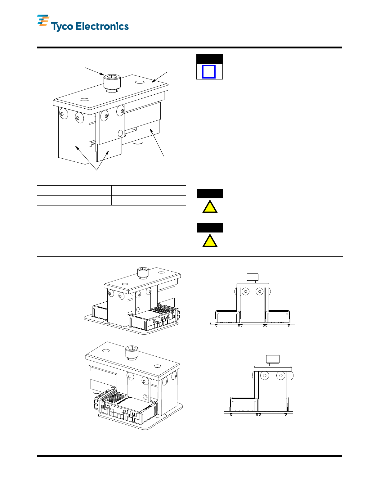
Extraction Screw
Upper Tooling
Assembly
Removal Blade
Assembly
Side Plates
Removal Tool
2161060-1
REMOVAL TOOL CONNECTOR DESCRIPTION
2161060-1 CXP Receptacle Assembly
Figure 1
Instruction Sheet
408-10415
14 DEC 10 Rev A
Dimensions in this instruction sheet are in
millimeters [with inches in brackets]. Figures and
illustrations are for reference only and are not
drawn to scale.
Read these instructions and understand them before
using the removal tool.
2. DESCRIPTION
The tool consists of a removal blade assembly, and an
upper tooling assembly. See Figure 1.
The side plates of the upper tooling assembly push on
the pc board surface while removing the receptacle.
The removal blade assembly engages the receptacle
and pulls it from the pc board. The extraction screw
draws the removal blade assembly up and pulls the
CXP receptacle assembly up and off of the pc board.
3. REMOVAL PROCEDURE
There are (4) M2 screws holding the receptacle
assembly to the pc board. These M2 screws must
be removed prior to removing the receptacle
assembly.
ORIGINAL INSTRUCTIONS
1. INTRODUCTION
The CXP Receptacle Assembly Removal Tool
2161060-1 is designed to remove the conne cto r listed
in Figure 1 from the printed circuit (pc) board.
Be certain to remove tool assembly does not
contact any components on the pc board during
use. To prevent damage, the side plates can be
routed to clear adjacent components. See Figure 2.
Figure 2
©2010 Tyco Electronics Corporation, Berwyn, PA
All Rights Reserved
TE logo and Tyco Electronics are trademarks.
*Trademark. Other products, logos, and company names might be trademarks of their respective owners.
TOOLING ASSISTANCE CENTER 1-800-722-1111
PRODUCT INFORMATION 1-800-522-6752
This controlled document is subject to change.
For latest revision and Regional Customer Service,
visit our website at www.tycoelectronics.com
1 of 2
LOC B
Page 2
1. Disassemble the upper tooling assembly and
removal blade assembly by unscrewing the
extraction screw.
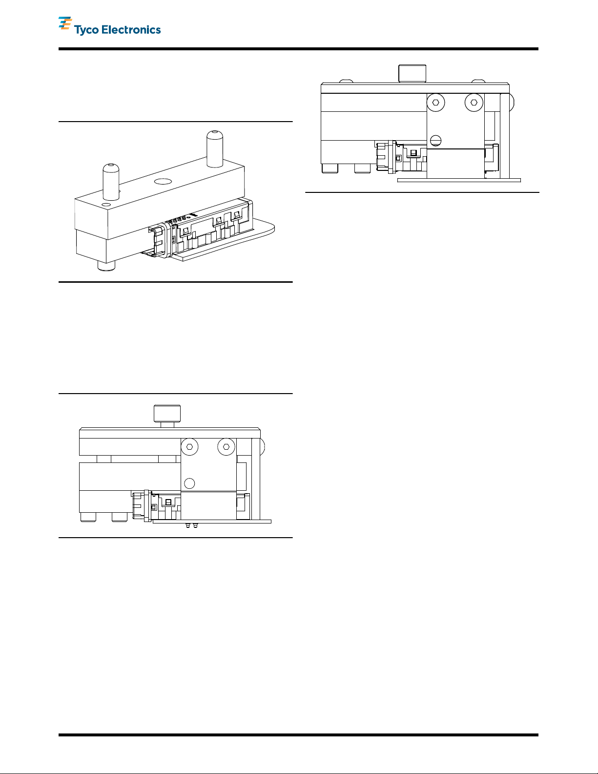
2. Insert the removal blade assembly into the
receptacle. See Figure 3.
Figure 3
3. Properly orient the side plate(s) of the upper
tooling assembly based on any adjacent receptacle
assembly(s). See Figure 2.
4. Position the upper tooling assembly over the pins
in the blade removal assembly. Lower the upper
tooling assembly until the side plates contact the pc
board. See Figure 4.
408-10415
Figure 5
4.1. Daily Maintenance
It is recommended that each operator be made aware
of, and responsible for, the following steps of daily
maintenance:
1. Remove dust, moisture, and other contaminants
with a clean, soft brush, or lint-free cloth. DO NOT
use objects that could damage the tool or any of its
components.
2. When the tool is not in use, store it in a clean, dry
area.
4.2. Periodic Inspection
Regular inspections should be performed by quality
control personnel. A record of scheduled inspections
should remain with the tool or be supplied to personnel
responsible for the tool. The inspection frequency
should be based on the amount of use, working
conditions, operator training and skill, and established
company standards.
Figure 4
5. Tighten the extraction screw to remove the
receptacle assembly from the pc board. See
Figure 5.
4. MAINTENANCE AND INSPECTION
It is recommended that the tool be inspected
immediately upon its arrival to ensure that it has not
been damaged during shipment.
5. REPLACEMENT AND REPAIR
Order tools through your representative, or call
1-800-526-5142, or send a facsimile of your purchase
order to 717-986-7605, or write to:
CUSTOMER SERVICE (038-035)
TYCO ELECTRONICS CORPORATION
PO BOX 3608
HARRISBURG PA 17105- 3608
For customer repair service, call 1-800-526-5136.
6. REVISION SUMMARY
•Initial release of document
Rev A
2 of 2
 Loading...