

Page 1
Operator’s Manual
MM-014713-001
Apr/08
M/A-COM
CS-7000 Control Station
Page 2

MM-014713-001
MANUAL REVISION HISTORY
REV DATE REASON FOR CHANGE
- Apr/08 Initial release.
M/A-COM Technical Publications would particularly appreciate feedback on any errors found in this document and
suggestions on how the document could be improved. Submit your comments and suggestions to:
Tyco Electronics Wireless Systems Segment or fax your comments to: 1 (434) 455-6851
M/A-COM, Inc.
Technical Publications or e-mail us at: techpubs@tycoelectronics.com
221 Jefferson Ridge Parkway
Lynchburg, VA 24501
ACKNOWLEDGEMENTS
This device is made under license under one or more of the following US patents: 4,590,473; 4,636,791; 5,148,482;
5,185,796; 5,271,017; 5,377,229; 4,716,407; 4,972,460; 5,502,767; 5,146,497; 5,164,986; 5,185,795. The voice coding
technology embodied in this product is protected by intellectual property rights including patent rights, copyrights, and trade
secrets of Digital Voice Systems, Inc. The user of this technology is explicitly prohibited from attempting to decompile,
reverse engineer, or disassemble the Object Code, or in any other way convert the Object Code into human-readable form.
The software contained in this device is copyrighted by M/A-COM, Inc. Unpublished rights are reserved under the copyright
laws of the United States.
CREDITS
MASTR and EDACS are registered trademarks and ProGrammer is a trademark of M/A-COM Inc.
All other brand and product names are trademarks, registered trademarks, or service marks of their respective holders.
NOTICE!
Repairs to this equipment should be made only by an authorized service technician or facility designated by the supplier.
Any repairs, alterations or substitutions of recommended parts made by the user to this equipment not approved by the
manufacturer could void the user's authority to operate the equipment in addition to the manufacturer's warranty.
This product conforms to the European Union WEEE Directive 2002/96/EC. Do not disp ose of this product in a
public landfill. Take it to a recycling center at the end of its life.
This manual is published by M/A-COM, Inc., without any warranty. Improvements and changes to this manual necessitated
by typographical errors, inaccuracies of current information, or improvements to programs and/or equipment, may be made
by M/A-COM, Inc., at any time and without notice. Such chang es will be incorp orated into new editio ns of this manu al. No
part of this manual may be reproduced or transmitted in any form or by any means, electronic or mechanical, including
photocopying and recording, for any purpose, without the express written permission of M/A-COM, Inc.
Copyright© 2008 M/A-COM, Inc. All rights reserved.
2
Page 3

MM-014713-001
TABLE OF CONTENTS
Section Page
1 SAFETY INFORMATION ..............................................................................................................5
1.1 SAFETY
CONVENTIONS.......................................................................................................5
2 GENERAL DESCRIPTION ............................................................................................................6
3 CONTROLS AND CONNECTIONS..............................................................................................7
3.1 LOCAL
CONTROL STATION................................................................................................ 7
3.1.1 DC Power Indicator.....................................................................................................7
3.1.2 Transceiver..................................................................................................................7
3.1.3 Local Speaker..............................................................................................................7
3.2 REMOTE
CONTROL STATION.............................................................................................7
3.2.1 Remote Station Microphone ........................................................................................ 8
3.2.2 Intercom Switch ..........................................................................................................8
3.2.3 Remote Switch and LED Indicator..............................................................................8
3.2.4 Station Volume Control...............................................................................................8
3.2.5 VU Meter.....................................................................................................................9
3.3 REMOTE
3.4 REAR
MOUNT STATION .................................................................................................9
PANEL FEATURES......................................................................................................9
3.4.1 AC Power Switch/Cord/Fuse Assembly .....................................................................9
3.4.2 Antenna Connector....................................................................................................10
3.4.3 Internal Fan................................................................................................................10
3.4.4 Earth Ground.............................................................................................................10
3.4.5 CAN Port...................................................................................................................10
3.4.6 Phone Line Connection (Optional)............................................................................10
3.4.7 Computer Connection................................................................................................10
3.4.8 LAN...........................................................................................................................10
3.4.9 Serial A......................................................................................................................10
3.4.10 Serial B......................................................................................................................11
3.4.11 External I/O...............................................................................................................11
4 CONTROL STATION OPERATION...........................................................................................12
4.1 POWERING
4.2 GENERAL
UP THE STATION............................................................................................12
OPERATION.......................................................................................................12
4.2.1 Setting Up And Using The Control Station Transceiver...........................................12
4.2.2 To Receive a Call (Local-Only Control Stations) .....................................................12
4.2.3 To Make (Transmit) a Call (Local-Only Control Stations).......................................12
4.2.4 To Receive a Call (Remote Controlled Stations) ......................................................12
4.2.5 To Make (Transmit) a Call (Remote Controlled Stations)........................................ 13
4.3 REMOTE
CONTROL OPERATION......................................................................................13
4.3.1 Enabling Remote Control..........................................................................................13
4.3.2 Disabling Remote Control.........................................................................................13
4.4 INTERCOM
OPERATION.....................................................................................................14
4.4.1 Continuous Intercom Operation (Intercom-Only Mode)...........................................14
4.4.2 Momentary Intercom Operation................................................................................14
3
Page 4

MM-014713-001
TABLE OF CONTENTS
Section Page
5 REFERENCE MATERIAL ...........................................................................................................15
6 INTERCOM AND REMOTE SWITCH SUMMARY ................................................................16
7 WARRANTY...................................................................................................................................17
TABLES
Table 5-1: Reference Documents ............................................................................................................ 15
Table 6-1: Summary of Remote and Intercom Switch Positions ............................................................16
FIGURES
Figure 2-1: CT-013892-001 Local Control Station with Scan Head (Front View)...................................6
Figure 2-2: CT-013892-002 Local/Remote Control Station with System Head (Front View) .................6
Figure 3-1: Front Panel Features – Local Control Station.........................................................................7
Figure 3-2: Front Panel Features – Remote Control Station .....................................................................9
Figure 3-3: Rear Panel Features – Local and Remote Stations...............................................................11
4
Page 5
1 SAFETY INFORMATION
1.1 SAFETY CONVENTIONS
The following conventions are used throughout this manual to alert the user to general safety precautions
that must be observed during all phases of operation, service, and repair of this product. Failure to comply
with these precautions or with specific warnings elsewhere in this manual violates safety standards of
design, manufacture, and intended use of the product. M/A-COM, Inc. assumes no liability for the
customer's failure to comply with these standards.
The WARNING symbol calls attention to a procedure, practice, or the like,
which, if not correctly performed or adhered to, could result in personal injury.
Do not proceed beyond a WARNING symbol until the conditions identified are
fully understood or met.
CAUTION
The CAUTION symbol calls attention to an operating procedure, practice, or the like,
which, if not performed correctly or adhered to, could result in a risk of danger,
damage to the equipment, or severely degrade the equipment performance.
MM-014713-001
The NOTE symbol calls attention to supplemental information, which may improve
system performance or clarify a process or procedure.
The ESD symbol calls attention to procedures, practices, or the like, which could
expose equipment to the effects of Electro-Static Discharge. Proper precautions must
be taken to prevent ESD when handling circuit modules.
The electrical hazard symbol is a WARNING indicating there may be an
electrical shock hazard present.
5
Page 6
MM-014713-001
2 GENERAL DESCRIPTION
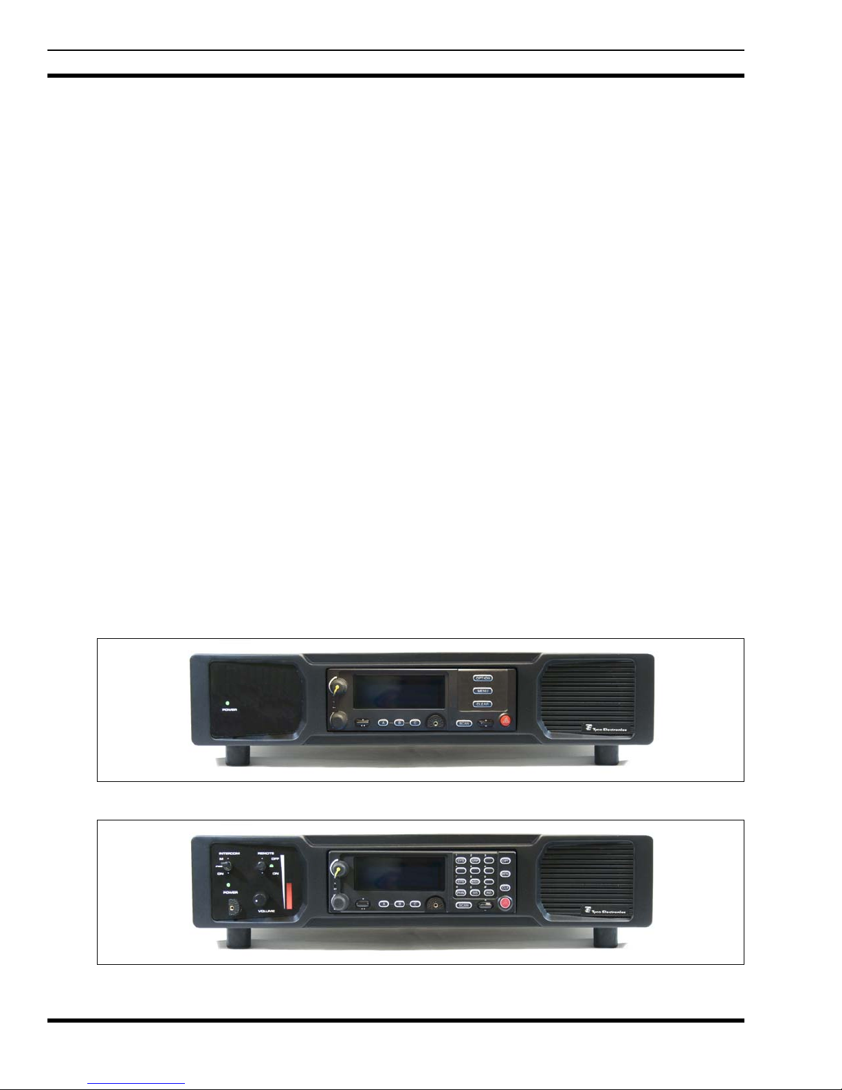
The M/A-COM CS-7000 Control Stations shown in Figure 2-1 and Figure 2-2 are state-of-the-art Control
Stations. The slimline design of the CS-7000 Control Station provides a convenient method to equip
offices, shops and other remote locations with radio communications.
At the heart of the CS-7000 Control Stations are the M5300 and M7300 transceiver. The M5300
transceiver is a single band transceiver capable of EDACS
®
, Conventional, and P25 modes of operation.
The M7300 transceiver is a dual band 700/800 MHz transceiver capable of EDACS, Conventional, P25,
and OpenSky
®
modes of operation. Both transceivers may be equipped with the Scan (Figure 2-1) or
System (Figure 2-2) model CH721 Control Head.
The CS-7000 Control Station may also be equipped with a remote interface board allowing remotely
located desktop station controllers to share radio communications with the local operation of the Desktop
Station.
The Desktop Station is available in the following three models:
• Desktop Station configuration with only local controls.
• Desktop Station configuration with local and remote control capability.
• Remote mount configuration with remote control capability.
Local Control Desktop Station model CT-013892-001 shown in Figure 2-1 is designed to provide local
control of an M5300 or M7300 transceiver (shown with a Scan Control Head) in a desktop control station
configuration.
Local/Remote Control Desktop Station model CT-013892-002 shown in Figure 2-2 is includes a built-in
remote controller board and front panel controls. This model is designed to provide local and remote
control operation.
Remote station model CT-013892-003 (not shown) features are similar to the Local/Remote Control
Desktop Station, however without a control unit or speaker, and with a blank faceplate and power LED.
Figure 2-1: CT-013892-001 Local Control Station with Scan Head (Front View)
Figure 2-2: CT-013892-002 Local/Remote Control Station with System Head (Front View)
6
Page 7

3 CONTROLS AND CONNECTIONS
3.1 LOCAL CONTROL STATION
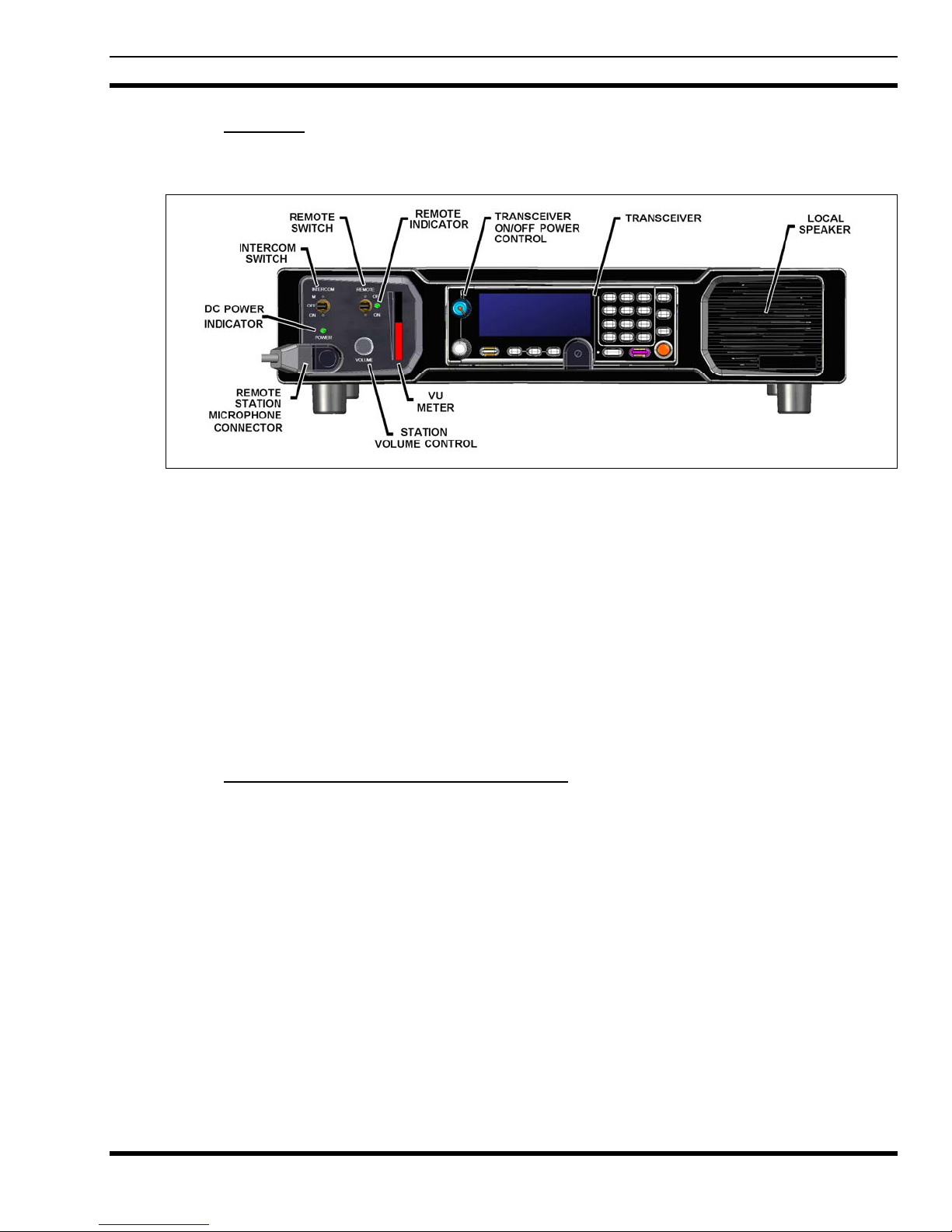
Front panel controls, indicators, and other operator features are shown in Figure 3-1. The following are
general descriptions of each feature.
3.1.1 DC Power Indicator
A DC power indicator is located on the front-left station panel. This indicator illuminates when the
station’s main built-in power supply is turned on and supplying DC voltage to Control Station.
3.1.2 Transceiver
The CS-7000 Control Station may be equipped with an M5300 or M7300 transceiver, respectively. The
M5300 transceiver is a single band transceiver capable of EDACS, Conventional and OpenSky modes of
operation. The M7300 transceiver is a dual band 700/800 MHz transceiver capable of EDACS,
Conventional, P25, and OpenSky modes of operation. Both transceivers include the CH721 control head.
3.1.2.1 Transceiver ON/OFF/Volume Control
Local Control Stations rely on the transceiver’s ON/OFF-Volume control for volume level setting. Refer
to Section 3.2.4 when setting the volume on remote control stations.
MM-014713-001
3.1.2.2 Local Microphone
The transceiver’s microphone connector shown in Figure 3-1 is used for local control stations. Refer to
Section 3.2.1 when connecting a microphone to a remote control station.
3.1.3 Local Speaker
The station contains a front firing local speaker for improved performance.
Figure 3-1: Front Panel Features – Local Control Station
3.2 REMOTE CONTROL STATION
In addition to the features found on the local control station, remote control stations include the features
described in the following sub-sections.
7
Page 8

MM-014713-001
3.2.1 Remote Station Microphone
The microphone for remote control stations is connected to the remote station microphone connector as
shown in Figure 3-2. See Section 3.1.2.2 when connecting a microphone to a local control station.
3.2.2 Intercom Switch
The Intercom switch places the Control Station in one of two intercom modes, or normal mode. The
Intercom switch may be set to one of the following three (3) settings:
M (UP - Momentary position): This is a spring loaded momentary position that places the local station in
the INTERCOM mode until the operator releases the switch, at which time it will return to the OFF
position. Holding the INTERCOM switch in the M position, and keying the Local Station Microphone,
will NOT key the transceiver. Local Station Microphone audio will be heard only at remote controllers
until the switch is released.
OFF (Center position): This position is the NORMAL mode. Transmissions made from the Local Station
Microphone will key the transceiver and transmit audio will be heard only over-the-air. Remote
controllers will also hear the Control Station’s Local Microphone audio if the REMOTE switch is set to
the ON position.
The Control Station’s microphone MUST be connected to the Control Station’s
remote station microphone connector found on the front-left faceplate panel.
Connecting the Control Station’s microphone to the transceiver will result in improper
operation of the remote control features.
ON (Down position): This position places the Control Station operation in the INTERCOM mode.
Transmissions made from the Local Station Microphone will NOT key the transceiver, Local Station
Microphone audio will be heard only by Remote Controllers, and transmissions made by Remote
Controllers will only be heard over the Local Speaker (Remote Controller transmissions will not key the
transceiver).
3.2.3 Remote Switch and LED Indicator
The Remote switch provides the local control operator the ability to enable access by remote controllers.
The Remote switch may be set to one of the following two (2) settings:
ON (Down position): This position is the NORMAL mode of operation. It enables Remote Controller
access to the Control Station and illuminates the Remote Indicator LED. Remote Controllers will be able
to transmit or receive over-the-air via the Control Station’s transceiver.
OFF (UP position): This position disables radio access to and from Remote Controllers. In this position,
Remote Controllers will not be able to transmit or receive over the Control Station’s radio.
The Remote Switch must be set to the ON position to allow remote controllers to transmit
and receive over-the-air via the Control Station’s transceiver.
3.2.4 Station Volume Control
The Station Volume Control functions as the Control Station’s master volume control on stations
equipped with the remote control option. The volume control setting for the transceiver is preprogrammed to a fixed level to ensure proper Control Station operation in remote applications.
8
Page 9
MM-014713-001
3.2.5 VU Meter
Control Station is equipped for remote control operation also includes a VU Meter. The VU Meter
displays, in bar graph format, line audio levels to and from remote controllers.
Figure 3-2: Front Panel Features – Remote Control Station
3.3 REMOTE MOUNT STATION
The CS-7000 Remote Mount Station (not shown) is designed for applications where access to local user
controls is not required. The Remote Mount Station is housed in a 2-RU high rack mountable enclosure
and equipped only with a front panel power LED. Rear panel features are as described in Section 3.4.
This model is fully remote controlled and does not include any front panel user controls, a control unit,
rubber feet, or a front panel speaker.
3.4 REAR PANEL FEATURES
All versions of the CS-7000 Control Station share similar rear panel features. The following sub-sections
provide a brief description of the available rear panel features.
3.4.1 AC Power Switch/Cord/Fuse Assembly
The AC Power Switch/Cord/Fuse assembly is located on the left side of the rear panel when facing the
rear panel. As indicated it serves as the main Control Station ON/OFF switch, AC cord receptacle, and
houses the fuses for the main AC line input. This switch controls AC power to the 120/240, 50/60 Hz
internal AC power supply.
3.4.1.1 AC Power Switch
The main AC Power Switch for the Control Station is located on the left side of the rear panel (when
facing the rear panel), and is part of the AC Power Switch/Cord/Fuse assembly.
3.4.1.2 AC Power Cord Receptacle
The AC Power Cord receptacle for the Control Station is located on the left side of the rear panel (when
facing the rear panel) and is part of the AC Power Switch/Cord/Fuse assembly. The receptacle is an
industry standard IEC-302 type 3-pin power connector.
9
Page 10

MM-014713-001
3.4.1.3 AC Fuse
The main AC power fuses for the Control Station are located on the left side of the rear panel (when
facing the rear panel) and is part of the AC Power Switch/Cord/Fuse assembly. Caution should be taken
when replacing a suspected blown fuse to ensure the proper value replacement fuse is re-installed. Fuse
replacement should only be attempted by authorized service personnel.
3.4.2 Antenna Connector
The Control Station antenna connector located on the rear panel is a 50 ohm Type-N female panelmounted connector. Care must be taken to ensure proper antenna connections at all times.
3.4.3 Internal Fan
The Control Station employs an internal cooling fan which is mounted inside the cabinet near the center
of the rear panel. The fan opening must at all times be kept clean and free of objects that potentially
block the free flow of air.
3.4.4 Earth Ground
The Earth Ground connection is a #10-32 stud used to help dissipate any stray electrical currents away
from the station and to earth ground. This connection should be made before applying AC power to the
Control Station.
3.4.5 CAN Port
The Controller Area Network (CAN) port is similar to standard serial ports and supports full-duplex
connectivity to optional M/A-COM devices. However, unlike standard serial ports, multiple CAN
devices may share a common CAN bus. A CAN bus is limited to a maximum distance of 250 ft. between
the two furthest devices connected to the CAN bus. The Control Station can be connected anywhere
along the bus. A fiber optic CAN bus extender may be used when CAN bus distances greater than 250
feet is required.
3.4.6 Phone Line Connection (Optional)
The Phone Line connection is an RJ-11 type connection used to connect remotely located tone remote
controllers to the station via a 2-wire or 4-wire dedicated phone line.
3.4.7 Computer Connection
The Computer connection is an RJ-45 type Ethernet port. This port is used to communicate locally with
the Control Station via PC for programming, while the LAN port is connected to a Voice-over-Internet
Protocol (VoIP) controller network.
3.4.8 LAN
The LAN connection is an RJ-45 type Ethernet port. This port is used to connect the desktop to a VoIP
controller network. The controllers may access Control Station functions, commands, and handle
transmit and receive audio as IP packets making this a superior option for users with IP connectivity.
3.4.9 Serial A
The Serial A connection is a USB Type B connection, and used to access the transceiver’s serial USB
programming port.
10
Page 11

MM-014713-001
3.4.10 Serial B
The Serial B connection is a DB-9 DCE female connection, and used to access the transceiver’s serial Rs232 programming port.
3.4.11 External I/O
The External I/O connector is a DB-25 female connection. This port provides access to local controlling
features of the transceiver such as PTT, TX audio, RX audio, etc. Foot switches and other local external
customer devices may be connected to the Control Station using this connector.
Figure 3-3: Rear Panel Features – Local and Remote Stations
11
Page 12

MM-014713-001
4 CONTROL STATION OPERATION
4.1 POWERING UP THE STATION
1. Make sure the Control Station is connected to a functional AC power outlet.
2. On the Control Station’s rear panel (refer to Figure 3-3), turn on the main ON/OFF power switch
located just above the AC power cord. The front panel Power Indicator should be illuminated green.
3. Turn on the transceiver’s ON/OFF Power switch (refer to Figure 3-1).
4.2 GENERAL OPERATION
4.2.1 Setting Up And Using The Control Station Transceiver
Receiving and transmitting a message is affected by how the transceiver installed into the Control Station
is programmed, and how the supporting communications system operates. Refer to the specific Mobile
Radio Operator’s Manual or Quick Guide for a detailed description and operation for the transceiver
installed in the Control Station. Contact your local system administrator or other trained and qualified
operators for system information.
4.2.2 To Receive a Call (Local-Only Control Stations)
1. Set the transceiver to the desired System, Group, or Channel (depends on radio programming) using
the System/Group or Channel knob. The Control Station is now ready to receive messages from other
radios in the system.
2. When the first call is received, it may be necessary to adjust the VOLUME control to the desired
listening level. Use the transceiver’s VOLUME control to set the volume level.
4.2.3 To Make (Transmit) a Call (Local-Only Control Stations)
1. If more than one channel is available, select the proper channel using the radio’s System/Group
Channel knob.
2. For conventional (non-trunked) systems, press the monitor button on the microphone and listen to
make sure no one else is using the channel.
3. Press the PTT switch on the microphone, and then speak into the microphone using a normal
speaking voice. Always release the PTT switch as soon as the message is completed, and listen for an
answer to the call.
4.2.4 To Receive a Call (Remote Controlled Stations)
1. Set the transceiver to the desired system, group, or channel (depends on radio programming) using the
System/Group/Channel knob.
2. Set the REMOTE switch on the Control Station to the ON (down) position so remote controllers can
also hear received messages. The Control Station is now ready to perform the following:
• Receive messages over-the-air from other radios in the system.
• Pass the received signal to remote controllers connected to the Control Station.
• Receive transmissions from remote controllers.
12
Page 13
3. When the first call is received, it may be necessary to adjust the volume control to the desired
listening level. Use the Station Volume Control to set to local speaker volume level. Setting this
control does not affect the volume level heard by remote controllers.
4.2.5 To Make (Transmit) a Call (Remote Controlled Stations)
1. If more than one channel is available, select the proper channel using the radio’s
System/Group/Channel knob.
2. Set the REMOTE switch to the ON (down) position to allow remote controllers to key the Control
Station.
3. The Control Station is now ready to transmit messages over-the air from remote controllers connected
to the Control Station.
4. For conventional (non-trunked) systems, press the monitor button on the microphone, or set the
INTERCOM switch to the M (up) position and listen to make sure no one else is using the channel.
5. Press the PTT switch on the microphone, and then speak into the microphone using a normal
speaking voice. Always release the PTT switch as soon as the message is completed, and listen for an
answer to the call.
4.3 REMOTE CONTROL OPERATION
MM-014713-001
Control Stations equipped with Intercom and Remote switches may be remotely controlled. The Intercom
and Remote switches determine when remote controllers connected to the Control Station may send and
receive messages via the Control Station.
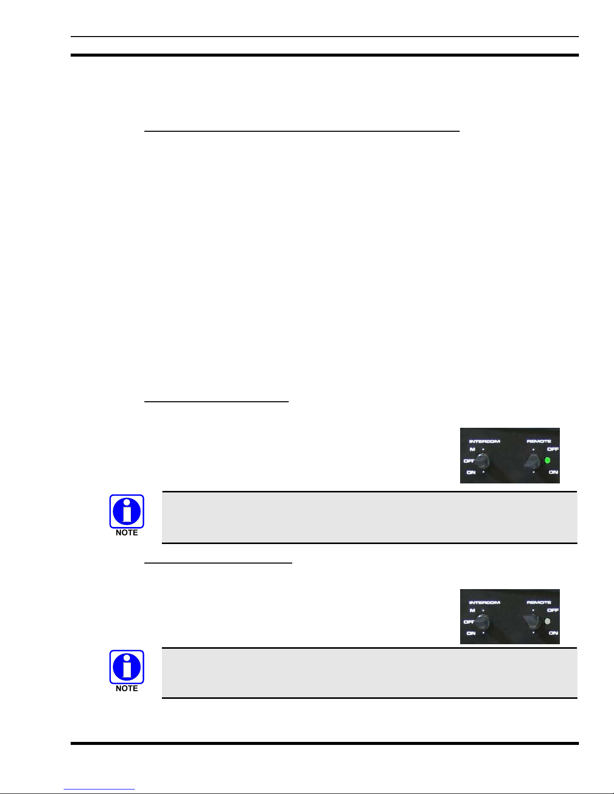
4.3.1 Enabling Remote Control
Perform the following steps to enable Remote Control Capability:
1. Make sure the Control Station is powered up (refer to Section 4.1).
2. Set the INTERCOM switch to the OFF (center) position.
3. Set the REMOTE switch to the ON (down) position.
Setting the INTERCOM switch to OFF (center) position and the REMOTE switch to ON
(down) position is typically the NORMAL mode of operation for remote control
equipped Control Stations.
4.3.2 Disabling Remote Control
Perform the following steps to disable Remote Control operation:
1. Make sure the Control Station is powered up (see Section 4.1).
2. Set the INTERCOM switch to the OFF (center) position.
3. Set the REMOTE switch to the OFF (up) position.
Setting the REMOTE switch to the OFF position disables communications to and from
remote controllers including intercom operation.
13
Page 14

MM-014713-001
4.4 INTERCOM OPERATION
Control Stations equipped with Intercom and Remote switches may make intercom calls to and from
remote controllers connected to the Control Station. The Intercom and Remote switches determine when
and how the Control Station makes intercom calls.
4.4.1 Continuous Intercom Operation (Intercom-Only Mode)
The Continuous Intercom mode of operation allows transmissions between the Control Station and
Remote Controllers (over-the-air transmissions via the Control Station are disabled during this mode).
Perform the following steps to make an Intercom call:
1. Make sure the Control Station is powered up (see Section 4.1).
2. Set the INTERCOM switch to the ON position.
3. Set the REMOTE switch to the OFF position.
4. Press and hold the PTT switch on the Local Station Microphone at the beginning of each
transmission. Release the PTT switch at the end of each transmission.
In the Continuous Intercom mode, neither audio from the Local Station Microphone or a
remote controller will be transmitted over-the-air. Only intercom communications is
possible!
4.4.2 Momentary Intercom Operation
The M position on the Intercom switch is spring-loaded (momentary) and returns the switch to the OFF
position when released. This switch position allows the Control Station’s local operator to make an
intercom call without leaving the Control Station in continuous intercom mode. This is a convenient
position to use since the ON position disables over-the-air transmissions from the Control Station.
Perform the following steps to make a Momentary Intercom call:
1. Make sure the Control Station is powered up (see Section 4.1).
2. Set the INTERCOM switch to the M position.
3. Set the REMOTE switch to the OFF position.
4. Press and hold the PTT switch on the Local Station Microphone at the beginning of each
transmission. Release the PTT switch at the end of each transmission.
5. Release the INTERCOM switch when the intercom call is complete.
Audio from the Local Station Microphone or a remote controller will NOT be transmitted
over-the-air during this switch configuration. Only intercom communications are possible!
14
Page 15

5 REFERENCE MATERIAL
It may be necessary to consult one or more of the following manuals. These manuals will also provide
additional guidance if you encounter technical difficulties during the installation or testing processes.
Table 5-1: Reference Documents
DOCUMENTATION MANUAL NUMBER
CS-7000 Installation Manual MM-014714-001
M5300 Transceiver Operator’s Manual MM-012125-001
M5300 Transceiver Quick Guide when using OpenSky Systems MM-012997-001
MM-014713-001
M5300 Transceiver Quick Guide when using P25, EDACS, or
Conventional Systems
M7300 Transceiver Operator’s Manual MM-014718-001
M7300 Transceiver Quick Guide when using OpenSky Systems MM-014368-001
M7300 Transceiver Quick Guide when using P25, EDACS, or
Conventional Systems
MM-013232-001
MM-014369-001
15
Page 16

MM-014713-001
6 INTERCOM AND REMOTE SWITCH SUMMARY
Table 6-1: Summary of Remote and Intercom Switch Positions
SWITCH
POSITIONS
INTERCOM AND
REMOTE ENABLED
INTERCOM-ONLY
(REMOTE DISABLED)
REMOTE ENABLED
PTT BUTTON1
STATUS
Receive Mode
(No PTTs Pressed).
PTT on Control Station
Microphone Pressed.
Intercom Mode Selected
on the Remote Controller
and PTT Pressed.
Transmit Channel Selected
on the Remote Controller
and PTT Pressed.
Receive Mode
(No PTTs Pressed).
PTT on Control Station
Microphone Pressed.
Remote Controller PTT
PTT on Control Station
Intercom Mode Selected
on the Remote Controller
Transmit Channel Selected
on the Remote Controller
Pressed.
Receive Mode
(No PTTs Pressed).
Microphone Pressed.
and PTT Pressed.
and PTT Pressed.
TRANSMIT
PRIORITY2
N/A
1
2
2
N/A
1
2
N/A
1
2
2
COMMENTS
The Control Station’s receiver audio is
heard at the Control Station’s speaker, and
Remote Controller’s speaker.
Audio from Control Station’s microphone is
heard at the Remote Controller’s speaker.
Audio from Remote Controller’s
microphone is heard at the Control
Station’s speaker.
Audio from Remote Controller’s
microphone is heard at the Control
Station’s speaker, and transmitted overthe-air.
The Control Station’s receiver audio is
heard at the Control Station’s speaker.
Audio from Control Station’s microphone is
heard at the Remote Controller’s speaker.
Microphone audio from Remote Controller
is heard at the Control Station’s speaker.
The Control Station’s receiver audio is
heard at its speaker, and Remote
Controller’s speakers.
Audio from Control Station’s microphone is
heard at Remote Controller’s speaker, and
transmitted over-the-air.
Microphone audio from Remote Controller
is heard at the Control Station’s speaker.
Audio from Remote Controller’s
microphone is heard at the Control
Station’s speaker, and transmitted overthe-air.
1
REMOTE DISABLED
1. Regarding all PTT actions, it is possible for the Control Station to be programmed to hinder all PTT actions when its
receiver is unmuted (receiving an over-the-air call). PTT actions are restored once the receiver is muted.
2. PTT actions from the Control Station’s microphone will always take precedence over PTT requests form Remote
Controllers.
16
Receive Mode
(No PTTs Pressed).
PTT on Control Station
Microphone Pressed.
N/A
1
The Control Station’s receiver audio is
heard at the Control Station’s speaker.
Audio from the Control Station’s
microphone is transmitted over-the-air.
Page 17

MM-014713-001
7 WARRANTY
A. M/A-COM, Inc. (hereinafter "Seller") warrants to the original purchaser for use (hereinafter "Buyer") that Equipment
manufactured by or for the Seller shall be free from defects in material and workmanship, and shall conform to its
published specifications. With respect to all non-M/A-COM Equipment, Seller gives no warrant y, and only the warranty, if
any, given by the manufacturer shall apply. Rechargeab le batteries are excluded from this warranty but are warranted
under a separate Rechargeable Battery Warranty (ECR-7048).
B. Seller’s obligations set forth in Paragraph C below shall apply only to failures to meet the above warranties occurring
within the following periods of time from date of sale to the Buyer and are conditioned on Bu yer’s giving written notice to
Seller within thirty (30) days of such occurrence:
1. for fuses and non-rechargeable batteries, operable on arrival only.
2. for parts and accessories (except as noted in B.1) sold by Seller’s Service Parts Operation, ninety (90) da ys.
3. for P7200, P7100IP, P5400, P5300, P5200, P5100, P3300, PANTHER™ 405P and 605P, M7300, M7200 (incl uding
V-TAC), M7100 IP, M5300 and M3300 radios, two (2) years.
4. for all other equipment of Seller’s manufacture, one (1) year.
C. If any Equipment fails to meet the foreg oing warranties, Seller shall correct the failure at its option (i) by repairing any
defective or damaged part or parts thereof, (ii) by making available at Seller’s factory any necessary repaired or
replacement parts, or (iii) by replacing the failed Equipme nt with equivalent new or refurbished Equipm ent. Any repaired
or replacement part furnished hereunder shall be warranted for the remainder of the warranty period of the Equi pment in
which it is installed. Where such failure cannot b e corrected by Seller’s reasonable efforts, the parties will negotiate an
equitable adjustment in price. Labor to perform warranty ser vice will be provided at no charge duri ng the warranty period
only for the Equipment covered under Paragraph B.3 and B.4. To be eligible for no-charge labor, service must be
performed at a M/A-COM factory, by an Authorized Service Center (ASC) or oth er Servicer approved for thes e purposes
either at its place of business during normal business hours, for mobile or personal equipment, or at the Buyer’s location,
for fixed location equipment. Service on fixed locatio n equipment more than thirty (30) miles from the Service Center or
other approved Servicer’s place of business will include a charge for transportation.
D. Seller’s obligations under Paragraph C shall not apply to an y Equipment, or part thereof, which (i) has been modified or
otherwise altered other than pursuant to Seller’s written instruct ions or written approval or, (ii) is normally consumed in
operation or, (iii) has a normal life inherently shorter than the warranty periods specified in Paragraph B, or (iv) is not
properly stored, installed, used, maintained or repaired, or, (v) has been subjected to any other kind of misuse or
detrimental exposure, or has been involved in an accident.
E. The preceding paragraphs set forth the exclusive remedies for claims based upon defects in or nonconformity of the
Equipment, whether the claim is in contract, warranty, tort (including neglig ence), strict liability or otherwise, and ho wever
instituted. Upon the expiration of the warranty period, all such liability shall terminate. The foregoing warranties are
exclusive and in lieu of all other warranties, whether oral, written, expressed, implied or statutory. NO IMPLIED OR
STATUTORY WARRANTIES OF MERCHANTABILITY OR FITNESS FOR PARTICULAR PURPOSE SHALL APPLY. IN
NO EVENT SHALL THE SELLER BE LIABLE FOR ANY INCIDENTAL, CONSEQUENTIAL, SPECIAL, INDIRECT OR
EXEMPLARY DAMAGES.
M/A-COM, Inc. M/A-COM, Inc.
1011 Pawtucket Blvd. 221 Jefferson Ridge Parkway
Lowell, MA 01853 Lynchburg, VA 24501
1-877-OPENSKY (673-6759) 1-800-528-7711
Ref: ECR-7047E
17
This warranty applies only within the United States.
Page 18

Tyco Electronics Wireless Systems Segment
221 Jefferson Ridge Parkway
Lynchburg, Virginia 24501
(Outside USA, 1-434-385-2400) Toll Free 1-800-528-7711
www.macom-wireless.com Printed in U.S.A.
 Loading...