

Page 1
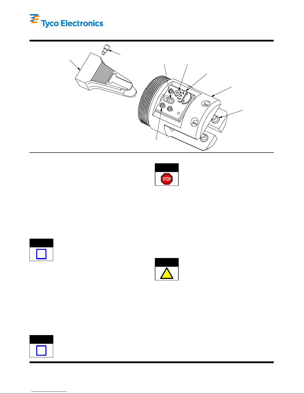
Cam
Pneumatic CERTI- CRIMP* Tool
Holder 356304 - 1 (For Use with 626
Eccentric
Cam
Setscrew
Ratchet
Pawl
Adjustment
Screw
Instruction Sheet
408--4321
11 MAR 10 Rev CPneumatic Tooling Assemblies)
Adjustable
Eccentric
Tool Holder
Body
Applicable Crimp Head Adapters:
Straight Action Crimper 217200--1
Heavy--Head Pneumatic Adapter 318453--1
Modular Plug Adapter 318510--1
Straight Action Crimp Head Adapter 217201--1
“T”--HEAD* Pneumatic Adapter 217202--1
C--Head Pneumatic Adapter 318161--1
Securing Screw (3 Places)
Figure 1
1. INTRODUCTION
Pneumatic CERTI--CRIMP Tool Holder 356304--1 is
used in conjunction with 626 Pneumatic T ooling
Assemblies 189721--1 or 189722--1 to crimp various
types of connectors. The tool holder is designed to
accept interchangeable crimp head adapters (listed in
Figure 1) which hold various crimping die assemblies.
For questions concerning the setup and operation of
the pneumatic tools, refer to Customer Manual
409--5862.
Read these instructions thoroughly before installing
the crimp head adapters and using the tool holder.
NOTE
i
Reasons for reissue of this sheet are provided in
Section 7, REVISION SUMMARY.
Dimensions are in millimeters [with inch
equivalents in brackets]. Figures and illustrations
are for identification only and are not drawn to
scale.
2. DESCRIPTION (Figure 1)
The tool holder consists of a tool holder body, cam,
cam setscrew, adjustable eccentric, pivot pins, and
ratchet pawl with emergency release. The ratchet
ensures that the tool completes the crimp cycle.
Pivot Pin
(4 Places)
DANGER
If the piston is not extended, it must first be extended
to allow installation of the cam. To extend the piston,
firmly grasp the piston with piston pliers and pull away
from the body of the tool. Piston pliers are provided
with the power unit.
A strip of adhesive--backed safety labels, printed in
various languages, is packaged with the tool holder.
Remove the appropriate language label from the strip
and attach it to the tool holder body.
CAUTION
!
Proceed as follows:
1. If cam setscrew is not installed in cam, thread
setscrew into cam two to three turns. See Figure 2.
Air pressure must be removed from the tool while
head or tool holder is detached.
Be sure to use the correct combination of cam
and tool holder. If incorrect combination is used,
system will not operate properly.
ORIGINAL INSTRUCTIONS
3. INSTALLATION PROCEDURE
3.1. Tool Holder Installation
NOTE
i
E2010 Tyco Electronics Cor poration, Berwyn, PA
All Rights Reserved
TE logo and Tyco Electronics are trademarks.
*Trademark. Other product names, logos, or company names might be trademarks of their respective owner s.
Previously installed cams and tool holders must
be removed before installing different ones.
Removal is the reverse of installation.
2. Place cam (with setscrew) onto piston rod. The
cam should butt against the piston rod face. If not,
turn cam setscrew counterclockwise until cam fits
on piston rod properly.
3. Tighten cam setscrew, then pull on cam to
ensure that it is firmly attached.
TOOLING ASSISTANCE CENTER 1--800--722-- 1111
PRODUCT INFORMATION 1--800--522--6752
This controlled document is subject to change.
For latest revision and Regional Customer Service,
visit our website at www.tycoelectronics.com
1 of 4
LOC B
Page 2
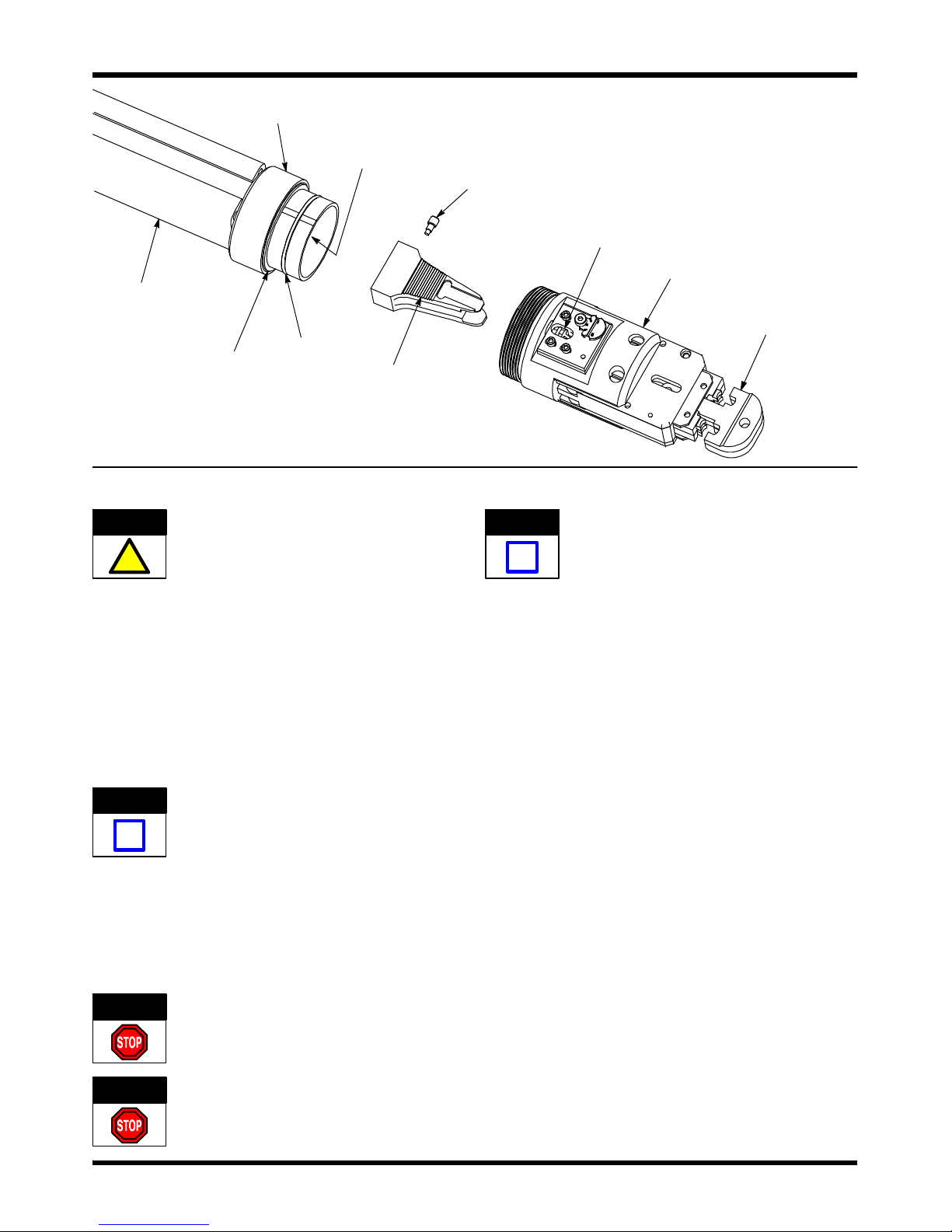
Pneumatic CERTI- CRIMP Tool Holder 356304- 1
Locking
Ring
Piston
Rod
Cam
Setscrew
Ratchet
Pawl
408- 4321
Tool
Holder
Pneumatic Tooling
Assembly (Power
Unit) (Ref)
Friction
Ring
Cam
Teeth
CAUTION
Stop
Ring
Over--tightening the cam setscrew may damage
the setscrew or cam.
!
4. Properly align tool holder ratchet pawl with the
cam teeth and push tool holder onto power unit so
that it passes over the friction ring on the power
unit piston. See Figure 2.
5. Slide power unit locking ring toward tool holder
until it butts against the stop ring on the power unit.
Then turn ring clockwise to engage threads on the
bottom of the tool holder. Tighten locking ring to
fully secure the tool holder.
NOTE
i
6. Rotate the tool holder one full turn in each
direction and note that the power unit locking ring
rotates with the tool holder.
DANGER
When tool holder is properly installed, the locking
ring should be butted against the stop ring, and
threads of the tool holder should not be visible. If
not properly installed, check that correct
combination of cam and tool holder is used and
that they are aligned properly.
T o avoid personal injury, periodically check that
locking ring is tightly securing the tool holder.
Crimp Head
Adapter (Ref)
Figure 2
NOTE
Removal is the reverse of installation.
i
3.2. Crimp Head Adapter and Crimping Die Installation
Refer to the instruction sheet packaged with the crimp
head adapter for the particular product to be crimped.
4. CRIMP HEIGHT ADJUSTMENT
The tool holder features an adjustable eccentric and a
ratchet mechanism with a range of settings. The
position of the pawl ensures that the tool completes
the cycle. The eccentric controls the amount of cam
pressure exerted on the crimping dies during the
crimping procedure. Although the ratchet is preset
prior to shipment, it is important that you verify the
crimp height. Also, general use and subsequent wear
may cause the tool to go out of adjustment. It is
recommended that the crimp height be inspected, and
adjusted, if necessary, on a regular basis by quality
control personnel.
1. Connect pneumatic tooling to an adequate air
supply between 620--690 kPa [90--100 psi]. For
specific information on air line requirements and air
hose installation, refer to the instructions packaged
with the pneumatic tooling assembly.
2. Place a contact in the crimp nest and place a
properly prepared wire of the correct size into the
wire barrel.
DANGER
After installation, ALWAYS ensure that the tool
holder pivot pins are fully tightened to avoid
personal injury or damage to the tool.
3. Place a .025--mm [.001--in.] shim between the
crimping dies where the dies bottom against each
other.
Rev C2 of 4 Tyco Electronics Corporation
Page 3

Pneumatic CERTI- CRIMP Tool Holder 356304- 1
408- 4321
4. Slowly crimp the contact onto the wire until the
crimping dies bottom on the shim. Check that the
ratchet releases after the dies bottom.
DANGER
5. If the ratchet releases before the dies bottom,
loosen the three securing screws, remove the
eccentric adjustment screw (refer to Figure 1) and
rotate the eccentric clockwise to a higher setting.
Tighten the securing screws. Repeat as required.
NOTE
i
Ratchet Pawl with
Emergency Release
6. If the ratchet does not release after the crimping
dies bottom, loosen the three securing screws,
remove the eccentric adjustment screw and rotate
the eccentric counterclockwise to a lower setting.
Tighten the securing screws. Repeat as required.
7. If the crimp cannot be made to conform to the
dimensions provided in the appropriate application
specification, the crimp head adapter and/or
crimping dies are defective and must be replaced.
Before adjusting the ratchet pawl position,
DISCONNECT THE TOOL FROM THE AIR
SUPPL Y. After the adjustment, ALWAYS ensure
that the tool holder pivot pins are fully tightened
to avoid personal injury or damage to the tool.
If the ratchet does not release and the tool will
not return, slowly actuate the tool until the force
of the cam teeth is off the pawl, then push on the
pawl with a small screwdriver until the pawl is
released from the teeth, release the tool switch
and allow the tool to return. See Figure 3.
Press Pawl with
Screwdriver
Figure 3
5. MAINTENANCE AND INSPECTION
DANGER
Tyco Electronics recommends that a maintenance
and inspection program be performed periodically to
H Trademark of Dow Corning Corporation
To avoid injury, DISCONNECT TOOL FROM AIR
SUPPL Y before performing any maintenance or
inspection procedures.
ensure dependable and uniform terminations. The
tool holder should be inspected once a week.
Frequency of inspection should be adjusted to suit
your requirements through experience, and depends
on:
S Care, amount of use, and handling of tool
holder
S Type and size of the products crimped
S Degree of operator skill
S Presence of abnormal amounts of dust and dirt
S Your own established standards.
The tool holder is thoroughly inspected before
packaging. Since there is the possibility of damage
during shipment, the tool holder should be inspected
immediately upon arrival at your facility.
5.1. Maintenance
A. Cleaning
Remove dust, moisture, and other contaminants with
a clean, soft brush, or a soft, lint--free cloth. Do NOT
use objects that could damage the tool. Lubricate tool
holder as instructed in Paragraph 5.1,B, Lubrication,
before placing the it back into service.
B. Lubrication
Lubricate all pins, pivot points, and bearing surfaces
with a high quality grease. Tyco Electronics
recommends the use of MolykoteH grease, which is a
commercially available lubricant. Lubricate according
to the following schedule:
Holder used in daily production—lubricate daily
Holder used daily (occasional)—lubricate weekly
Holder used weekly—lubricate monthly
Wipe excess grease from tool holder, particularly from
die closure areas. Grease transferred from the die
closure area onto certain terminations may affect the
electrical characteristics of an application.
5.2. Periodic Inspection
Regular inspections of the tool holder should be
performed by quality control personnel. A record of
scheduled inspections should remain with the tool
holder or be supplied to supervisory personnel
responsible for the tool holder. Inspection frequency
should be based upon amount of use, working
conditions, operator training and skill, and established
company standards.
1. Inspect the tool holder for missing pins or parts.
If parts are missing or defective, replace them by
referring to Figure 4.
2. Check all bearing surfaces for wear. Replace
any worn parts.
3. Inspect crimping dies for flattened, chipped, or
broken areas. Worn or damaged surfaces are
objectionable and will affect the quality of the
crimp.
3 of 4Rev C Tyco Electronics Corporation
Page 4

Pneumatic CERTI- CRIMP Tool Holder 356304- 1
408- 4321
4. When the tool holder is not in use, store in a
clean, dry area.
6. REPLACEMENT AND REPAIR
Replacement parts and recommended spares are
listed in Figure 4. The recommended spares should
be stocked for immediate replacement. Order
replacement parts through your Tyco Electronics
Representative or call 1--800--526--5142, or send a
facsimile of your purchase order to 1--717--986--7605,
or write to:
10
CUSTOMER SERVICE (38--35)
TYCO ELECTRONICS CORPORATION
PO BOX 3608
HARRISBURG PA 17105--3608
Tools may also be returned to Tyco Electronics for
evaluation and repair. For tool repair service, contact
a Tyco Electronics Representative at:
1--800--526--5136.
7. REVISION SUMMARY
The following changes were made since the previous
release of this sheet:
S Updated document to corporate requirements
S Added ORIGINAL INSTRUCTIONS
9
2
6
1
4
REPLACEMENT PARTS AND RECOMMENDED SPARE PARTSG
ITEM PART NUMBER DESCRIPTION
1 356623--1 CAM 1
2 356439--1 ECCENTRIC 1
3 356624--1 TOOL HOLDER BODY 1
4 356441--1 PAWL, Ratchet 1
5 4--21028--9 PIN, Slotted Spring, .125 x .375 1
6
7 356437--1 PLATE, Eccentric Adjustment 1
8 9--21000--0 SCREW, Socket Head Cap, 4--40 x .31 3
9 21989--3 SCREW, Socket Head Shoulder, .125 x .25 1
10
11 37887 SPRING 1
354425--1G
189765--1G
PIN, Pivot 4
SETSCREW, Special 1
Figure 4
8
5
7
11
3
QTY PER
TOOL HOLDER
Rev C4 of 4 Tyco Electronics Corporation
 Loading...