

Page 1
Instruction Sheet
NOTE
i
NOTE
i
NOTE
i
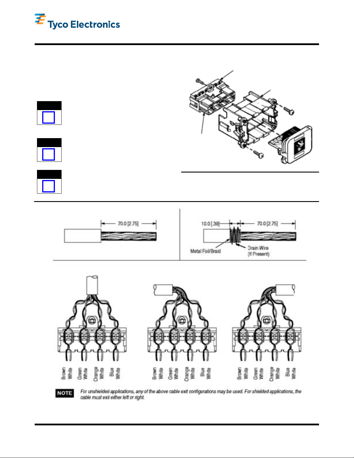
Cover
Single Port
Housing
110Connect
Card Edge
Connector
Unshielded Applications Shielded Applications
Exit Left Exit Right
AMP Communications Outlet (ACO)
Single Port Kits (Cat 6)
1. INTRODUCTION
This instruction sheet provides termination and
installation procedures for ACO Single Port Kits. The
kits can be used in panel mount or furniture raceway
applications. Optional faceplate kits and various
adapter insert assemblies are available to meet either
application.
Dimensions on this sheet are in millimeters [with
inches in brackets]. Figures are not drawn to scale.
2. TERMINATION PROCEDURES
The 110Connect card edge connector comes preinstalled in a single port housing. The single port
housing functions as a secure holding fixture while
terminating.
The edge connector is approved for use with 22
through 24 AWG solid wire with a maximum outside
insulation diameter of 1.6 mm [.06 in.] (100 ohm
UTP or STP).
408-8700
05 JAN 11 Rev A
Figure 1
Figure 2
©2011 Tyco Electronics Corporation, Berwyn, PA
All Rights Reserved
TE logo and Tyco Electronics are trademarks.
*Trademark. Other products, logos, and company names might be trademarks of their respective owners.
TOOLING ASSISTANCE CENTER 1-800-722-1111
PRODUCT INFORMATION 1-800-522-6752
This controlled document is subject to change.
For latest revision and Regional Customer Service,
visit our website at www.tycoelectronics.com
1 of 4
LOC B
Page 2
408-8700
NOTE
i
NOTE
i
Housing
Latch
Pins
Cover
47.75 [1.88]
(Approx)
33.27 [1.31]
(Approx)
Panel
Cutout
2.1. Unshielded Applications
1. Remove approximately 70.0 mm [2.75 in.] of the cable jacket.
2. Determine the direction of the cable exit. Using any of the configurations in Figure 2, arrange pairs accordingly.
It is recommended to maintain the pair twists to
within 6.4 mm [.25 in.] of the termination with
Category 6 cables
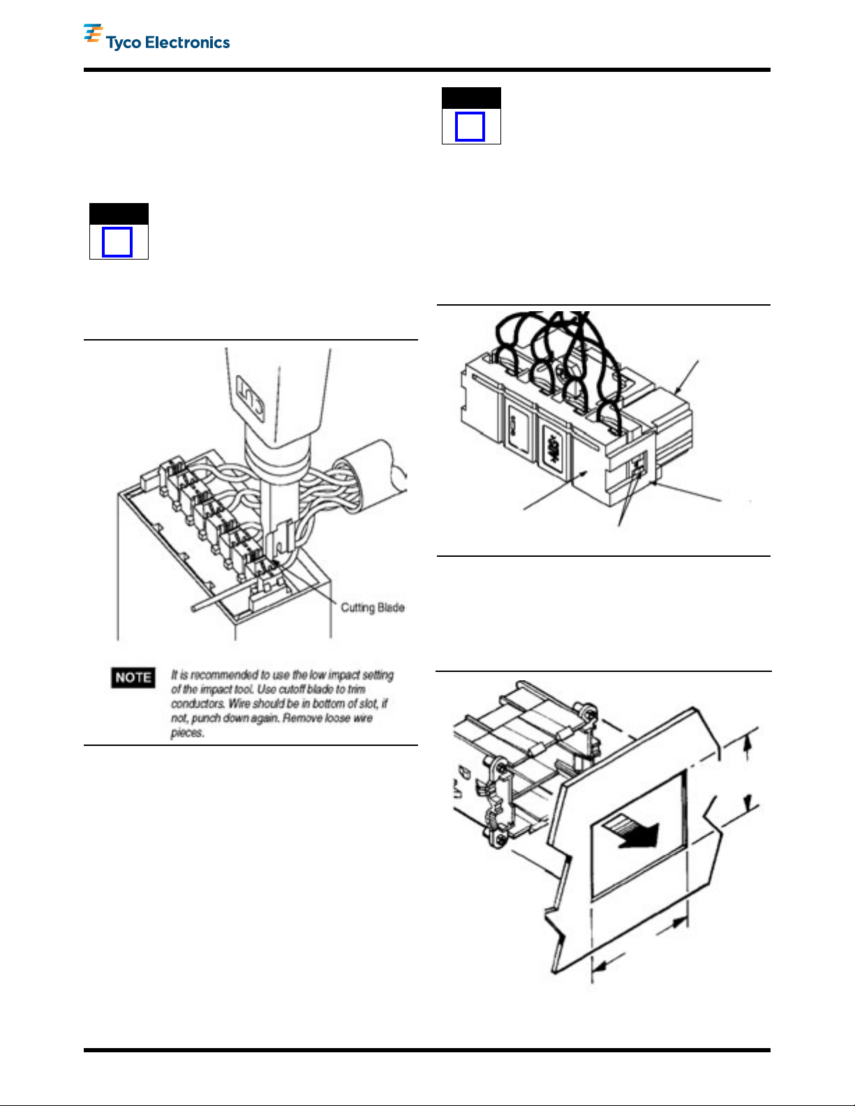
3. Terminate conductors using Impact Tool 558418-1, 569994-1, 346859-1, or 1375308-1. See Figure 3.
It is recommended to maintain the pair twists to
within 6.4 mm [.25 in.] of the termination with
Category 6 cables
5. Terminate conductors using Impact Tool 558418-1, 569994-1, 346859-1, or 1375308-1. See Figure 3.
3. INSTALLING COVER
Mate cover as shown in Figure 4. Make sure latches on cover enter to all pins in the housing. Listen for the double click, which indicates correct connection.
Figure 3
2.2. Shielded Applications
1. Remove approximately 70.0 mm [2.75 in.] of the cable jacket.
2. Remove 60.0 mm [2.36 in.] of the metal foil/braid. Fold the 10.0 mm [.39 in.] metal foil/braid back over the cable jacket as shown in Figure 2.
3. If a drain wire exists, do not remove it. Wrap all of the drain wire around the metal foil/braid.
4. Determine the direction of the cable exit (either left or right). Using the template in Figure 2, arrange pairs accordingly.
Figure 4
4. PANEL MOUNT
4.1. Unshielded Option
1. Snap housing into back of panel.
(Figure 5)
Figure 5
Rev A
2 of 4
Page 3

2. Install two No. 2 screws into two posts located
Screw
Serrated Washer
Housing Post
Existing Panel
Cutout
68.6 [2.70]
(Approx)
35.05 [1.38] (Approx)
228.5 to 457.2
[9 to 18]
Bezel
Adapter
Housing
NOTE
i
NOTE
i
Shield Clip
Guide
Latches
Remove to
Fit Cable
diagonally apart. Tighten screws to clamp housing
to panel. See Figure 6.
Figure 6
4.2. Shielded Option (Grounding Option)
Inserting the housing into a metal panel will ground the housing; however, if an absolute electrical ground is required, proceed as follows:
1. Press the two No. 4 serrated washers onto two diagonal posts of the housing. See Figure 7.
408-8700
Figure 7
2. Snap housing into BACK of panel.
3. Install the two No. 2 screws onto the two posts which hold the serrated washers. Tighten screws to clamp housing to panel. See Figure 6.
5. FURNITURE RACEWAY (Figure 8)
1. Pull cable through panel cutout.
2. Snap housing into BACK of bezel adapter.
3. If using furniture raceway faceplate kits, snap the bezel adapter and housing assembly into the raceway opening.
6. SHIELDED APPLICATIONS
1. Break away a portion of the tab on the side of the metal shield (side oriented with cable exit). See Figure 9.
Figure 8
To minimize electromagnetic interference (EMI),
remove a small portion of the tab at a time to
provide a tight fit around the cable shield.
To ensure optimum performance, be sure to follow
national and local grounding ("earthing"), bonding,
and EMC regulations and procedures.
2. Install shield clip as shown in Figure 9. Shield clip should make contact with metal braid.
Figure 9
Rev A
3 of 4
Page 4

3. Slide the metal shield onto the guides on the
Blank Insert
CAUTION
!
BACK of the housing. Push shield over housing until
all four latches snap into place.
7. INSTALLATION OF INSERTS
1. Install connector inserts by pushing the insert into the appropriate port. Align insert latches with tabs on the edge of the housing. If a port is not used, install a blank insert into the port. See Figure 10.
Figure 10
408-8700
Figure 12
9. BEZEL ADAPTER REMOVAL
Release each corner latch with the blade of a small screwdriver while pulling outward lightly on the bezel adapter. See Figure 13.
2. If installing the faceplate kit, align and press the faceplate onto the FRONT of the housing. See Figure 11.
Figure 11
8. CONNECTOR INSERT REMOVAL
1. Pull the faceplate straight out or pry the faceplate at the slot on each side.
2. Insert a small screwdriver blade into the gap on the side of the insert (between the insert and the tab on the edge of the housing). As each latch disengages, rock the insert to release the side. See Figure 12.
3. Repeat procedure on the other side; then remove insert.
Do NOT try to pry insert out.
Figure 13
10. REVISION SUMMARY
Since the previous release of this instruction sheet, the TE logo has been applied.
Rev A
4 of 4
 Loading...