

Page 1

GPS Receivers A1082-A
A description of Tyco Electronics’
GPS module A1082-A
User’s Manual
Version 1.0
Hardware Revision 01
Page 2

This page was intentionally left blank.
Page 3
Revision History
Revision History
Rev. Date Description
1.0 25-10-07 Initial Draft.
mm-dd-yy
V1.0 - 10/07 User’s Manual Page 3 of 27
Page 4

Disclaimer
Disclaimer
THIS DOCUMENT CONTAINS PROPRIETARY INFORMATION OF TYCO ELECTRONICS CORPORATION/POWER SYSTEMS (TYCO ELECTRONICS). IT MAY
NOT BE COPIED OR TRANSMITTED BY ANY MEANS, PASSED TO OTHERS,
OR STORED IN ANY RETRIEVAL SYSTEM OR MEDIA, WITHOUT PRIOR
CONSENT OF TYCO ELECTRONICS OR ITS AUTHORIZED AGENTS.
THE INFORMATION IN THIS DOCUMENT IS, TO THE BEST OF OUR
KNOWLEDGE, ENTIRELY CORRECT. HOWEVER, TYCO ELECTRONICS CAN
NEITHER ACCEPT LIABILITY FOR ANY INACCURACIES, OR THE
CONSEQUENCES THEREOF, NOR FOR ANY LIABILITY ARISING FROM THE
USE OR APPLICATION OF ANY CIRCUIT, PRODUCT, OR EXAMPLE SHOWN IN
THE DOCUMENT.
THE PRODUCT (HARD- AND SOFTWARE) DESCRIBED IN THIS DOCUMENTATION IS NOT AUTHORIZED FOR USE IN LIFE SUPPORT DEVICES OR
SYSTEMS WITHOUT THE EXPRESS WRITTEN APPROVAL OF TYCO ELECTRONICS.
THIS DOCUMENT MAY PROVIDE LINKS TO OTHER WORLD WIDE WEB SITES
OR RESOURCES. BECAUSE TYCO ELECTRONICS HAS NO CONTROL OVER
SUCH SITES AND RESOURCES, TYCO ELECTRONICS SHALL NOT BE
RESPONSIBLE FOR THE AVAILABILITY OF SUCH EXTERNAL SITES OR
RESOURCES, AND DOES NOT ENDORSE AND IS NOT RESPONSIBLE OR
LIABLE FOR ANY CONTENT, ADVERTISING, PRODUCTS, OR OTHER
MATERIALS ON OR AVAILABLE FROM SUCH SITES OR RESOURCES. TYCO
ELECTRONICS SHALL NOT BE RESPONSIBLE OR LIABLE, DIRECTLY OR
INDIRECTLY, FOR ANY DAMAGE OR LOSS CAUSED OR ALLEGED TO BE
CAUSED BY OR IN CONNECTION WITH USE OF OR RELIANCE ON ANY SUCH
CONTENT, GOODS OR SERVICES AVAILABLE ON OR THROUGH ANY SUCH
SITE OR RESOURCE.
TYCO ELECTRONICS RESERVES THE RIGHT TO CHANGE, MODIFY, OR
IMPROVE THIS DOCUMENT OR THE PRODUCT DESCRIBED HEREIN, AS
SEEN FIT BY TYCO ELECTRONICS WITHOUT FURTHER NOTICE.
Page 4 of 27 User’s Manual V1.0 - 10/07
Page 5

Table of Content
Table of Contents
1 Introduction........................................................................................................7
1.1 Label ................................................................................................................. 7
1.2 Characteristics ..................................................................................................8
1.2.1 GPS Characteristics ................................................................................................... 8
1.2.2 Mechanical Characteristics......................................................................................... 8
1.3 Handling Precautions ........................................................................................8
2 Ordering Information.........................................................................................9
2.1 GPS Receiver A1082-A ....................................................................................9
2.2 Packing ............................................................................................................. 9
2.2.1 Packaging of the A1082-A.......................................................................................... 9
2.3 Additional Equipment ...................................................................................... 10
3 Quick Start........................................................................................................11
3.1 Minimum Configuration ................................................................................... 11
3.2 Antenna........................................................................................................... 13
3.3 Serial Port Settings .........................................................................................13
3.4 Improved TTFF ...............................................................................................13
4 Mechanical Outline ..........................................................................................14
4.1 Details Component Side A1082-A................................................................... 14
4.2 Details Solder Side A1082-A........................................................................... 15
5 Pin-out Information..........................................................................................16
5.1 Layout A1082-A ..............................................................................................16
5.2 Description A1082-A Signals .......................................................................... 16
5.3 General Comments .........................................................................................17
6 Electrical Characteristics................................................................................18
6.1 Operating Conditions ......................................................................................18
6.2 Typical Operating Conditions .......................................................................... 18
6.3 Absolute maximum ratings.............................................................................. 19
7 Mounting...........................................................................................................20
7.1 Proposed Footprint for Soldering ....................................................................20
7.2 Recommended Profile for Reflow Soldering ...................................................20
8 Use of Antenna.................................................................................................21
8.1 Connection of RF Signal ................................................................................. 21
9 Quality and Reliability......................................................................................22
9.1 Environmental Conditions ............................................................................... 22
9.2 Product Qualification .......................................................................................22
9.3 Production Test ............................................................................................... 22
Demonstration Kits.............................................................................................23
9.4 Evaluation Kit A1082-A ................................................................................... 23
10 Application and Hints....................................................................................24
V1.0 - 10/07 User’s Manual Page 5 of 27
Page 6

Table of content
Page 6 of 27 User’s Manual V1.0 - 10/07
10.1 Enable PIN (P1.6) ......................................................................................... 24
10.2 1PPS PIN...................................................................................................... 24
10.3 Standby PIN (P1.5) ....................................................................................... 24
10.4 FDOUT PIN................................................................................................... 24
11 Related Information .......................................................................................25
11.1 Contact.......................................................................................................... 25
11.2 Related Documents....................................................................................... 25
12 List of Tables..................................................................................................27
13 List of Figures ................................................................................................27
Page 7
GPS receiver A1082-A
1 Introduction
Tyco Electronics’ GPS module A1082-A is a highly integrated GPS receiver module
that can be used as an SMT component. It is capable to receive signals from up to
12 GPS satellites and transferring them into position and timing information that can
be read over a serial port. This new generation of GPS module combines small size
and high-end GPS functionality at lowest power consumption:
• Operable at 1.8V / 65mW (typ.) @ trickle power mode
• Small form factor of 13.97 x 11.43 mm (0.55” x 0.45”)
• Cost-effective antenna input
• Single-sided SMD-BGA component, for reflow soldering
• Tape & reel packaging
The A1082-A GPS receivers are available as off-the-shelf component, 100% tested
and shipped in standard tape-and-reel package.
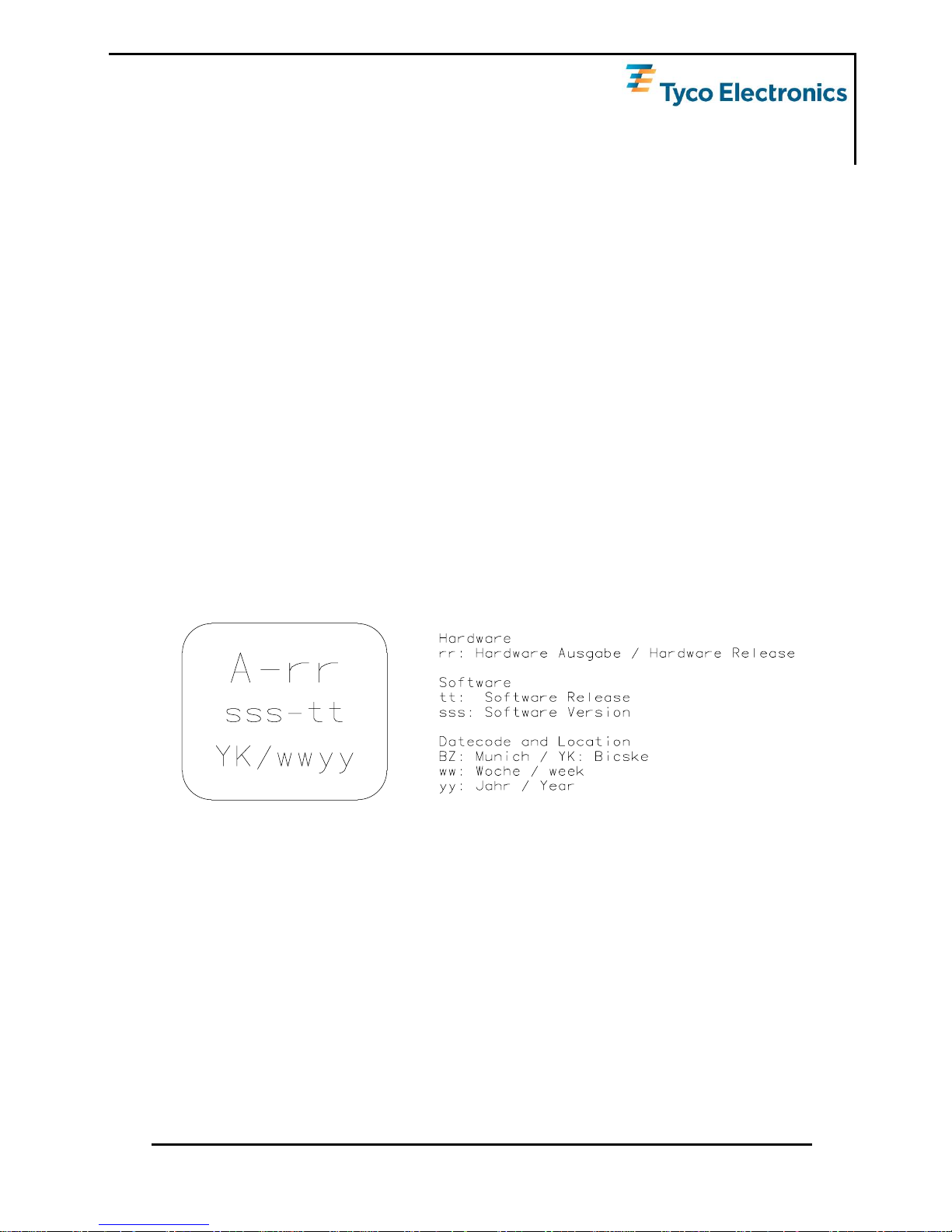
1.1 Label
The A1082-A label holds the following information:
Figure 1: A1082-A label
V1.0 - 10/07 User’s Manual Page 7 of 27
Page 8
GPS receiver A1082-A
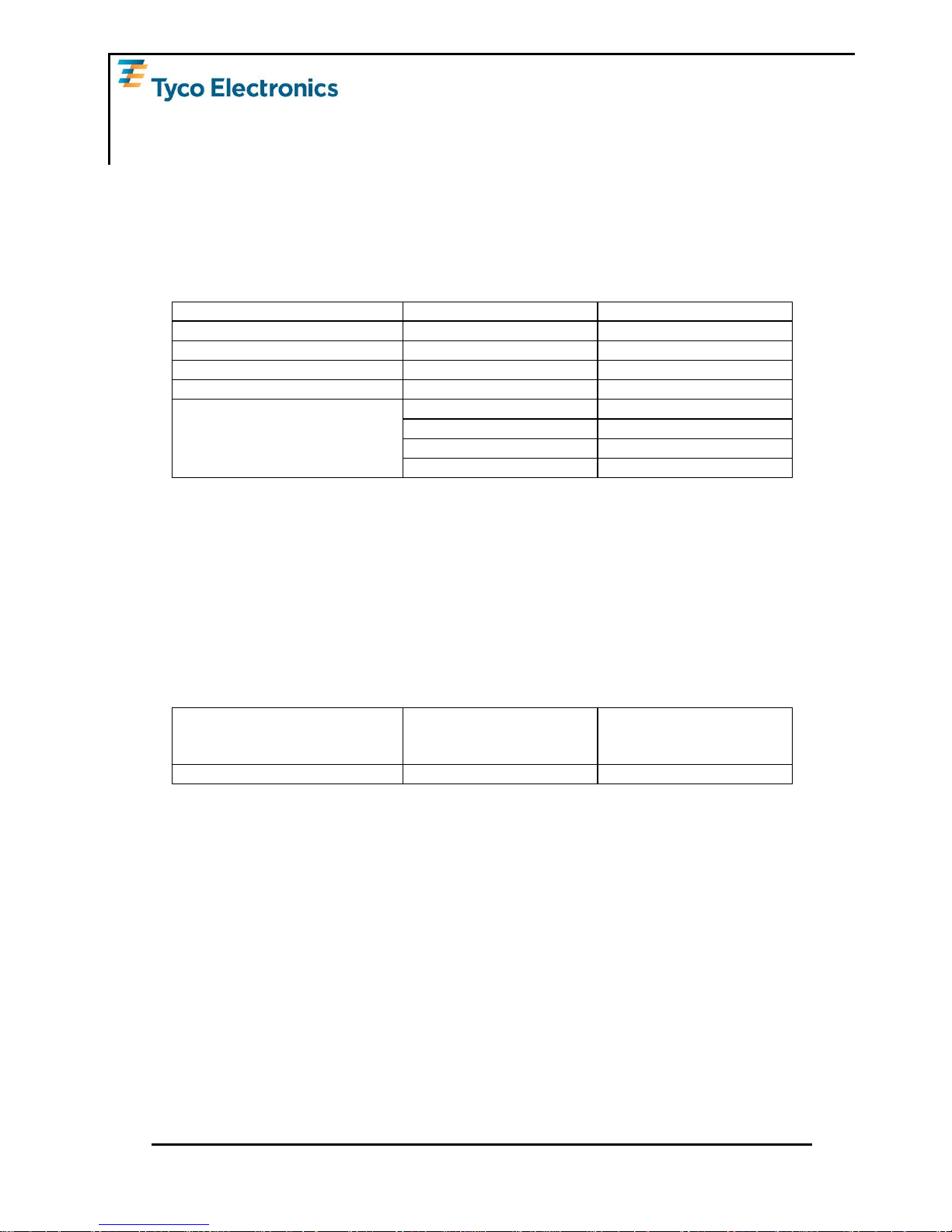
1.2 Characteristics
The modules are characterized by the following parameters.
1.2.1 GPS Characteristics
Channels 12, parallel tracking
Correlators 20.000
Frequency L1 (= 1575 MHz)
Tracking Sensitivity -157dBm
Horizontal Position Accuracy Stand alone
(5)
< 2,5m CEP (SA off)
Obscuration recovery
(1)
0.1s
Hot start
(2)
< 1s
Warm
(3)
< 35s
Time To First Fix – TTFF
(theoretical minimum values;
values in real world may differ)
Cold
(4)
< 37s
Table 1: A1082 GPS characteristics
(1) The calibrated clock of the receiver has not stopped, thus it knows precise time (to the µs level).
(2) The receiver has estimates of time/date/position and valid almanac and ephemeris data.
(3) The receiver has estimates of time/date/position and recent almanac.
(4) The receiver has no estimate of time/date/position, and no recent almanac.
(5) CEP 50% 24 hours static
1.2.2 Mechanical Characteristics
A1082-A Mechanical dimensions
Length
Width
Height
13.97mm, 0.55”
11.43mm, 0.45”
2.4mm, 0.095”
A1082-A Weight 1g, < 0.05oz
Table 2: A1082-A dimensions and weight
1.3 Handling Precautions
The GPS receiver module A1082-A is sensitive to electrostatic discharge (ESD).
Please handle with appropriate care.
Page 8 of 27 User’s Manual V1.0 - 10/07
Page 9
GPS receiver A1082-A
2 Ordering Information
2.1 GPS Receiver A1082-A
The order number is built as follows:
• V23993A1082A
V23993 stands for Tyco Electronics wireless and communication products, A1082A
for the A1082-A module.
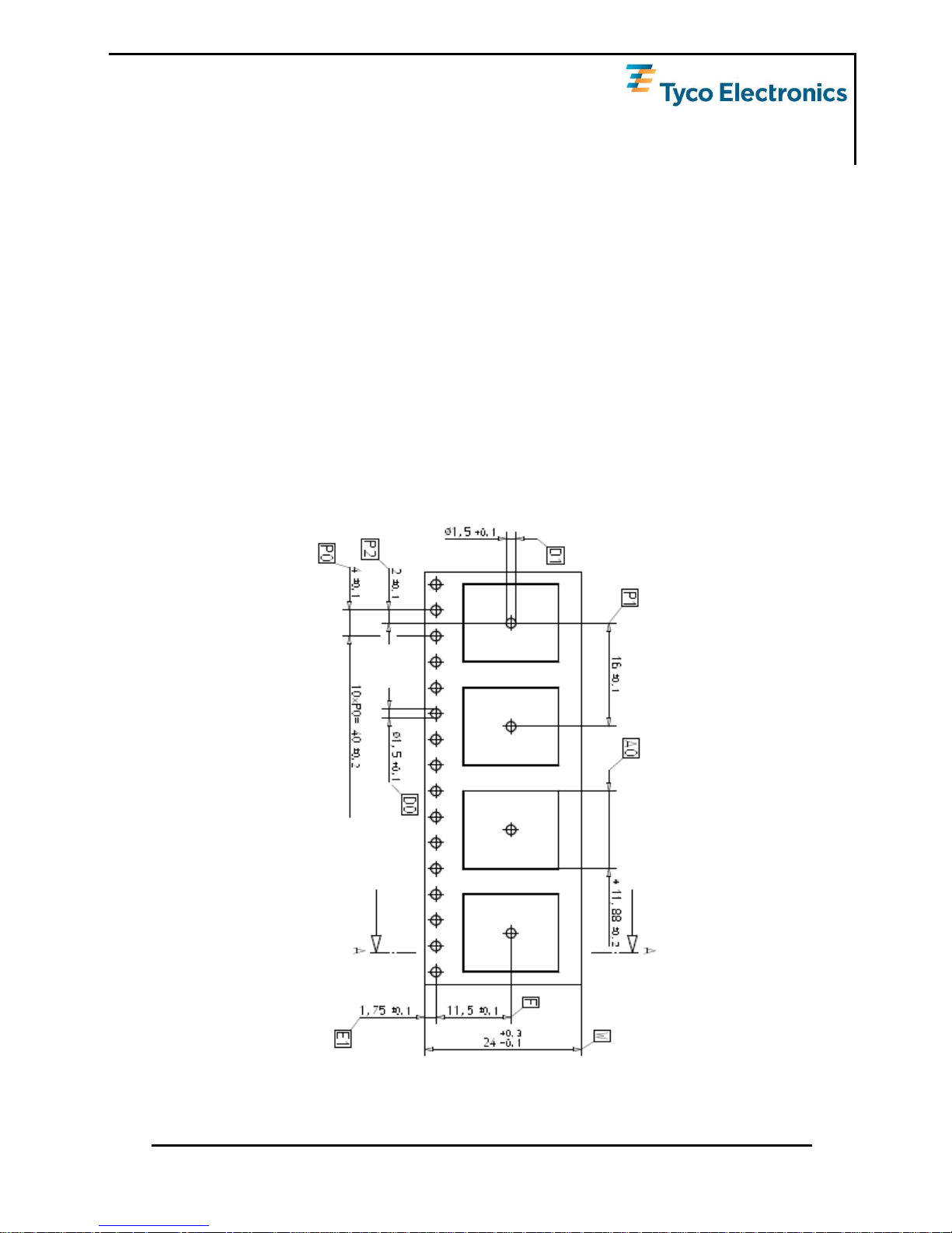
2.2 Packing
2.2.1 Packaging of the A1082-A
The A1080-A GPS module comes in a tape and reel package suitable for pick and
place machines.
Figure 2: A1082-A tape specifications (1)
V1.0 - 10/07 User’s Manual Page 9 of 27
Page 10

GPS receiver A1082-A
Figure 3: A1082-A tape specifications (2)
2.3 Additional Equipment
V23993EVA1082A Evaluation Kit (including one module V23993A1082A)
Table 3: Additional equipment
A detailed description of the additional kit can be found in the according manuals.
Page 10 of 27 User’s Manual V1.0 - 10/07
Page 11

GPS receiver A1082-A
3 Quick Start
In order to allow an easy and quick start with the modules A1082-A, this chapter
provides a short overview on the most important steps to receive NMEA messages
with position information on a serial port.
3.1 Minimum Configuration
The following picture shows a recommended minimum configuration for NMEA output and commands sent and received via an RS232 interface based on the GPS
module A1082-A.
V1.0 - 10/07 User’s Manual Page 11 of 27
Page 12

GPS receiver A1082-A
Figure 4: Recommended minimum configuration A1082-A
Page 12 of 27 User’s Manual V1.0 - 10/07
Page 13

GPS receiver A1082-A
3.2 Antenna
The A1082-A GPS module is optimized for active antennas.
3.3 Serial Port Settings
The default configuration within the standard GPS firmware is:
• Serial 0 (NMEA) 4,800 baud, 8 data bits, no parity, 1 stop bit, no flow control
3.4 Improved TTFF
In order to improve the TTFF (Time To First Fix), it is recommend to keep the Vcc &
VCC_CPU all the time and use Enable PIN (see chapter 10.1 Enable Pin) or software standby function.
Please see Firmware User manual for details.
V1.0 - 10/07 User’s Manual Page 13 of 27
Page 14

GPS receiver A1082-A
4 Mechanical Outline
4.1 Details Component Side A1082-A
All dimensions in [mm, (inch)]
Figure 5: Mechanical outline component side A1082-A
Page 14 of 27 User’s Manual V1.0 - 10/07
Page 15

GPS receiver A1082-A
4.2 Details Solder Side A1082-A
1.271.27
1.27
1.27
1.27
1.27
1.27
1.27
0.60
PIN1
PIN2
PIN3
PIN4
PIN5
PIN6
PIN7
PIN8
PIN16
PIN15
PIN14
PIN13
PIN12
PIN11
PIN10
PIN9
Solder pad size: Ø 0.6mm
All dimensions in [mm]
Figure 6: Mechanical outline solder side A1082-A
V1.0 - 10/07 User’s Manual Page 15 of 27
Page 16

GPS receiver A1082-A
5 Pin-out Information
5.1 Layout A1082-A
Figure 7: Pin-out information A1082-A
5.2 Description A1082-A Signals
PIN Name Function Comment
1 1PPS Output 1 Pulse Per Second
2 TX0 Output NMEA 4800 baud output
3 RX0 Input NMEA 4800 baud input
4 Reserved Input Reserved (leave open)
5 FDOUT Output Low power (trickle, standby) indicator
6 GND_ANT RF GND Antenna Ground, do not connect to GROUND,
connect to antenna shield
7 RF_IN Input RF input (Antenna input , Z=50 Ohm)
8 GND_ANT RF GND Antenna Ground, do not connect to GROUND,
connect to antenna shield
9 Reserved Input/Output Reset (leave open)
10 Reserved Input Reserved (leave open)
11 P1.6 Input Enable (low active)
12 P1.5 Input Standby (high active)
13 Reserved Input SBWTCK (do not connect)
14 VCC_CPU Power Vcc 1.8V (+/- 5%)
15 VCC Power Vcc 1.8V (+/- 5%)
16 GND GND Ground
PIN1
PIN2
PIN3
PIN4
PIN5
PIN6
PIN7
PIN8
PIN16
PIN15
PIN14
PIN13
PIN12
PIN11
PIN10
PIN9
Table 4: Pin description A1082-A
Page 16 of 27 User’s Manual V1.0 - 10/07
Page 17

GPS receiver A1082-A
5.3 General Comments
The following comments should be considered for a design with and use of the
module:
• Standard configuration of serial port (standard GPS software):
Serial 0 (NMEA) 4,800 baud, 8 data bits, no parity, 1 stop bit, no flow control
• Antenna (Antenna connected to Antenna Pin)
Use ground pins (PIN6, PIN8) close to the antenna input for RF ground.
V1.0 - 10/07 User’s Manual Page 17 of 27
Page 18

GPS receiver A1082-A
6 Electrical Characteristics
6.1 Operating Conditions
Pin Description Min Typical Max
V
cc
1.75V 1.8V 1.85V
Peak Acquisition Current
(1)
110mA 120mA
Tracking Current
(2)
50mA 60mA
Tracking Current, trickle mode
(3)
35mA 50mA
7
Standby Current
(4)
30 µA
Table 5: A1082 electrical characteristics
(1) Peak acquisition current is characterized by millisecond bursts above average acquisition cur-
rent
(2) Tracking current typically includes tracking and the post acquisition portion of TTFF
(3) Tracking current with activated trickle power mode (standard configuration)
(4) During standby state: RTC block and core powered on and clock off.
6.2 Typical Operating Conditions
1
2
3
4
5
Figure 8: typical operating condition A1082-A
Page 18 of 27 User’s Manual V1.0 - 10/07
Page 19

GPS receiver A1082-A
Acquiring first satellite (cold start only)
1
Acquiring all satellites which are necessary to calculate a fix (cold start only)
2
Ephemeris download from all visible satellites
3
Trickle power mode
4
Hot start after resetting the module
5
6.3 Absolute maximum ratings
Symbol Parameter Min Max Unit
V
CC
Power Supply GSCi500x -0.3 +1.85 V
V
CC_CPU
Power Supply host processor -0.3 +1.85 V
V
in
Voltage to any input pin -0.3 +2.0 V
I
out
Input current on any pin -10 +10 mA
I
tdv
Absolute sum of all input currents during overload condition 200 mA
Table 6: Absolute maximum ratings
Stresses beyond those listed under “Absolute Maximum Ratings” may cause permanent damage to the device. This is a stress rating only. Functional operation of
the device at these or any other conditions beyond those indicated in the operational sections of this specification is not implied. Exposure to absolute maximum
rating conditions for extended periods may affect device reliability.
V1.0 - 10/07 User’s Manual Page 19 of 27
Page 20

GPS receiver A1082-A
7 Mounting
This chapter covers the mounting of the A1082-A.
7.1 Proposed Footprint for Soldering
The following proposal of a footprint for soldering is assuming a stencil thickness of
150µm. ³ marks the center of the through holes.
TBD
Figure 9: Soldering footprint proposal A1082-A
Please note that copper and solder paste footprint are identical. The final footprint
has to be evaluated and qualified by the manufacturer according to the specific
processes.
7.2 Recommended Profile for Reflow Soldering
Typical values for reflow soldering of the module in convection or IR/convection ovens are as follows:
Peak temperature (RoHS compliant process)
245°C
Average ramp up rate to Peak (183°C to Peak) 3°C / second max.
Preheat temperature 125 (±25°C)
120 seconds max.
Temperature maintained above 183°C
60 … 150 seconds
Time within 5°C of actual peak temperature
10 … 20 seconds
Ramp Down rate
6°C / second max.
Time 25°C to peak temperature
6 minutes max.
Table 7: Reflow soldering profile A1082-A
As results of soldering may vary among different soldering systems and types of
solder and depend on additional factors like density and types of components on
board, the values above should be considered as a starting point for further optimization.
Page 20 of 27 User’s Manual V1.0 - 10/07
Page 21

GPS receiver A1082-A
8 Use of Antenna
8.1 Connection of RF Signal
The ANT pin is used to connect the receiver with the GPS antenna. The design of
the antenna connection has to be done strictly according to RF design rules. A 50Ω
PCB strip line is required. The following drawings shall explain the guidelines. A
major rule is to keep the strip line as short as possible. Additionally, antenna ground
(GNDANT) should be routed to the ground plane of the PCB (the ground plane is
on a lower PCB layer) by via as demonstrated in the drawing.
Motherboard GND layer Motherboard top layer
GPS module
RF
in
RF
GND
RF
GND
GPS module
RF
in
RF
GND
RF
GND
Figure 10: Antenna connector strip line A1082-A
In order to gain the impedance of 50Ω, the width of the strip line needs to be calculated. It depends on the thickness or height of the PCB layer (both parameters are
shown in following drawing). For the calculation, it is assumed that the PCB material is FR4.
Figure 81: Strip line parameters A1082-A
In this case, the width should be about 1.8 times the height of the PCB:
W = 1.8 x H
In the example, one would get a width of W = 1.8 x 0.8mm = 1.44mm.
50Ωstrip line
Vias to Top Layer
Vias to GND Layer
BGA Solder pads
V1.0 - 10/07 User’s Manual Page 21 of 27
Page 22

GPS receiver A1082-A
9 Quality and Reliability
9.1 Environmental Conditions
Operating temperature
-40 … +85°C
Operating humidity
Max. 85% r. H., non-condensing, at 85°C
MSL JEDEC
(Moisture Sensitivity Level)
3
Storage 6 months in original package.
Table 8: Environmental conditions
9.2 Product Qualification
Prior to product qualification the GPS receiver is preconditioned according to
EIA/JEDEC standard JESD22-A113-B / Level 3.
Basic qualification tests:
• MSL Classification according to J-STD-020C (MSL3 @ 245°C)
• MSL Rework Compatibility according to J-STD-020C
• Temperature Cycling –40°C … +85°C
• Temperature Humidity Bias 70°C / 85% RH
• High / Low Temperature Operating –40° / +85°C
• High Temperature Operating Life +85°C
• Vibration Variable Frequency
• Mechanical Shock
Please contact Tyco Electronics for detailed information.
9.3 Production Test
Each module is electrically tested prior to packing and shipping to ensure state of
the art GPS receiver performance and accuracy.
Page 22 of 27 User’s Manual V1.0 - 10/07
Page 23

GPS receiver A1082-A
Demonstration Kits
9.4 Evaluation Kit A1082-A
For demonstration and easy evaluation of GPS performance Tyco Electronics offers
a Demonstration Kit (including one GPS A1082-A module). It contains a USB interface with according drivers to connect easily to a PC. The USB interface is an extension of the serial port 0, therefore sending NMEA sentences and accepting
commands. At the same time it provides power to the module. Accompanied by an
antenna it offers a ready-to-go set.
For the development of new software and applications the Evaluation Kit also provides NMEA messages on C-MOS level via a terminal plug.
For further information please contact Tyco Electronics.
V1.0 - 10/07 User’s Manual Page 23 of 27
Page 24

GPS receiver A1082-A
10 Application and Hints
10.1 Enable PIN (P1.6)
The Enable PIN is an input PIN and low active.
The module will immediately switch to standby mode by pulling the Enable PIN to
“low”. The RTC keeps running and the internal SRAM will be back upped. This
keeps the Ephemeris and Almanac stored. Pulling the Enable PIN back to “high”
within 2 hours will end in hot start situation.
10.2 1PPS PIN
The 1PPS pin is an output pin.
In addition to precise positioning, GPS also allows for accurate timing due to the
synchronized atomic clocks in the GPS satellites. While the current date and time is
transmitted in NMEA sentences, an exact and accurate timing signal is provided via
the 1PPS pin of the A1082-A modules.
10.3 Standby PIN (P1.5)
The Standby pin is an input pin and high active.
Pulling Standby pin to high will activate trickle power mode with factory preset variables. Please see Firmware manual A1082-A.
10.4 FDOUT PIN
FDOUT Pin is an output pin.
FDOUT indicates active low power modes (trickle, standby). Typical application to use this
pin is to deactivate external LNA or active antenna to reduce power consumption to minimum.
Page 24 of 27 User’s Manual V1.0 - 10/07
Page 25

GPS receiver A1082-A
11 Related Information
11.1 Contact
This manual was created with due diligence. We hope that it will be helpful to the
user to get the most out of the GPS module.
Anyway, inputs about errors or mistakable verbalizations and comments or proposals to TYCO Electronics, Power Systems in Munich, Germany, for further improvements are highly appreciated.
Tyco Electronics
Power Systems
Finsinger Feld 1
85521 Ottobrunn, Germany
Tel.: +49 89 6089 838
Fax: +49 89 6089 835
mailto:gps@tycoelectronics.com.
http://www.tycoelectronics.com/gps.
Further contact addresses:
Info.mailto:gps@tycoelectronics.com.
support.mailto:gps@tycoelectronics.com.
sales.mailto:gps@tycoelectronics.com.
11.2 Related Documents
• Manual: Instant GPS IC Interface Control Drawing manual (SiRF)
V1.0 - 10/07 User’s Manual Page 25 of 27
Page 26

GPS receiver A1082-A
Page 26 of 27 User’s Manual V1.0 - 10/07
This page was intentionally left blank.
Page 27

List of tables and figures
12 List of Tables
Table 1: A1082 GPS characteristics ........................................................................ 8
Table 2: A1082-A dimensions and weight................................................................ 8
Table 3: Additional equipment................................................................................ 10
Table 4: Pin description A1082-A........................................................................... 16
Table 5: A1082 electrical characteristics................................................................ 18
Table 6: Absolute maximum ratings....................................................................... 19
Table 7: Reflow soldering profile A1082-A ............................................................. 20
Table 8: Environmental conditions ......................................................................... 22
13 List of Figures
Figure 1: A1082-A label ........................................................................................... 7
Figure 2: A1082-A tape specifications (1) ................................................................ 9
Figure 3: A1082-A tape specifications (2) .............................................................. 10
Figure 4: Recommended minimum configuration A1082-A.................................... 12
Figure 5: Mechanical outline component side A1082-A ......................................... 14
Figure 6: Mechanical outline solder side A1082-A ................................................. 15
Figure 7: Pin-out information A1082-A ................................................................... 16
Figure 8: typical operating condition A1082-A........................................................ 18
Figure 9: Soldering footprint proposal A1082-A ..................................................... 20
Figure 10: Antenna connector strip line A1082-A................................................... 21
Figure 81: Strip line parameters A1082-A .............................................................. 21
V1.0 - 10/07 User’s Manual Page 27 of 27
 Loading...