

Page 1
Instruction Sheet
1.02--2.0
3
Blueand
Y
1.52--2.5
4
Whi
t
d
2.03--2.9
2
408--1538
25 AUG 10 Rev LHand Crimping Tools 90015 and 90016
PROPER USE GUIDELINES
Cumulative Trauma Disorders can resultfromthe prolonged useof manually powered hand tools. Hand tools areintended for occasional useand low volume
applications. A wide selection of powered application equipment for extended--use, production operations is available.
Tool Part
Back Side
of Tool
Color Code
Marking
Wire Size
Marking (Ref)
Number (Ref)
Terminal
Locator
Crimping
Jaws
SIZE
(AWG)
26
24--22
26
20--18
16
CERTI--CRIMP*
Tool Ratchet
Insulation Crimping
Adjustment Pins
WIRE TERMINAL HAND TOOL
INSULATION
DIA (mm [in.])
1.02--2.03
[.040--.080]
2.03--2.92
[.080--.115]
1.52--2.54
[.060--.100]
2.03--2.92
[.080--.115]
STRIP LENGTH
(mm [in.])
3.96 [.156]
4.75 [.187]
BASE PART
NUMBER
42927 Short
66059 Long
42574 Short
42633 Long
66129 Long Black
42575 Short
42634 Long
42637 Short
42646 Long
SHOULDER
LENGTH
SLEEVE
COLOR
Blue
ellow
White
Black
PART
NUMBER
90015
90016
COLOR
CODE
Blue and
Yellow
ean
Black
CRIMP DOT
CODE
1
2
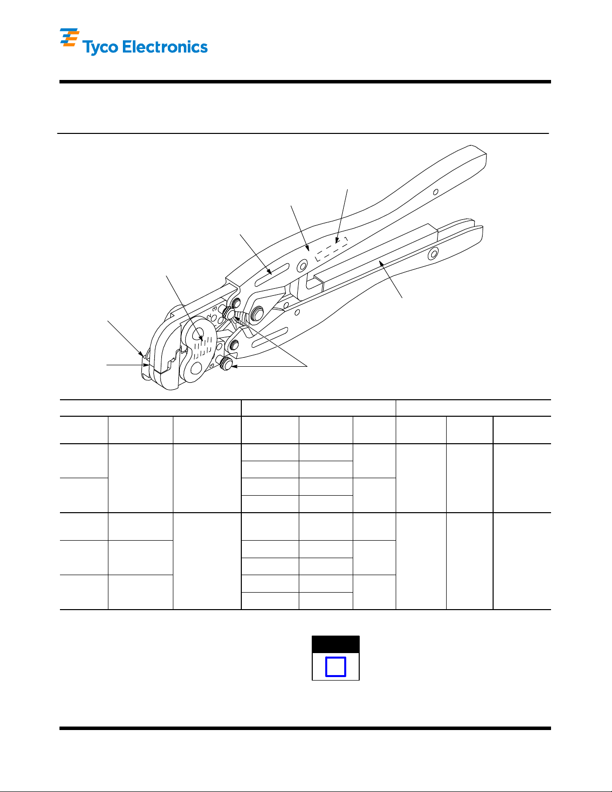
Figure 1
1. INTRODUCTION
NOTE
Dimensions in this instruction sheet are in metric
units [with U.S. customary units in brackets].
Hand Crimping Tools 90015 and 90016 crimp the
i
PIDG* taper pin terminals (listed in Figure 1) onto
wire sizes 26 through 16 A WG. Read these
instructions thoroughly before crimping any terminals.
E2010 Tyco Electronics Corporation, Berwyn, PA
All Rights Reserved
TE logo and Tyco Electronics ar e trademarks.
*Trademark. Other product names, logos, or company names might be trademarks of their respective owners.
TOOLING ASSISTANCE CENTER 1--800--722--1111
PRODUCT INFORMATION 1--800--522--6752
Reasons for reissue of this instruction sheet are
provided in Section 7, REVISION SUMMARY.
This controlled document is subject to change.
For latest revision and Regional Customer Service,
visit our website at www.tycoelectronics.com
1 of 5
LOC B
Page 2
Hand Crimping Tools 90015 and 90016
408- 1538
2. DESCRIPTION
Each hand tool features two crimping jaws, a terminal
locator, two insulation crimping adjustment pins, and
a CERTI--CRIMP tool ratchet. The hand tool has the
tool part number , color code, and wire size marked on
the BACK side of the tool. The color code must match
the color of the terminal sleeve. The terminal locator
positions the terminal between the crimping jaws and
is adjustable to accommodate long or short shoulder
terminals. The insulation crimping adjustment pins are
used to regulate the crimp height of the insulation
barrel sleeve.
The ratchet assures full crimping of the terminal.
Once engaged, the ratchet will not release until the
tool handles have been FULL Y closed. See Figure 1.
CAUTION
!
The crimping jaws bottom before the
CERTI--CRIMP tool ratchet releases. This design
feature ensures maximum electrical and tensile
performance of the crimp. Do NOT re--adjust the
ratchet.
3. CRIMPING PROCEDURE
NOTE
i
Refer to Figure 1 and select the appropriate wire size
and terminal for the hand tool. The wire size and
insulation diameter must be within the specified range
for the terminal and hand tool.
The tool is coated with a preservative to prevent
rust or corrosion. Wipe this preservative from the
tool, particularly from the crimping jaws, before
using the tool.
1. Strip the wire using the appropriate strip--length
dimension provided in Figure 1. Do NOT nick or
cut the wire strands.
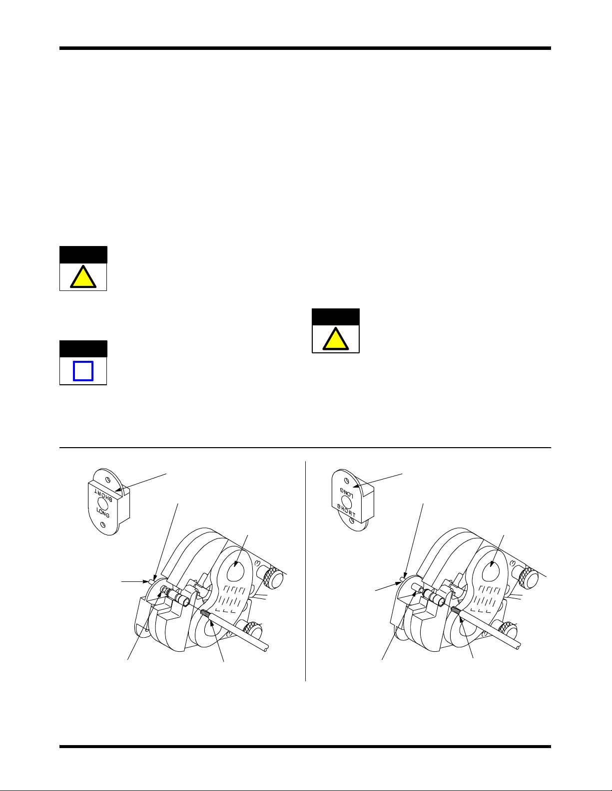
2. Adjust the terminal locator to accommodate the
shoulder length of the terminal being crimped. See
Figure 2.
3. Hold tool so that the BACK side of the tool is
facing you.
4. Open the crimping jaws by squeezing the tool
handles together until the CERTI--CRIMP ratchet
releases.
5. Insert the tip of the terminal through the hole in
the locator. The shoulder of the terminal must be
positioned against the locator as shown in
Figure 2.
6. Hold terminal in position and squeeze the tool
handles together just enough to hold the terminal in
the crimping jaws.
CAUTION
!
7. Insert stripped wire through the insulation barrel
sleeve and into the wire barrel sleeve until it
bottoms. See Figure 2.
8. Hold wire in place and squeeze tool handles
together until the CERTI--CRIMP ratchet releases.
Allow tool handles to open FULLY.
Squeezing the handles together too much will
engage the crimping jaws and deform the
terminal.
Tip of Terminal
Inserted Through
Hole in Locator
Shoulder of Short Shoulder
Terminal Against Locator
Terminal Locator
Adjusted for Short
Shoulder Terminals
Stripped
Wire
Back Side
of Tool
Figure 2
Tip of Terminal
Inserted Through
Hole in Locator
Shoulder of Long Shoulder
Terminal Against Locator
Terminal Locator
Adjusted for Long
Shoulder Terminals
Back Side
of Tool
Stripped
Wire
Rev L2 of 5 Tyco Electronics Corporation
Page 3

Hand Crimping Tools 90015 and 90016
408- 1538
Properly Crimped Terminals
Short Shoulder
T erminal
Blue Color
Coded Sleeve
Wire Barrel
Sleeve
9. Remove the crimped terminal from the crimping
jaws and inspect the crimp. The crimp dot code on
the color coded sleeve will identify the hand tool
used. Make sure that the proper crimp dot code is
shown for the appropriate hand tool. Refer to
Figure 1. Refer to Figure 3 for a properly crimped
terminal. Check the insulation grip by referring to
Section 4, INSULA TION CRIMPING
ADJUSTMENT.
CAUTION
Discard and replace any defective or damaged
terminal. DO NOT re--use a crimped terminal.
Crimp Dot
Code (1 Dot)
0.794 mm [.031 in.]
!
4. INSULATION CRIMPING ADJUSTMENT
Each hand tool has three insulation crimping
adjustment positions to adjust the wire insulation grip:
1--Tight, 2--Medium, and 3--Loose. To obtain the
desired insulation grip, proceed as follows:
1. Insert insulation crimping adjustment pins into
Position3asshowninFigure1.
2. Position terminal into crimping jaws as
described in Section 3, Step 5.
3. Insert an UNSTRIPPED wire just into the
insulation barrel sleeve.
4. Crimp the terminal using the procedure
described in Section 3, Step 8. Remove the
crimped terminal from the crimping jaws and check
the insulation support by bending the wire back
and forth once. The insulation barrel sleeve should
retain grip on the wire insulation. If the wire pulls
out, move the insulation crimping adjustment pins
to the next tighter position (Position 2) and proceed
to Step 5. If the wire does not pull out, the pins are
properly adjusted and the tool is ready for
crimping.
5. Perform another test crimp as described above.
Adjust pins, as necessary , until the desired
Long Shoulder
T erminal
Insulation
Barrel Sleeve
Figure 3
Black Color
Coded Sleeve
insulation grip is obtained. DO NOT use a tighter
setting than is required.
NOTE
The pins must be located in the same adjustment
position.
Crimp Dot
Code (2 Dots)
3.18 mm [.125 in.]
i
5. MAINTENANCE AND INSPECTION PROCEDURE
It is recommended that a maintenance and inspection
program be performed periodically to ensure
dependable and uniform terminations. Frequency of
inspection depends on:
1. The care, amount of use, and handling of the
hand tool.
2. The presence of abnormal amounts of dust and
dirt.
3. The degree of operator skill.
4. Your own established standards.
The hand tool is inspected before being shipped from
the plant; however, Tyco Electronics recommends
that the tool be inspected immediately upon arrival to
ensure that the tool has not been damaged during
shipment.
5.1. Daily Maintenance
1. Hand tool should be immersed (handles partially
closed) in a reliable commercial degreasing
compound to remove accumulated dirt, grease,
and foreign matter. When degreasing compound is
not available, tool may be wiped clean with a soft,
lint--free cloth. DO NOT use hard or abrasive
objects that could damage the tool.
2. Make certain that the retaining pins are in place
and that they are secured with retaining rings.
3. All pins, pivot points, and bearing surfaces
should be protected with a thin coat of any good
SAE 20 motor oil. Do not oil excessively.
3 of 5Rev L Tyco Electronics Corporation
Page 4

Hand Crimping Tools 90015 and 90016
408- 1538
4. When the tool is not in use, keep handles closed
to prevent objects from becoming lodged in the
crimping jaws. Store the tool in a clean, dry area.
5.2. Lubrication
Lubricate all pins, pivot points, and bearing surfaces
with SAE 20 motor oil as follows:
Tools used in daily production—lubricate daily
Tools used daily (occasional)—lubricate weekly
Tools used weekly—lubricate monthly
Wipe excess oil from tool, particularly from crimping
area. Oil transferred from the crimping area onto
certain terminations may affect the electrical
characteristics of an application.
5.3. Visual Inspection
1. Close tool handles until ratchet releases and
then allow them to open freely . If they do not open
quickly and fully, the spring is defective and must
be replaced.
2. Inspect head assembly for worn, cracked, or
broken jaws. If damage is evident, return the tool
to Tyco Electronics for evaluation and repair. See
Section 6, REPLACEMENT AND REPAIR.
5.4. Gaging the Crimping Chamber
This inspection requires the use of plug gages
conforming to the dimensions provided in Figure 4.
Tyco Electronics does not manufacture or market
these gages. To gage the crimping chamber, proceed
as follows:
1. Remove traces of oil or dirt from the crimping
chamber and plug gages.
2. Close the tool handles until it is evident that the
jaws have bottomed; then hold in this position. Do
NOT force the jaws beyond initial contact.
3. Align the GO element with the appropriate
section of the crimping chamber. Push element
straight into the crimping chamber without using
force. The GO element must pass completely
through the crimping chamber as shown in
Figure 4.
evaluation and repair. Refer to Section 6,
REPLACEMENT AND REPAIR.
For additional information regarding the use of plug
gages, refer to instruction sheet 408--7424.
Suggested Plug Gage Design for
Wire Barrel Section of Crimping Chamber
GO
Dim.
NO--GO
Dim.
Jaw Closure
Configuration
HAND TOOL
90015
90016
GAGE ELEMENT DIMENSIONS (mm [in.])
GO NO--GO
1.600--1.607
[.0630--.0633]
2.160--2.167
[.0850--.0853]
1.747--1.750
[.0688--.0690]
2.287--2.290
[.0900--.0902]
Suggested Plug Gage Design for
Insulation Barrel Section of Crimping Chamber
(Gage to be used at position 1 of insulation adjustment)
GO Dim. NO--GO Dim.
GO
NO
GO
“W”
6.35 mm [.250 in.]
Min Typ
Jaw Closure
Configuration
GAGE ELEMENT DIMENSIONS (mm [in.])
HAND TOOL
90015
90016
GO NO--GO
0.889--0.897
[.0350--.0353]
1.394--1.397
[.0549--.0550]
“W” (Width)
(Max)
2.36
[.093]
“W”
4. Align the NO--GO element and try to insert it
straight into the same section of the crimping
chamber. The NO--GO element may start entry,
but must not pass completely through the crimping
chamber. See Figure 4.
If the crimping chamber conforms to the gage
inspection, the crimping chamber is considered
dimensionally correct, and should be lubricated with a
THIN coat of any good SAE 20 motor oil. If not, the
tool must be returned to Tyco Electronics for further
GO
Element
Crimping
Chamber
NO--GO
Element
Figure 4
Rev L4 of 5 Tyco Electronics Corporation
Page 5

Hand Crimping Tools 90015 and 90016
408- 1538
5.5. CERTI- CRIMP Ratchet Inspection
The CERTI--CRIMP ratchet feature on the hand tools
should be checked to ensure that the ratchet does not
release prematurely, allowing the jaws to open before
they have fully bottomed. Obtain a 0.025--mm
[.001--in.] shim that is suitable for checking the
clearance between the bottoming surfaces of the
crimping jaws. Proceed as follows:
1. Select the maximum size wire for the tool and a
terminal.
2. Position the terminal and wire between the
crimping jaws, as described in Section 3,
CRIMPING PROCEDURE.
3. Hold the wire in place and squeeze the handles
until the CERTI--CRIMP ratchet releases. Hold the
handles in this position, maintaining just enough
tension to keep the jaws closed.
4. Check the clearance between the bottoming
surfaces of the crimping jaws. If the clearance is
0.025--mm [.001--in.] or less, the ratchet is
satisfactory. If clearance exceeds 0.025--mm
[.001--in.], the ratchet is out of adjustment and
must be repaired. See Section 6, REPLACEMENT
AND REPAIR.
6. REPLACEMENT AND REPAIR
Replaceable parts are listed in Figure 5. Parts other
than those listed in Figure 5 should be replaced by
Tyco Electronics to ensure quality and reliability of the
tool. Order replacement parts through your Tyco
Electronics representative, or call 1--800--526--5142,
or send a facsimile of your purchase order to
1--717--986--7605, or write to:
CUSTOMER SERVICE (38--35)
TYCO ELECTRONICS CORPORATION
PO BOX 3608
HARRISBURG, PA 17105--3608
For tool repair service, please contact a
representative at 1--800--526--5136.
7. REVISION SUMMARY
Since the previous release of this sheet, the TE logo
was applied.
1 2 3 4 5
76.2 mm [3.0
in.] (Closed)
7
8
6
22.22 mm [.875 in.]
279.4 mm [11.0 in.]
REPLACEMENT PARTS
ITEM PART NUMBER DESCRIPTION QTY PER TOOL
1 21045--3 RING, External Crescent Retaining, .188 D Shaft 4
2 1--23619--6 PIN, Retaining, .187 D¢.521 L 2
3 21045--6 RING, External Crescent Retaining, .250 D Shaft 2
4 2--23620--9 PIN, Retaining, .250 D¢.838 L 1
9 39364 SPRING, Handle 1
5 39207 PIN, Insulation Crimping Adjustment 2
7 125461--1 LOCATOR 1
8 3--21016--7 SCREW 1
Figure 5
5 of 5Rev L Tyco Electronics Corporation
 Loading...