

Page 1
Instruction Sheet
WireSizeRange
Double Action Hand Crimping Tools
PROPER USE GUIDELINES
Cumulative Trauma Disorders can resultfromthe prolonged useof manually powered hand tools. Hand tools areintended for occasional useand low volume
applications. A wide selection of powered application equipment for extended--use, production operations is available.
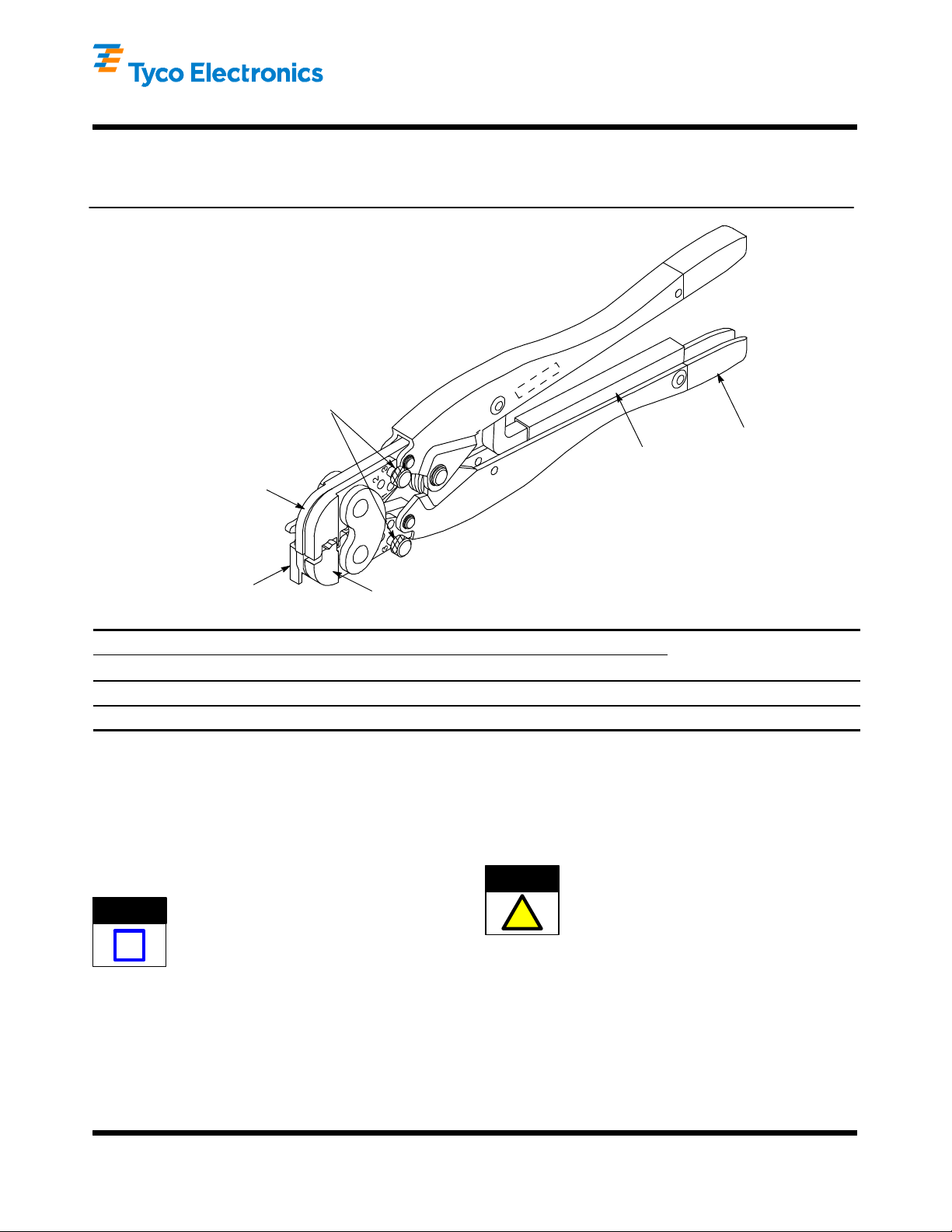
Insulation Crimp Adjustment Pins
(ShowninPosition3)
Ratchet
Fixed Jaw
(Crimper)
411--1097
27 MAY 10 Rev D525690 and 525691
Color--Coded
Handle
Locator/Insulation
Stop
Part Number Color Code Dot Code
525690 Red 1 20--18
525691 Blue 2 16--14
Movable Jaw
(Anvil)
TE Tool
1. INTRODUCTION
Double Action Hand Crimping Tools 525690 and
525691 crimp a wide variety of PIDG* terminals and
splices and PLASTI-- GRIP* terminals and splices
onto stranded copper wire sizes 20 through 14 AWG.
See Figure 1. Read these instructions thoroughly
before using the tools.
NOTE
Dimensions in this instruction sheet are in
millimeters [with inches in brackets]. Figures are
i
not drawn to scale.
Reasons for reissue of this instruction sheet are
provided in Section 7, REVISION SUMMARY.
2. DESCRIPTION
Each tool features a fixed jaw (crimper), a movable
jaw (anvil), a locator/insulation stop, and a ratchet
attached to a handle.
Wire Size Range
(AWG)
Figure 1
These tools are members of the CERTI--CRIMP*
hand crimping tool family. The ratchet on these tools
ensures full crimping of the product. Once engaged,
the ratchet will not release until the handles have
been FULLY closed.
CAUTION
The jaws bottom before the ratchet releases. This
design ensures maximum electrical and tensile
!
performance of the crimp. DO NOT re--adjust the
ratchet.
The locator/insulation stop positions the product
between the jaws and aids in locating the wire in the
product. When closed, the jaws form a crimping
chamber with two sections: an insulation barrel
section and a wire barrel section. The insulation barrel
section crimps the insulation barrel of the product
onto the wire insulation and, simultaneously , the wire
barrel section crimps the wire barrel of the product
onto the wire conductors.
E2010 Tyco Electronics Corporation, Berwyn, PA
All Rights Reserved
TE logo and Tyco Electronics ar e trademarks.
*Trademark. Other product names, logos, or company names might be trademarks of their respective owners.
TOOLING ASSISTANCE CENTER 1--800--722--1111
PRODUCT INFORMATION 1--800--522- -6752
This controlled document is subject to change.
For latest revision and Regional Customer Service,
visit our website at www.tycoelectronics.com
1 of 7
LOC B
Page 2
Double Action Hand Crimping Tools 525690 and 525691
P
r
oduct ColorCode
411- 1097
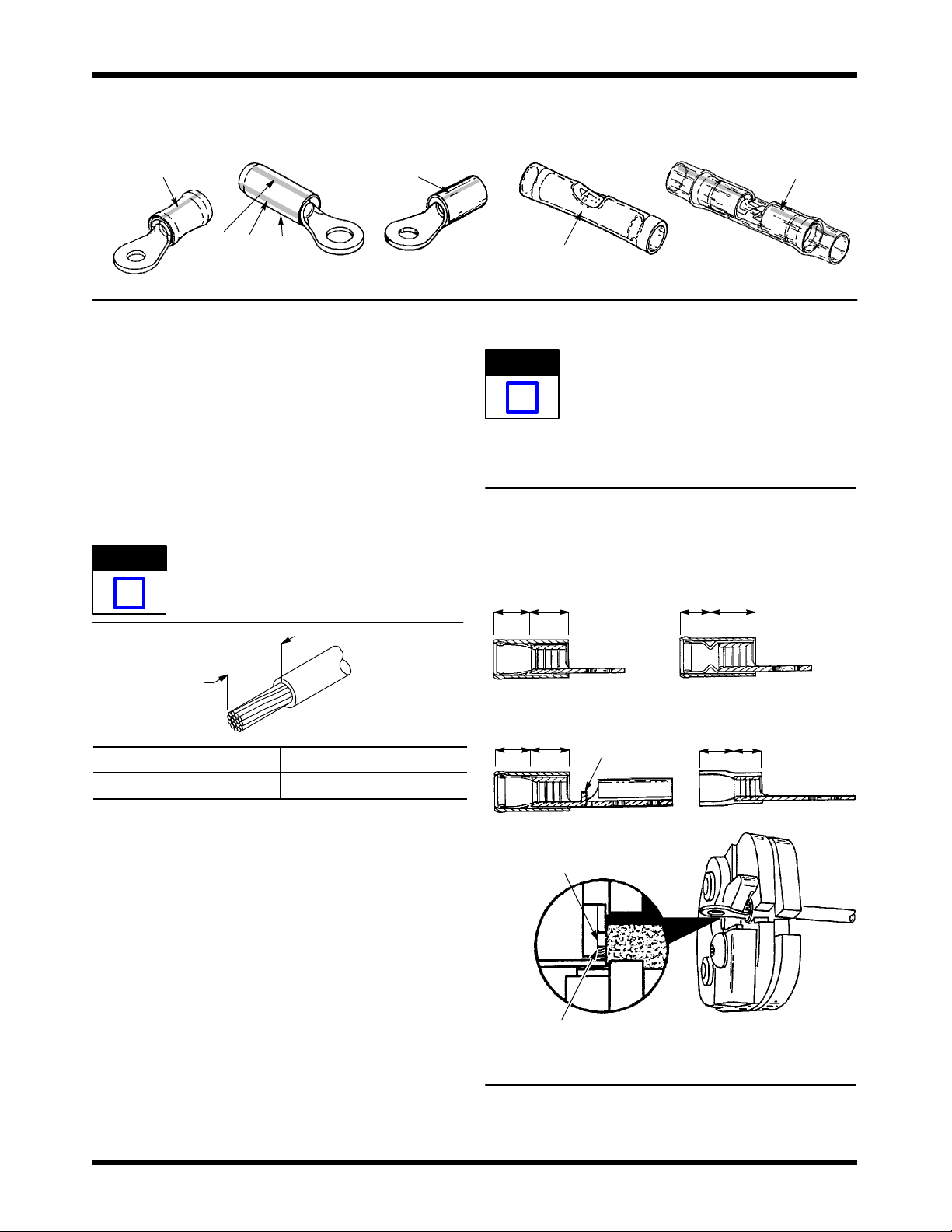
PLASTI--GRIP TerminalPIDG Terminals PIDG Butt Splice
Color Stripe on
Radiation Resistant
3 Equally Spaced
Color Stripes on
Insulation Restricting
Each tool handle is color coded to correspond to the
color code of the product (refer to Figure 2). Each tool
produces a dot code on the crimp to correspond to
the given wire size range (refer to Figure 1).
Color Stripe on
Heavy Duty
3. CRIMPING PROCEDURE
1. Strip the wire to the dimension given in Figure 3,
being careful to avoid nicking or damaging the
conductors.
NOTE
DO NOT use wire with nicked or missing
conductors.
i
PLASTI--GRIP
Color of Insulation
Figure 2
NOTE
Butt Splice
DO NOT allow the wire insulation to enter the
wire barrel.
Color Stripe on
Radiation Resistant
i
7. Close the tool handles until the ratchet releases.
Crimping a Terminal
“B” Equals Wire Barrel
“C” Equals Insulation Barrel
PIDG Terminal
“C” “B”
PIDG Insulation
Restricting Terminal
“C” “B”
Strip Length
Terminal Splice
5.08--5.84 [.20--.23] 6.35--7.11 [.25--.28]
Figure 3
2. Insert the insulation crimp adjustment pins in the
proper position according to Section 4.
3. Open the tool jaws by closing the handles until
the ratchet releases, then allow the handles to
open FULLY.
4. Place the terminal or splice in the crimping
chamber as shown in Figure 4 (for terminals) or
Figure 5 (for splices).
5. Close the tool handles until the terminal or splice
is held firmly in place. DO NOT deform the wire
barrel.
6. Insert a properly stripped wire into the wire
barrel as shown in Figure 4 (for terminals) or
Figure 5, Detail A (for splices).
PIDG FASTON Terminal PLASTI--GRIP Terminal
“C” “B”
Wire Barrel
Against Locator
End of Wire Conductor
Against Locator or,
If Present, Wire Stop
Wire Stop
Figure 4
“C” “B”
Rev D2 of 7 Tyco Electronics Corporation
Page 3
Double Action Hand Crimping Tools 525690 and 525691
411- 1097
8. Release the tool handles, and allow them to
open FULLY. Remove the crimped terminal or
splice.
9. For splices, position the remaining wire barrel in
the crimping chamber as shown in Figure 5, Detail
B. Repeat Steps 5 through 8.
10. Inspect crimped terminal or splice by checking
the features described in Figure 6. Terminals and
splices not meeting the described conditions
should NOT be used.
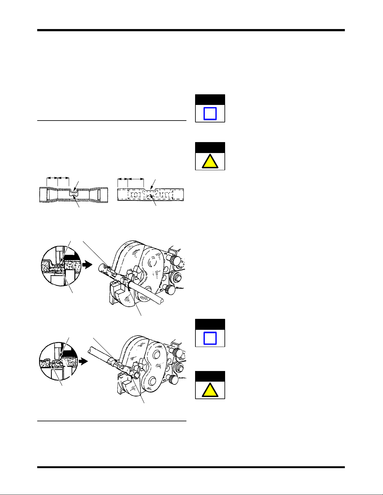
Crimping a Butt Splice
“B” Equals Wire Barrel
“C” Equals Insulation Barrel
“C” “B”
Detail A
PIDG Splice
Window
Indent
Wire Stop
Locator Seats in
Window Indent
PLASTI--GRIP Splice
“C” “B”
Window
Indent
Wire Stop
4. INSULATION CRIMP ADJUSTMENT
The insulation barrel section of the crimping chamber
has three positions: 1 — tight, 2 — medium, and 3 —
loose. To adjust the grip resulting from the crimp of
the insulation barrel, proceed as follows:
4.1. PIDG Terminals and Splices
NOTE
PIDG terminals and splices feature a wire
“insulation grip.”
i
1. Insert each insulation crimp adjustment pin into
Position 3. Refer to Figure 1.
CAUTION
!
2. Position the terminal or splice in the crimping
chamber as described in Section 3.
3. Insert an UNSTRIPPED wire into ONLY the
insulation barrel of the terminal or splice.
4. Close the tool handles until the ratchet releases.
5. Release the tool handles, and allow the handles
to open FULLY. Remove the crimped terminal or
splice.
Make sure that both insulation crimp adjustment
pins are in the same position.
End of Wire Conductor
Against Splice Wire Stop
Detail B
Locator Seats in
Window Indent
End of Wire Conductor
Against Splice Wire Stop
Figure 5
Wire Barrel
Remaining
Wire Barrel
6. Check the insulation barrel crimp by bending the
wire back and forth once. The terminal or splice
should retain its grip on the wire insulation. If it
does not, insert each insulation crimp adjustment
pin into the next position (Position 2).
7. Repeat Steps 2 through 6 until the correct
insulation barrel grip is attained. DO NOT use a
tighter position than is necessary.
4.2. PLASTI- GRIP Terminals and Splices
NOTE
i
Insert each insulation crimp adjustment pin into
position according to the following:
CAUTION
PLASTI--GRIP terminals and splices feature a
wire “insulation support” only. Ideally, the terminal
or splice insulation should be in contact with the
wire insulation.
Make sure that both insulation crimp adjustment
pins are in the same position.
!
— Position 3 for wire having a large insulation
diameter.
— Position 2 for wire having a medium insulation
diameter.
— Position 1 for wire having a small insulation
diameter.
3 of 7Rev D Tyco Electronics Corporation
Page 4

Double Action Hand Crimping Tools 525690 and 525691
Crimp Inspection
Dot Code (1 or 2 Dots) Must Appear on All Crimps
411- 1097
PIDG Terminals and PLASTI--GRIP Terminals
1
3
4
2
5
7 8
6
PLASTI--GRIP Butt Splices
3
5
6
2
4
7
PIDG Butt Splices
3
8
6
Wire Stop
4
6
2
1a
1
Insulation barrel is in firm contact with wire insulation
2
Correct color code, dot code, and tool combination
Wire size is within wire size range stamped on terminal
3
tongue
4
Crimp is centered on wire barrel
Conductor end is flush with, or extends beyond, end of
5
wire barrel
Conductor end is against the wire stop, or is at least
6
flush with or extends slightly beyond wire barrel
7
Wire insulation does not enter wire barrel
8
No nicked or missing wire conductor strands
1b
Wire Stop
1
Splice insulation (a) or insulation barrel (b) is in contact
with wire insulation
2
Correct color code, dot code, and tool combination (dot
coding disappears from sealed splices when heat sealed)
Wire size is within wire size range stamped on center
3
of splice
4
Crimp is centered on wire barrel
No flash or extruded insulation
5
Conductor end is against wire stop, or is at least flush
6
with or extends slightly beyond wire barrel
7
Wire insulation does not enter wire barrels
8
No nicked or missing conductor strands
Figure 6
Rev D4 of 7 Tyco Electronics Corporation
Page 5

Double Action Hand Crimping Tools 525690 and 525691
nfi
gurat
ion
411- 1097
5. MAINTENANCE AND INSPECTION
It is recommended that a maintenance and inspection
program be performed periodically to ensure
dependable and uniform terminations. Though
recommendations call for at least one inspection a
month, frequency of inspection depends on:
1. The care, amount of use, and handling of the
tool.
2. The presence of abnormal amounts of dust and
dirt.
3. The degree of operator skill.
4. Your own established standards.
The tool is inspected before being shipped; however,
it is recommended that the tool be inspected
immediately upon arrival to ensure that the tool has
not been damaged during shipment.
5.1. Daily Maintenance
1. Immersed the tool (handles partially closed) in a
reliable commercial degreasing compound to
remove accumulated dirt, grease, and foreign
matter. When degreasing compound is not
available, the tool may be wiped clean with a soft,
lint--free cloth. DO NOT use hard or abrasive
objects that could damage the tool.
2. Make certain that the retaining pins are in place
and that they are secured with retaining rings.
3. All pins, pivot points, and bearing surfaces
should be protected with a THIN coat of any good
SAE 20 motor oil. DO NOT oil excessively.
4. When the tool is not in use, keep the handles
closed to prevent objects from becoming lodged in
the jaws. Store the tool in a clean, dry area.
5.2. Periodic Inspection
open quickly and fully, the spring is defective and
must be replaced. See Section 6, REPLACEMENT
AND REPAIR.
2. Inspect the head for worn, cracked, or broken
jaws. If damage is evident, return the tool for
evaluation and repair. See Section 6,
REPLACEMENT AND REPAIR
C. Gaging the Crimping Chamber
This inspection requires the use of plug gages
conforming to the dimensions provided in Figure 7.
To gage the crimping chamber, proceed as follows:
1. Remove traces of oil or dirt from the crimping
chamber and plug gage.
2. Insert each insulation crimp adjustment pin into
Position 1. See Figure 8.
NO--GO DiaGO Dia
Jaw Closure
Co
SUGGESTED PLUG GAGE DESIGN
FOR WIRE BARREL SECTION
TOOL
525690 2.768--2.776 [.1090--.1093] 2.918--2.921 [.1149--.1150]
525691 3.022--3.030 [.1190--.1193] 3.172--3.175 [.1249--.1250]
GO Dia NO--GO Dia
W
Jaw Closure
Configuration
GAGE ELEMENT DIAMETER
GO NO--GO
GO
NO
GO
W
A. Lubrication
SUGGESTED PLUG GAGE DESIGN
Lubricate all pins, pivot points, and bearing surfaces
with any good SAE 20 motor oil as follows:
Tool used in daily production — daily
TOOL
Tool used daily (occasional) — weekly
Tool used weekly — monthly
Wipe excess oil from the tool, particularly from the
crimping area. Oil transferred from the crimping area
525690
525691
onto certain terminations may affect the electrical
characteristics of an application.
B. Visual Inspection
1. Close the tool handles until the ratchet releases
and then allow them to open freely. If they do not
3. Close the tool handles until the jaws bottom,
and hold in this position. DO NOT force beyond
initial contact.
FOR INSULATION BARREL SECTION
GAGE ELEMENT THICKNESS
GO
0.889--0.897
[.0350--.0353]
1.143--1.151
[.0450--.0453]
NO--GO W
1.394--1.397
[.0549--.0550]
1.648--1.651
[.0649--.0650]
Figure 7
2.80--3.05
[.110--.120]
4.50--4.75
[.177--.187]
5 of 7Rev D Tyco Electronics Corporation
Page 6

Double Action Hand Crimping Tools 525690 and 525691
Ins
Ins
411- 1097
pectionof
Wire Barrel Section
of Crimping Chamber
Insulation Crimp Adjustment Pins in Position 1
Jaws Bottomed But
Not Under Pressure
GO Element Must Pass
Completely Through
Crimping Chamber
pectionof
Insulation Barrel Section
of Crimping Chamber
GO Element Must Pass
Completely Through Length of
Insulation Barrel Section But
Stop on Wire Barrel Section
correct, and should be lubricated with a THIN coat of
any good SAE 20 motor oil. If not, return the tool for
evaluation and repair. See Section 6,
REPLACEMENT AND REPAIR.
5.3. Ratchet Inspection
Check the ratchet to ensure that the ratchet does not
release prematurely, allowing the jaws to open before
they have fully bottomed. Proceed as follows:
1. Remove traces of oil or dirt from the bottoming
surfaces of the jaws.
2. Obtain a 0.025 mm [.001 in.] shim that is
suitable for checking the clearance between the
bottoming surfaces of the jaws.
3. Select a terminal or splice and maximum size
wire for the terminal or splice.
4. Position the terminal or splice in the crimping
chamber according to Section 3, CRIMPING
PROCEDURE. Holding the wire in place, squeeze
the tool handles together until the ratchet releases.
Hold the tool handles in this position, maintaining
just enough pressure to keep the jaws closed.
5. Check the clearance between the bottoming
surfaces of the jaws. If the clearance is 0.025 mm
[.001 in.] or less, the ratchet is satisfactory. If
clearance exceeds 0.025 mm [.001 in.], the ratchet
is out of adjustment and must be repaired. See
Section 6, REPLACEMENT AND REPAIR.
NO--GO Element May Start Entry, But Must Not
Pass Completely Through Crimping Chamber
Figure 8
4. Carefully insert the GO element into the
crimping chamber as shown in Figure 8; DO NOT
force it. For the wire barrel section of the crimping
chamber, the GO element must pass completely
through the crimping chamber. For the insulation
barrel section, the GO element must pass through
the length of the section but will stop against the
wire barrel section.
5. In the same manner, try to insert the NO--GO
element into the crimping chamber as shown in
Figure 8. The NO--GO element may begin entry,
but may not pass through the crimping chamber.
If the crimping chamber conforms to the gage
inspection, the tool is considered dimensionally
6. REPLACEMENT AND REPAIR
Customer--replaceable parts are listed in Figure 9.
A complete inventory should be stocked and
controlled to prevent lost time when replacement of
parts is necessary. Parts other than those listed
should be replaced by Tyco Electronics to ensure
quality and reliability. Order replacement parts
through your representative, or call 1--800--526--5142,
or send a facsimile of your purchase order to
717--986--7605, or write to:
CUSTOMER SERVICE (038--035)
TYCO ELECTRONICS CORPORATION
PO BOX 3608
HARRISBURG PA 17105--3608
For customer repair service, call 1--800--526--5136.
7. REVISION SUMMARY
Revisions to this instruction sheet include:
S Updated document to corporate requirements
S Added new data to tables in Figure 7
Rev D6 of 7 Tyco Electronics Corporation
Page 7

Double Action Hand Crimping Tools 525690 and 525691
7 8
6
45
9
1 23
411- 1097
3
REPLACEMENT PARTS
ITEM PART NUMBER DESCRIPTION QTY PER TOOL
1 01--23619--6 PIN, Retaining 2
2 525108 RING, Retaining 4
3 039207 PIN, Adjustment 2
4 00--21028--1 PIN 2
5 0--525355--8 LOCATOR 1
6 9--305927--1 SCREW 1
7 302994 HOUSING STOP 1
8 301201 SPRING 1
9 039208 RING 6
Figure 9
7 of 7Rev D Tyco Electronics Corporation
Page 8

Mouser Electronics
Authorized Distributor
Click to View Pricing, Inventory, Delivery & Lifecycle Information:
TE Connectivity:
525691
 Loading...