

Tyco Electronics 24 Port SNMP, 24 Port UTP 10/100Mbit/sEthernet Managed Switch with 2Expansion Slots User Manual
Page 1

24 Port SNMP Managed Switch – User Manual Page 1
Product Number 0-1591058-x © Tyco Electronics 2003 PL0351 Issue 1
24 Port UTP 10/100Mbit/s
Ethernet Managed Switch with 2
Expansion Slots
-
Product User Guide
Introduction
Page 2

24 Port SNMP Managed Switch – User Manual Page 2
Product Number 0-1591058-x © Tyco Electronics 2003 PL0351 Issue 1
Disclaimer
Tyco Electronics makes no representation or warranties with respect to the contents hereof
and specifically disclaims any implied warranties or merchantability or fitness for any
particular purpose. Further, Tyco Electronics reserves the right to revise this publication and
make changes from time-to-time in the content hereof without obligation of Tyco Electronics
to notify any person of such revision or changes.
Features
• Conforms to IEEE802.3, 802.3u, 802.3z, 802.3x, 802.1p, 802.3ac, 802.1D and
802.1Q
• 24 auto-sensing 10/100Mbps Ethernet RJ-45 ports
• 2 Expansion slots for optional modules:
o 1-port Duplex SC Gigabit (SX/LX),
o 100Mbps Fiber (SC multimode and singlemode and MT-RJ),
o 10/100/1000Mb/s UTP with auto-negotiation and MDI/MDIX
• Store - And - Forward error free packet forwarding scheme
• 8K-entry MAC address table
• 128 VLANs
• 32 Multicast groups
• 6Mb shared memory
• 9.6 GB Backplane Bandwidth
• Full wire speed forwarding rate
• LED-indicators for Power, port speed/Link/Active, FDX/COL
• 10/100/1000M Gigabit Module LK/ACT, FDX/ COL status
Intelligent Management Features
• Console and Telnet Configuration
• Web-based management
• SNMP network management
• Asymmetrical bandwidth limiting and control on each port
• Port based VLANs
• MTU/MDU VLANs
• Tagged VLANs using IEEE802.1Q
• Programmable QoS
• Spanning Tree Protocol
• IGMP Snooping protocol supported
• Port mirroring
• TFTP support for firmware downloads
• RMON Statistics
Page 3
24 Port SNMP Managed Switch – User Manual Page 3
Product Number 0-1591058-x © Tyco Electronics 2003 PL0351 Issue 1
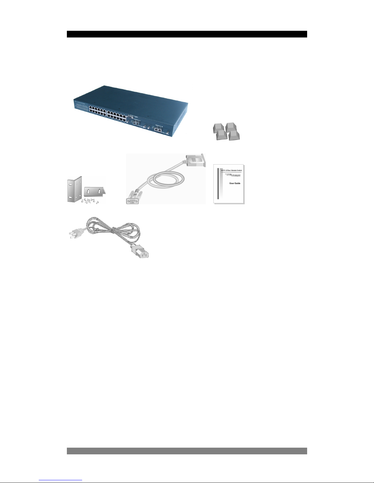
Package Contents
Unpack the carton of the 24 Port SNMP Managed Switch and verify them against the
checklist below.
24 Port SNMP Managed Switch Rubber Feet
Rack-mounted Kit RS-232 cable User Guide
Power Cord
Figure 1. Package Contents
Compare the contents of your 24 Port SNMP Managed Switch package with the standard
checklist above. If any item is missing or damaged, please contact your local dealer for
service.
Page 4

24 Port SNMP Managed Switch – User Manual Page 4
Product Number 0-1591058-x © Tyco Electronics 2003 PL0351 Issue 1
Management Methods
The 24 Port SNMP Managed Switch supports following management methods:
• Console and Telnet Management
• Web-based Management
• SNMP Network Management
Console and Telnet Management
Console Management is done through the RS-232 Console Port. Managing the 24 Port
SNMP Managed Switch in this method requires a direct connection between PC and the 24
Port SNMP Managed Switch. While Telnet management is done over the network. Once the
24 Port SNMP Managed Switch is on the network, you can use Telnet to log in and change
the configuration. The automatic log-out times can be programmed and are detailed on pages
36 and 56. See page 12 for details.
Web Based Management
The switch can be managed using a standard web browser that supports Java applets. This
interface has the same functionality as the console/Telnet interfaces but is more user-friendly.
See page 38 for details.
SNMP Network Management
SNMP (Simple Network Management Protocol) provides a means to monitor and control a
network device, and to manage configurations, statistic collection, performance and security.
Data is passed from SNMP agents, which are hardware & software processes reporting
activity in each network device to the workstation console used to oversee the network. The
agent returns information contained in a MIB (Management Information Base), which is a data
structure that defines what is obtainable from the device and what can be controlled.
Page 5
24 Port SNMP Managed Switch – User Manual Page 5
Product Number 0-1591058-x © Tyco Electronics 2003 PL0351 Issue 1
Hardware Description
The 24 Port SNMP Managed Switch has fixed 24-port auto-sensing Ethernet RJ-45
connectors, and a chassis containing two expansion slots. The optional modules enable the
switch to be used in new and legacy networks.
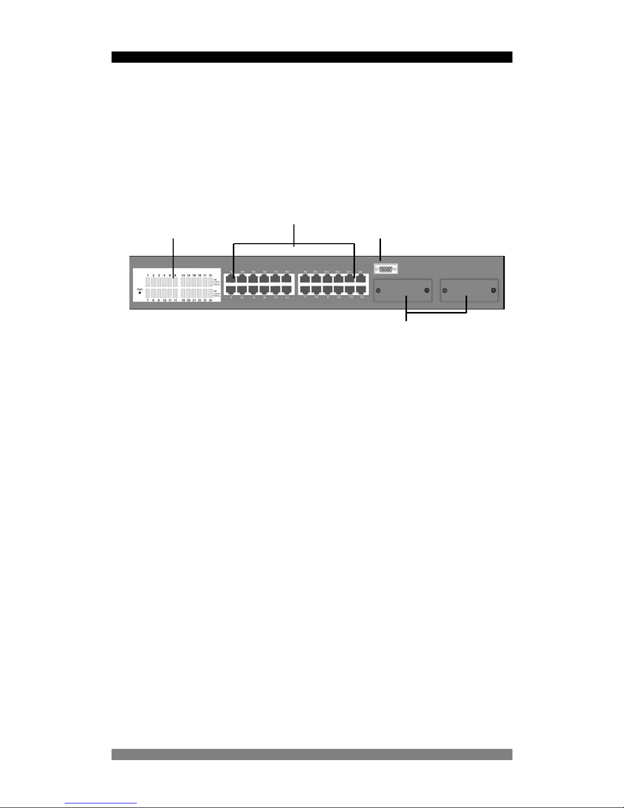
The Front Panel
The front panel of the switch consists of 24 x auto-sensing 10/100Mbps Ethernet RJ-45 Ports,
two optional expansion slots, and console port. The LED Indicators are also located on the
front panel of the Switch.
Figure 2. The Front Panel of 24 Port SNMP Managed Switch
10/100Base-TX Auto MDI/MDIX RJ-45 Ports
The switch has 24 x 10/100Mbps auto-sensing ports for 10Base-T or 100Base-TX device
connection. The auto-MDI/MDIX function enables the direct connection another switch or
workstation without needing to select either a straight or cross-over cable.
Expansion Slots
The switch can support up to two of the following optional single port modules, which can be
used in any combination:
• 10/100/1000Mbps Auto-MDI/MDI-X RJ-45 module
• 1000Base-SX multimode fiber module
• 1000Base-LX singlemode fiber module
• 100Base-FX SC multimode fiber module
• 100Base-FX MT-RJ multimode fiber module
• 100Base-FX SC singlemode fiber module
LED Indicators
RJ-45 Ports
Console Port
Expansion Slots for Option Modules
Page 6
24 Port SNMP Managed Switch – User Manual Page 6
Product Number 0-1591058-x © Tyco Electronics 2003 PL0351 Issue 1
Console Port
The switch can be fully managed using the console port providing a direct connection
between the switch and an end station such as a PC via the supplied RS-232 cable.
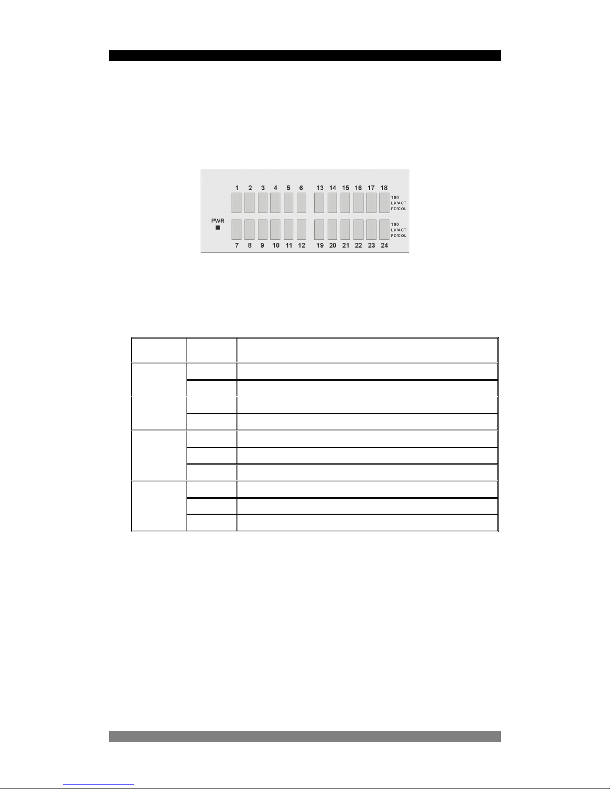
LED Indicators
Figure 3. The LED Indicators
All LED indicators are located on the front panel of the 24 Port SNMP Managed Switch and
provide a real-time indication of switch and operational status. The following table details the
LED states:-
LED Status Description
Green Power On
PWR
Off Power is Off.
Green The port is operating at the speed of 100Mbps.
100
Off No device is attached or in 10Mbps mode
Green The port is connected to an Ethernet device.
Blinks The port is receiving or transmitting data
LK/ACT
Off No device is attached
Orange The port is operating in Full-duplex mode
Blinks Collision of packets is occurring on the port
FD/COL
Off No device is attached or the port is in half-duplex mode
Figure 4. Descriptions of LED Indicators
Page 7
24 Port SNMP Managed Switch – User Manual Page 7
Product Number 0-1591058-x © Tyco Electronics 2003 PL0351 Issue 1
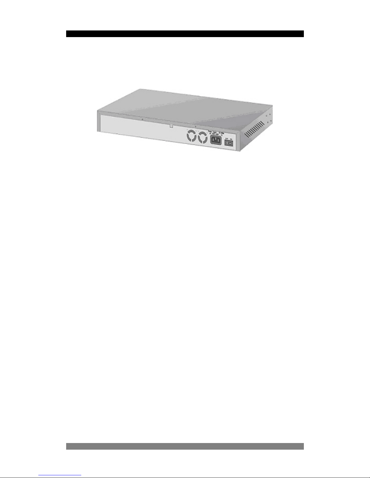
Rear Panel
The 3-pronged power socket and the On/Off switch are located at the rear panel of the switch.
The switch operates over the range 100-240V AC, 50-60Hz without adjustment.
Figure 5. The Rear Panel of the 24 Port SNMP Managed Switch
Diagnostic Test
After the installation is completed and AC power is applied to the Switch, the system will
automatically perform a diagnostic test. If a console session is active at this time then it is
possible to see each stage of this start-up and test procedure as it is carried out.
This procedure will take up to 5 minutes to complete. Upon completion the switch will start in
a default condition and begin to pass traffic.
Page 8
24 Port SNMP Managed Switch – User Manual Page 8
Product Number 0-1591058-x © Tyco Electronics 2003 PL0351 Issue 1
Installation
.
Pre-Installation Requirements
Before you start hardware installation, make sure your installation environment has below
items:
PC with 10/100Mbps Ethernet NICs / 100Mbps Fiber NICs:
Your PC must have a standard Ethernet RJ-45 interface to connect to the Switches copper
port.
UTP cable with RJ45 connectors: Ensure that you use a tested cable.
AC Power: 100 to 240V AC at 50/60 Hz: Make sure that the power is accessible and the
AC power cable can be and disconnected and connected easily.
Dedicated power supply: Use dedicated AC or power conditioners to supply reliable
electrical power to the network devices.
A dry cool place: Keep the Switch away from moisture. Avoid direct sunlight, sources of
heat, and a high amount of electromagnetic interference.
Mounting tools: If you intend to mount the Switch in a rack, make sure you have all the
tools, mounting brackets, screws etc.
Caution:
Cabling must be away from sources of electrical noise such as radio, computers, transmitters,
broadband amplifiers, power lines etc.
Airflow around the Switch and through its vents on the rear must not be restricted.
Mounting the Switch
The 24 Port SNMP Managed Switch is suitable for use in an office environment where it can
be rack-mounted in standard EIA 19-inch racks or standalone.
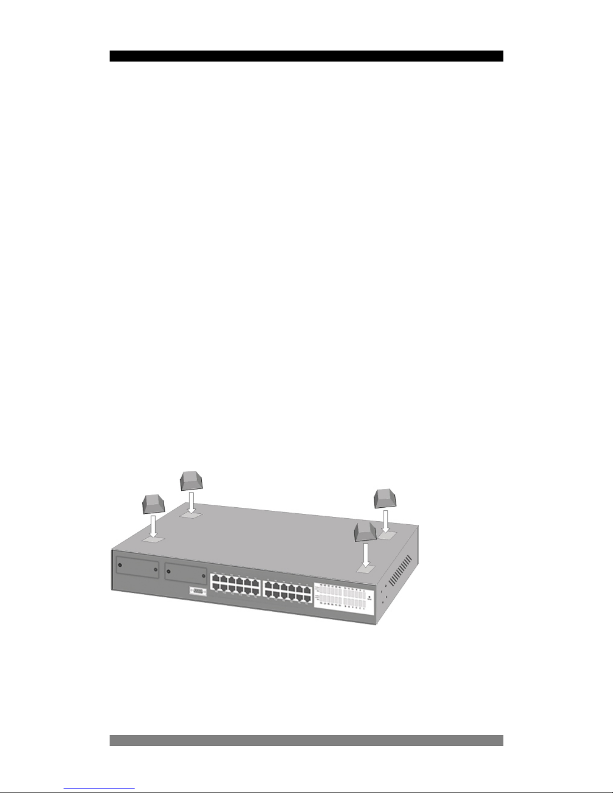
Desktop Mounting
Set the Switch on a sufficiently large flat space with a power outlet nearby, and near the
center of all networked devices.
Make sure mounting surface on the bottom of the Switch is grease dust free.
Remove adhesive backing from your Rubber Feet.
Figure 3-1. Attaching Rubber Feet to each corner on the bottom of the
Switch
Apply the Rubber Feet to each corner on the bottom of the Switch. These footpads can
prevent the Switch from shock/vibrations.
Caution: Do not place objects on top of the Switch.
Page 9
24 Port SNMP Managed Switch – User Manual Page 9
Product Number 0-1591058-x © Tyco Electronics 2003 PL0351 Issue 1
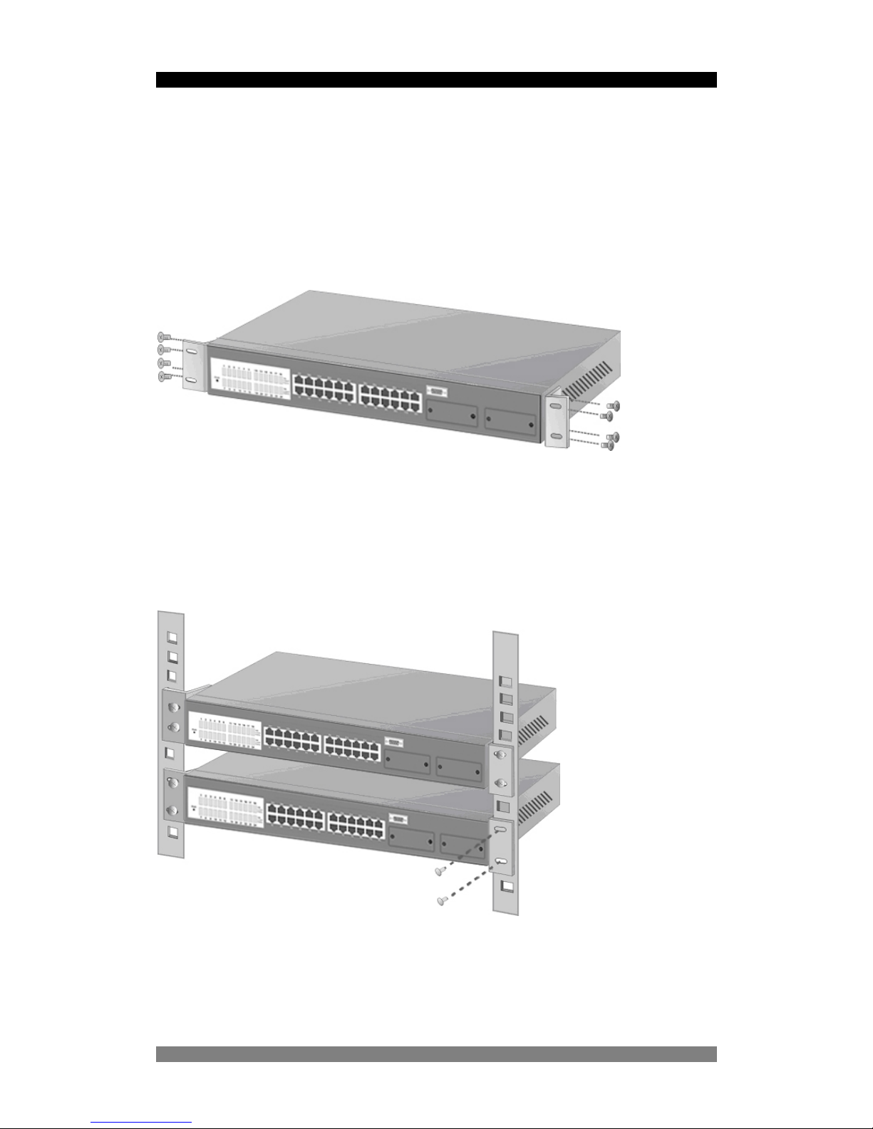
Rack-mounted Installation
The 24 Port SNMP Managed Switch is supplied with a rack-mounted kit and can be mounted
in an EIA standard size, 19-inch rack. The Switch can be placed in a wiring closet with other
equipment.
Perform the following steps to rack mount the Switch:
Position one bracket to align with the holes on one side of the Switch and secure it with the
smaller bracket screws. Then attach the remaining bracket to the other side of the Switch.
Figure 3-2. Attach mounting brackets with screws
After attaching both mounting brackets, position the switch in the rack by lining up the holes in
the brackets with the appropriate holes on the rack. Secure the switch to the rack with the
rack-mounting screws.
Figure 3-3. Mount the 24TP+1Fiber Module Switch in an EIA standard 19inch Rack
Note: For proper ventilation, allow about at least 4 inches (10 cm) of clearance on the front
and 3.4 inches (8 cm) on the back of the Switch. This is especially important for enclosed rack
installation.
Page 10
24 Port SNMP Managed Switch – User Manual Page 10
Product Number 0-1591058-x © Tyco Electronics 2003 PL0351 Issue 1
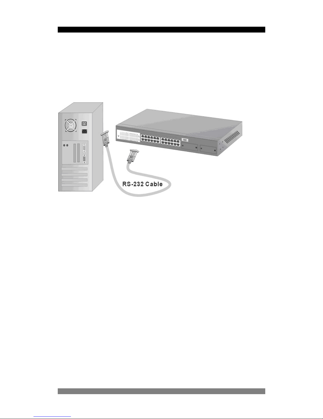
Connecting to the Switch
The Console port is a male DB-9 connector located on the front panel of the switch that
enables a connection to a PC or terminal for monitoring and configuration. Use the supplied
RS-232 cable with a female DB-9 connector to connect a terminal or PC to the Console port.
The Console configuration allows you to program the Switch to enable a user at a remote
location to communicate with the unit as if the console terminal were directly connected.
Figure 3-4. Connecting the 24 Port SNMP Managed Switch to a terminal via
RS-232 cable
Page 11

24 Port SNMP Managed Switch – User Manual Page 11
Product Number 0-1591058-x © Tyco Electronics 2003 PL0351 Issue 1
Quick Start Guide
If you do not need to apply VLANs, Quality of Service, adjust any settings or manage the
switch via the network, then the switch can be used “straight-from-the-box” to carry network
traffic. In that case, no further action is needed. If you want to use the management settings
or controls, then a little work is needed to configure the switch.
1. After the installation is completed and AC power is applied to the switch, the unit will
automatically perform a diagnostic test. The switch loads its operating code from memory
and performs a full power-on self test. The screen will display the self-test progress, but
do not press any keys at this stage. This power-up sequence takes approx. 90 seconds to
complete. The web interface will take a further 30 seconds to become operational.
2. Configure you PC terminal emulation program such as HyperTerminal to allow it to
communicate with the switch via the supplied serial cable connected to the front panel
Console port. Set the emulation program for 9600, 8, No Parity, No Flow Control. See
page 12 for details
3. When the password and user name prompt is displayed, use the default username of
root in lower case letters. Use the password root. The main menu screen will be
displayed. Use either cursor keys or the tab key to navigate up and down the menu.
Select the item using the <CR> key. The <ESC> key will return you to the previous menu
level.
4. If the switch is to be managed over the LAN using the Telnet, SNMP or the web browser
functions, then an IP address is to be assigned to the switch. See page 14 for details. If
the switch is not being managed over the LAN, then go to page 12 below.
5. Once an IP address has been assigned to the switch, it should be possible to PING the
switch over the network. This will prove that the switch is present and responding
correctly to network requests. See page …. For details.
6. Now that the switch can be accessed over the network, use a browser application to open
up the configuration screens. Enter the switch IP address into the browser Address
window and use the same user name and password set as in 3 above.
7. Using the preferred method (console, Telnet or web browser), configure the switch to
meet your network requirements. Always save the configuration at the end of each action.
8. If you need to revert the switch back to the factory default configuration, then see page 36
or page 55.
Page 12
24 Port SNMP Managed Switch – User Manual Page 12
Product Number 0-1591058-x © Tyco Electronics 2003 PL0351 Issue 1
Management Using The Console
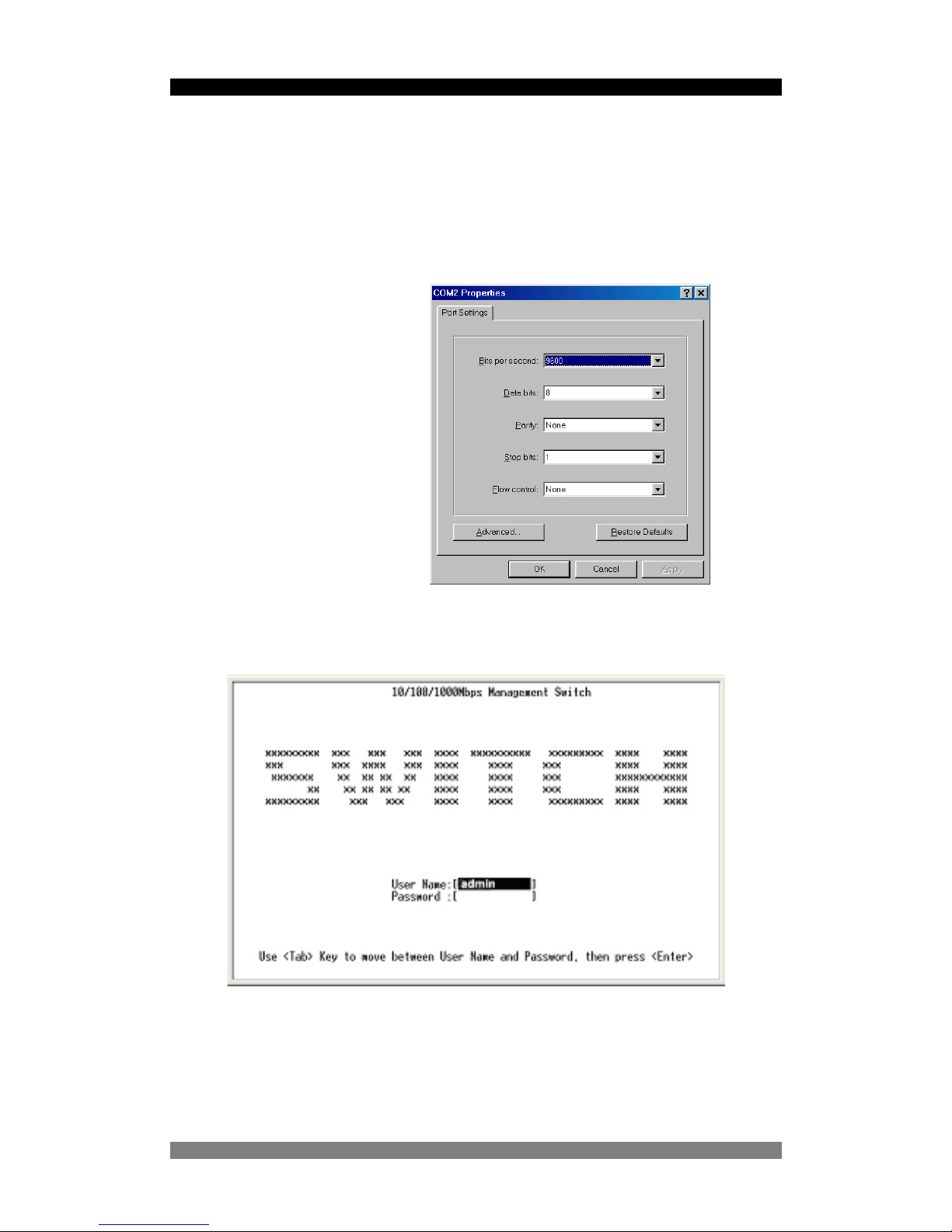
Configuring the Console Interface
When the connection between Switch and PC is complete, turn on the PC and run a terminal
emulation program such as Hyper Terminal and configure its communication parameters to
match the following default characteristics of the console port:
Baud Rate: 9600 bps
Data Bits: 8
Parity: none
Stop Bit: 1
Control flow: None
Figure 6. The settings of communication parameters
Figure 7. Initial Start-Up Screen
After you have finished parameter settings, click “OK“ on the PC. When the screen shows
above, enter root in lower case letter for the User Name, and enter the<CR> or return key
twice. A password is required for the default root name the password is root. The Main Menu
of console management appears.
Page 13

24 Port SNMP Managed Switch – User Manual Page 13
Product Number 0-1591058-x © Tyco Electronics 2003 PL0351 Issue 1
Main Menu Screen
After login you will see the Main Menu screen below. Use the <tab> or cursor keys to step
through the sub-menus. Select the required sub-menu using the <CR> or enter key.
Figure 8. Main Menu Screen
System Information
The sub-menu screen displays information such as switch hardware, software versions, and
system up time. You can also enter specific information about you and your organization
here. Ensure that the setting are saved using the Save function.
Page 14
24 Port SNMP Managed Switch – User Manual Page 14
Product Number 0-1591058-x © Tyco Electronics 2003 PL0351 Issue 1
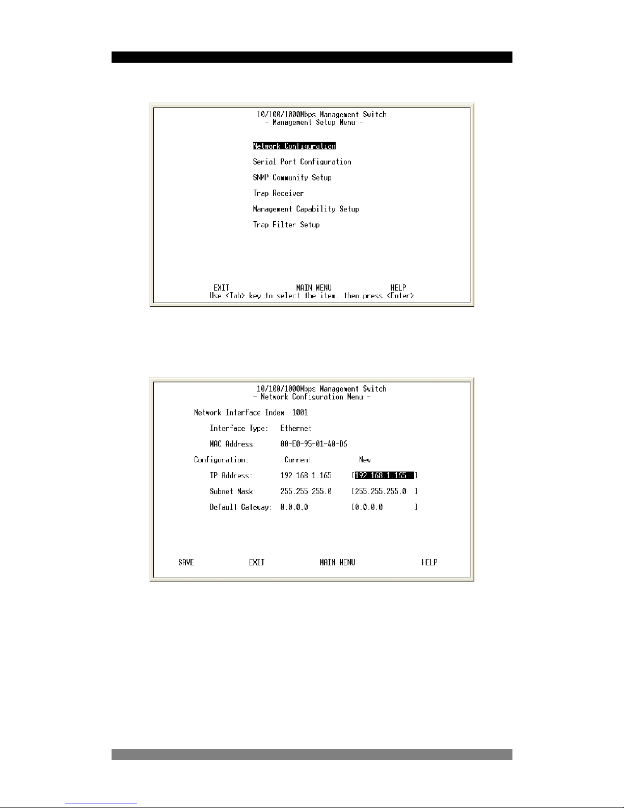
Management Setup Menu Screen
Figure 9. The Management Setup Menu
The management setup menu contains 6 submenus and are discussed below.
Network Configuration Menu
Figure 10. The Network Configuration Menu
This menu displays the switch MAC address and enables the IP address of the switch to be
configured to the network. To change the IP switch setting: -
1. Use the <TAB> or cursor keys to highlight the New IP Address field.
2. Enter the new IP Address as required.
3. Use <TAB> or cursor keys to highlight the New Subnet Mask field.
4. Enter the new Subnet mask address as required.
5. Use <TAB> or cursor keys to highlight the default gateway field.
6. Enter the IP address of the default gateway as required.
7. Use the <TAB> or cursor keys to highlight the Save field and then select the Save
using the <CR or Return> key to save the IP address changes.
Page 15
24 Port SNMP Managed Switch – User Manual Page 15
Product Number 0-1591058-x © Tyco Electronics 2003 PL0351 Issue 1
8. The changes that have been made will only appear in the “New” column but not in the
current column, to activate the new settings and make them current the switch will
need restarting. See section 5.1 for how to restart switch.
After restarting the switch it is advisable to check that changes have been made current by
checking the network configuration menu again.
The following menu options enable detailed changes to the serial port and SNMP
configuration. These menus are not used in most instances.
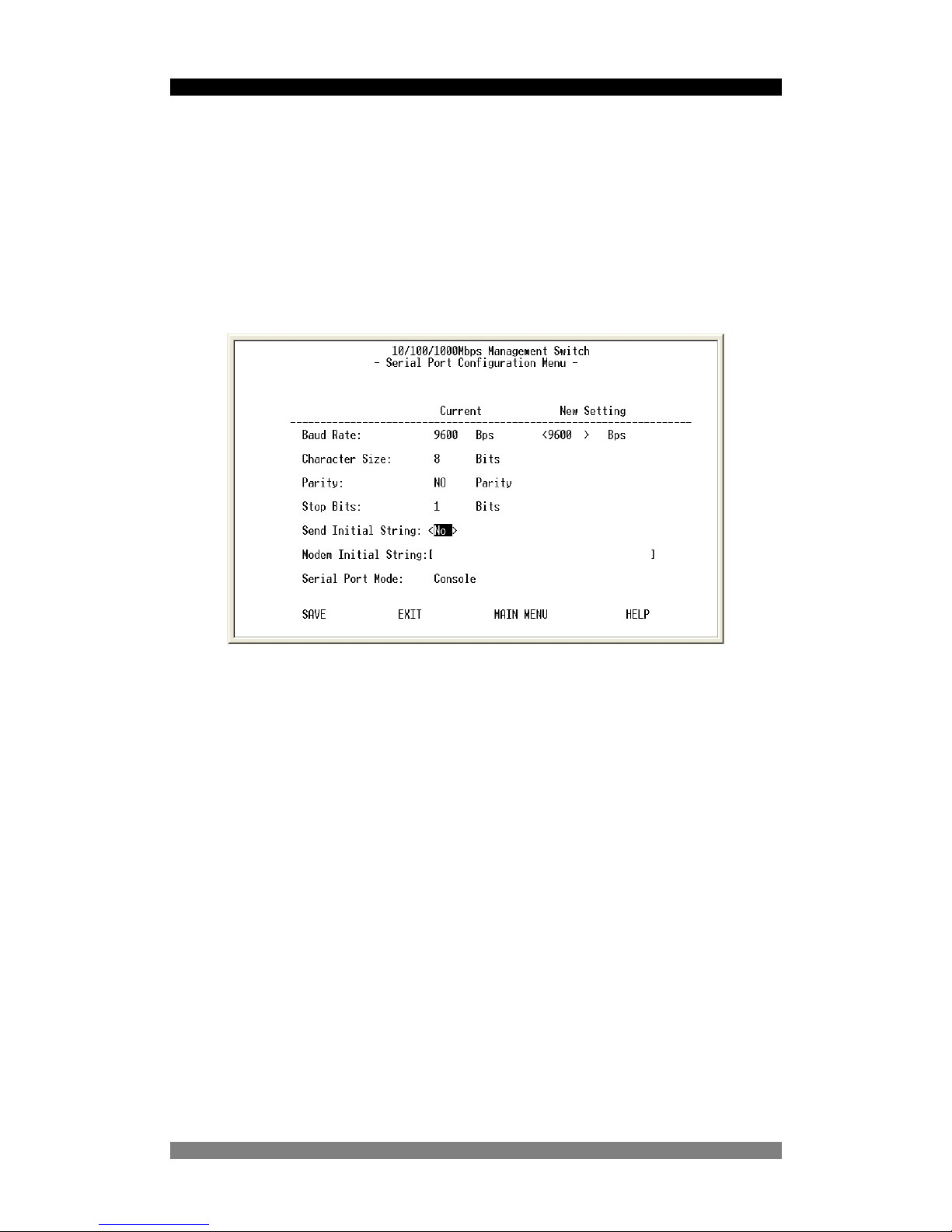
Serial Port Configuration Menu
Figure 11. The Serial Port Configuration
Although you can change the serial link characteristics, we strongly recommend that the
above default values are retained.
Page 16
24 Port SNMP Managed Switch – User Manual Page 16
Product Number 0-1591058-x © Tyco Electronics 2003 PL0351 Issue 1
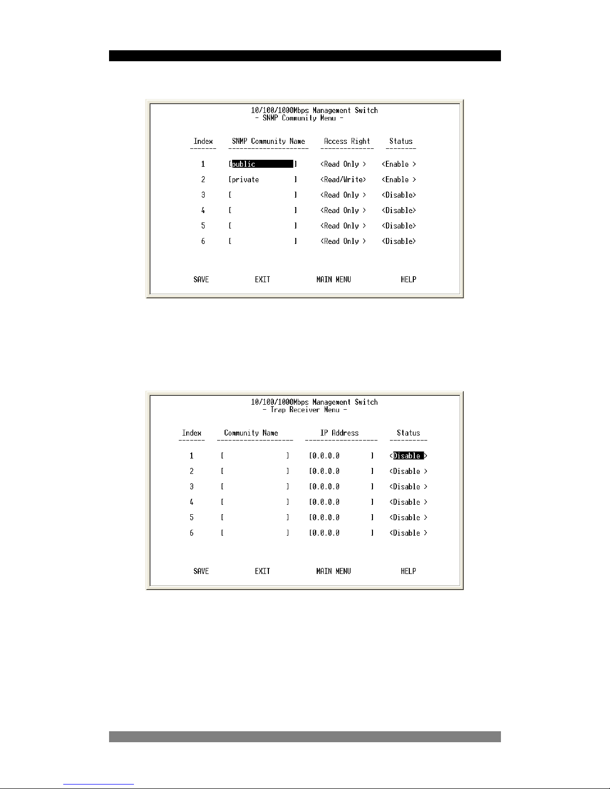
SNMP Community Setup Menu
Figure 12. The SNMP Community Menu
In the SNMP Community Menu, you can create different communities and customize their
access rights. Use <TAB> or cursor keys to move the highlight bar and select desired
community to modify or add a new community (use space bar to toggle the access right and
status values).
Trap Receiver Menu
Figure 13. The Trap Receiver Menu
Use trap receiver screen to designate a certain community to receive trap(s) generated by the
switch.
Page 17
24 Port SNMP Managed Switch – User Manual Page 17
Product Number 0-1591058-x © Tyco Electronics 2003 PL0351 Issue 1
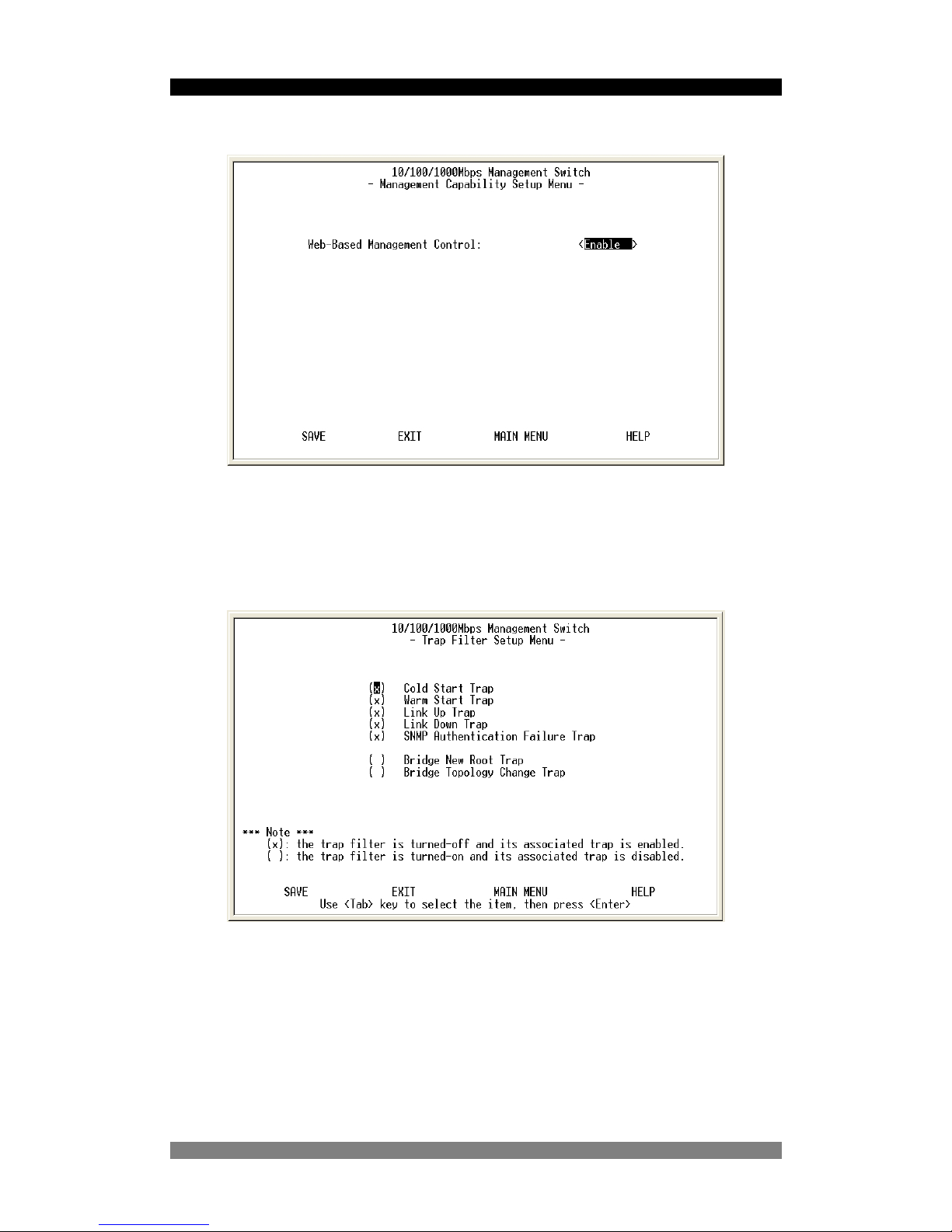
Management Capability Setup Menu
Figure 14. The Management Capability setup Menu
This menu option allows the web based management facility to be enabled or disabled. This
is achieved by using the <space> bar to toggle between Enable and Disable states. It is
recommended that a modern Java based Internet Explorer or Netscape Navigator browser be
used.
Trap Filter Setup Menu
Figure 15. The Trap Filter Setup menu
The switch can generate a set of SNMP traps upon the occurrence of certain events. By
marking the filter box with a check, the filter is disabled and this will allow the generation of a
trap associated with that event. Toggle the check box using the <space> key.
Page 18
24 Port SNMP Managed Switch – User Manual Page 18
Product Number 0-1591058-x © Tyco Electronics 2003 PL0351 Issue 1
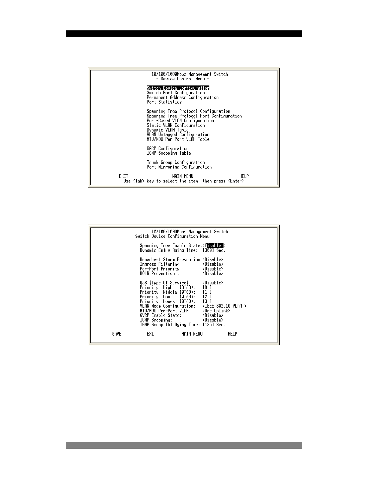
Device Control Menu
This is a high level menu that controls much of the configuration of the switch.
Figure 16 . The Device Control menu
Move the <Tab> or cursor keys to highlight the required function and the press the <CR or
Return> key to select the function.
Switch Device Configuration Menu
Figure 17. The Switch Device Configuration Menu
This menu sets numerous key functions and modes for the entire switch. It is recommended
that the required modes are set using this menu before attempting to configure port details.
Page 19

24 Port SNMP Managed Switch – User Manual Page 19
Product Number 0-1591058-x © Tyco Electronics 2003 PL0351 Issue 1
The Switch Device Configuration menu options are listed below. Use the <space> bar to
toggle modes, or enter time values directly:-
• The Spanning Tree Protocol for the switch is enabled or disabled in this menu.
• The Dynamic Ageing Time is the number of seconds that an entry will be stored in
the switch ARL table before it is aged out. The default is 300 seconds, but in some
test applications, it may be desirable to reduce this time.
• Ingress filtering when enabled the switch will reject all tagged VLAN traffic not
intended for the port that is receiving the tagged packet.
• The Per Port Priority control allows the ports to be allocated specific priority values
from the Switch Port Configuration menu.
• The HOLB Prevention control either enables or disables Head Of Line Blocking. This
is an advanced function associated with egress flow control and heavily loaded
networks where it is desirable to constrain the use of switch buffers to protect other
ports. It is recommended that this control is left in the <enabled> state for normal
network applications.
• When QoS (Quality of Service) is enabled you can map the Type of Service of your
choice (according to IEEE 802.1p) to the four priority levels provided.
• The switch supports three different VLAN modes:-
o Port Based VLAN,
o IEEE 802.1Q VLAN
o MTU/MDU VLAN.
The choice made here will ultimately decide the VLAN mode and function for the entire
switch. See Below for VLAN description.
• The GVRP Enable State allows structured and centralized VLAN registration in multi-
switch networks, To enable this function, use the <space> bar to toggle the
enable/disable mode.
• The IGMP Snooping mode is used for multicast environments where the switch
participates in multicast operations. To enable this function, use the <space> bar to
toggle the enable/disable mode.
• The IGMP Snoop Table Ageing time sets the timeout for multicasts. Enter the value
directly into this field.
Port Based VLAN
This mode is the simplest form of VLAN and is intended where basic VLANs on a single
switch are required. This mode allows specified physical ports on the switch to be grouped
into single collision domains to prevent any traffic from other domains entering that zone. An
example is where the Engineering workstations must not be allowed to access the HR
network area. The security of Port Based VLANs is limited and dependant on the physical
security of the switch and its connections. The IEEE802.1Q tag attribute is ignored by Port
Based VLANs .
IEEE 802.1Q VLAN
This is a more common form of enterprise VLAN where traffic is tagged with a VLAN identifier,
which specifies which groups can receive the traffic. Each packet is tagged with a VLAN ID
number and the switch makes decisions on the logical groupings of these VLAN Ids. For
example, Engineering may be assigned VLANID 20, Sales assigned VLAN ID 30 and HR
assigned VLAN ID 40.
MTU/MDU VLAN
This mode is typically used in fiber-to-the-home applications where it is desirable to place
each physical switch port into a different VLAN for security purposes.
Page 20

24 Port SNMP Managed Switch – User Manual Page 20
Product Number 0-1591058-x © Tyco Electronics 2003 PL0351 Issue 1
Switch Port Configuration
Figure 18. The Switch Port Configuration Menu
This menu is used to select and then configure the required ports. The first element
highlighted in the menu is the Group ID. The switch is divided into 3 groups:-
• A = Ports 1-12,
• B = Ports 13-24,
• C = The 2 option slots (ports 25 and 26).
Use the <space> key to toggle between the different port groups. Alternatively, you can move
to different groups by using the Prev Page and Next Page fields at the bottom of the screen.
Highlight the required switch port by using the <Tab> or cursor key to move through the port
list of the selected group. Select the port by using the <CR> or Return key. This action opens
a new sub-menu that allows the specified port to be configured.
Page 21

24 Port SNMP Managed Switch – User Manual Page 21
Product Number 0-1591058-x © Tyco Electronics 2003 PL0351 Issue 1
Switch Port Configuration – Sub-Menu
In the port configuration screen (see page…) you can configure the port variables including:-
• Admin. State. This control enables or disables the port. Use the <space> key to
toggle the enable/disable state.
• Speed and Duplex. This control allows selection of the port speed and duplex
modes. There are 5 different options available and selected by using the <space>
bar:-
o Auto-negotiation,
o Half Duplex – 10Mbps,
o Half Duplex – 100Mbps,
o Full Duplex – 10Mbps,
o Half Duplex – 100Mbps.
• Flow control is normally enabled but can be disabled using the <space> key if
required.
•
• Per-Port Priority allows the basic priority of flow through the port to be controlled in
4 levels (Lowest, Low, Medium and High). Note that this port level priority control is
over-ridden by the QoS (quality of Service settings in the Switch Configuration Menu.
•
• TX Bandwidth Provisioning and RX Bandwidth Provisioning allows the
bandwidth in each direction of transmission to be independently controlled. This
function can be used to offer different levels of network bandwidth to customers so
that creative tariff structures can be implemented. There are 9 levels of bandwidth
available and the actual throughput is very dependant on the packet size. The
throughput values below were based on 64 byte packets:-
o Level 1 = 4%
o Level 2 = 8%
o Level 3 = 12%
o Level 4 = 16%
o Level 5 = 33%
o Level 6 = 50%
o Level 7 = 80%
o Level 7 = 88%
o Full Bandwidth = 100%
• Default Port VLAN ID is the VLAN ID tag that is applied to untagged traffic when
arriving into the switch from a switch port. This allows untagged traffic to be
successfully routed through the switch. The default VLAN ID is set at 1
Page 22

24 Port SNMP Managed Switch – User Manual Page 22
Product Number 0-1591058-x © Tyco Electronics 2003 PL0351 Issue 1
Permanent Address Configuration
This mode enables the switch to be configured to a high security mode where specified MAC
addresses are associated with a port. These MAC addresses are programmed into the switch
into static tables for use both in unicast and multicast applications. The switch can be
configured to forward packets from a MAC address or reject packets to a MAC address. Up to
128 static MAC addresses can be added to the unicast table and 32 addresses to the
multicast table. The required table is highlighted using the <Tab> key or the cursor keys and
selected using the <CR> return key.
Figure 3-18. The Permanent Address Configuration menu
Static Unicast Address Configuration
You can create, modify, or delete a Static Unicast Address by selecting an index from the next
menu and then by selecting entries from the following screen.
Page 23

24 Port SNMP Managed Switch – User Manual Page 23
Product Number 0-1591058-x © Tyco Electronics 2003 PL0351 Issue 1
Enter the MAC address of a device you wish to set as static unicast address associated with
a switch port. Use<Space Bar> to toggle the status field between Disable, Forwarding, FilterIn, and Filter-Out.
• Disable – This Unicast Address entry has no effect to the switch system.
• Forwarding – All packets designated to this MAC address will be forward (and only to)
the designated port.
• Filter-in – Only packets originated from this MAC address will be permitted to enter
this port, in other words, packets originated from any other MAC address will be
dropped at this port automatically.
• Filter-out – All packets designated to this MAC address will be blocked
Due to menu restrictions, the following points apply:-
• The MAC address needs to be manually entered and cannot be acquired by learning
the MAC address from a port or switch table.
• Only one static table entry at a time can be entered. It is necessary to go back to the
table view to select the next entry for editing.
Static Multicast Address Configuration
In the Static Multicast Configuration Menu screen, besides the MAC Address and Status field
(Enable/Disable), you can add member(s) to the group by checking the port(s) with <Space
Bar> key. Up to 32 multicast groups can be supported by the switch.
Port Statistics
Figure 19. The Port Statistics menu
The required port is selected by entering the port number inserted in the Port ID field or by
navigating to the Prev Port or Next Port fields and using the <CR> key to decrement or
increment the port value. All counters for the selected port are reset by the Reset Counter
control at the bottom of the screen.
Page 24

24 Port SNMP Managed Switch – User Manual Page 24
Product Number 0-1591058-x © Tyco Electronics 2003 PL0351 Issue 1
Spanning Tree Protocol Configuration
When switches are used in more complex enterprise environments where redundant links
may be required for resilience, then the switches need to be configured with the Spanning
Tree Protocol. The Spanning Tree Protocol (STP) helps prevent network loops that would
otherwise compromise the network. The STP configuration is done at both the switch and port
levels. This high level menu controls the overall STP function of the switch.
Figure 20. The Spanning Tree Protocol Configuration menu
Note that Spanning Tree Enable Status needs to be set to <Enabled> to allow the switch to
participate in Dynamic VLANs, see page 27 for details.
Use the cursor or <Tab> key to highlight the STP Enable Status field and toggle the mode
using the <space> bar. The next 2 fields to modify are the Bridge Priority and the Bridge
timings. A high Bridge Priority number gives greater priority to the switch in the STP
negotiations.
Note that you can abandon this menu screen without applying any changes by using the
<Esc> key and then confirming with the <Enter> key.
Spanning Tree Protocol Port Configuration
Figure 21. The Spanning Tree Protocol Port Configuration menu
Page 25

24 Port SNMP Managed Switch – User Manual Page 25
Product Number 0-1591058-x © Tyco Electronics 2003 PL0351 Issue 1
The Spanning Tree Protocol is applied to specific ports using this menu. In this screen you
can assign spanning priority and path cost to any port(s). A port with higher priority, lower path
cost is less likely to be blocked if Spanning Tree Protocol detects a network loop. The status
fields offer helpful debug information when configuring or maintaining networks using STP:-
• The STP Port State field displays the status of the port and the values can be
Forwarding, Blocking, Listening.
• The role of STP Port field displays the current role of the port in the Spanning Tree
negotiations. These roles include Disconnected Port, Blocked Port, STP Enable,
Root Bridge, Leaf Bridge.
Port-Based VLAN Configuration
This is the simplest but most insecure method of VLAN implementation. The physical ports
are associated with specific VLANs so the integrity of the VLAN is dependant on the LAN
connections being made to the correct ports. However, Port Based VLANs are very simple to
implement and give control over broadcasts and allow the network manager to directly control
the network. Each port can only be in 1 port based VLAN.
Ensure that Port Based VLANs mode was selected in the Switch Device Configuration menu.
If the port based mode was not selected, then the status line in the Port Based VLAN
Configuration menu will show Port Based VLAN : Disabled
Figure 22. The Port Based VLAN Configuration menu
Page 26

24 Port SNMP Managed Switch – User Manual Page 26
Product Number 0-1591058-x © Tyco Electronics 2003 PL0351 Issue 1
Select the VLAN entry to create, modify, or delete the VLAN group. Use <Space Bar> to
check (join) port(s) to the VLAN group.
Static VLAN Configuration
This mode is used to manually specify the ports that a VLAN has in its member set. This is
achieved by manually editing the filtering database as shown below. This mode is useful on
ports where the configuration is fixed or where the network manager wants to establish an
administrative boundary outside of which any GVRP dynamic VLAN registration information is
ignored.
Ensure that the IEEE802.1Q VLAN mode was selected in the Switch Device Configuration
menu. If the IEEE802.1Q static VLAN mode was not selected, then the status line in the Static
VLAN Configuration menu will show Static VLAN : Disabled
The first screen shows the currently selected VLAN sorted by an internal index number.
Select the VLAN entry to create, modify, or delete and proceed to the next screen.
Figure 23. The Static IEEE802.1Q VLAN Configuration menu
Figure 24. Modifying The Static IEEE802.1Q VLAN Configuration menu
Page 27

24 Port SNMP Managed Switch – User Manual Page 27
Product Number 0-1591058-x © Tyco Electronics 2003 PL0351 Issue 1
To modify the settings of the Static VLAN filtering database, select the VLAN and then apply
the settings to each of the required ports. The settings are:-
• ( ) – Dynamic Configuration only. The selected port is available for dynamic VLAN
registration and configuration only,
• (F) – Static Configuration only. The selected port is a static member of the VLAN and
cannot be removed by the dynamic VLAN registration process.
• (B) – The port is inhibited from being a static or dynamic member of this VLAN.
•
Use the <space> bar to toggle between the setting values. After the VLAN entry has been
made, save the settings, exit the menu and view the Static VLAN Configuration menu (Figure
23) to verify that the required changes have been made.
Dynamic VLAN Configuration
This mode enables the switch to negotiate with other VLAN enabled switches in the network
to create and update VLAN registration entries using open standards GVRP.
In the Switch Device Configuration menu, ensure that the following modes are selected:-
• Spanning Tree Enable State
<Enabled>
• VLAN Mode Configuration
<IEEE802.1Q VLAN>
• GVRP Enable State
<Enabled>
If the correct modes are not activated, then the Dynamic VLAN Table menu status line will
show Dynamic VLAN : Disabled
The first screen shows the currently selected VLAN sorted by an internal index number.
Select the VLAN entry to create, modify, or delete and proceed to the next screen.
Figure 25. The Dynamic VLAN Table menu
This summary screen displays the VLAN mapping for port(s) that can join the VLAN(s)
through Dynamic VLAN Registration.
Page 28

24 Port SNMP Managed Switch – User Manual Page 28
Product Number 0-1591058-x © Tyco Electronics 2003 PL0351 Issue 1
VLAN Untagged Configuration – Port Untagged Configuration
Figure 26. The Port Untag Configuration menu
The switch sets all ports by default as <Untagged>. This means that VLAN tags are stripped
off at the egress port. To change the selected port to <Tagged>, use the <Space Bar> to
uncheck ( ) the port(s) from the Port Map.
GARP Configuration
Figure 27. The GARP Configuration menu
GARP (Generic Attribute Registration Protocol) defines the operation of the registration and
de-registration of attribute values on a per-port basis. It allows dynamic filter entries for VLAN
membership to be distributed among the Forwarding Databases of VLAN-aware switches. By
joining GVRP VLAN information can be automatically applied to a switch without the need for
local configuration on VLANs. The rule of the aging scheme is:
GARP Leave All Time > GARP Leave Time > GARP Join Time
Page 29

24 Port SNMP Managed Switch – User Manual Page 29
Product Number 0-1591058-x © Tyco Electronics 2003 PL0351 Issue 1
MTU/MDU Per-Port VLAN Table
When the switch is used in a multi-dwelling or multi-tenanted unit, then it can be useful to put
some tenants on one uplink and the remaining tenants on another uplink. This read-only table
shows the port mapping automatically assigned by the switch.
The switch uses either 1 or 2 uplinks ports for the MTU/MDU VLANs. The number of uplinks
is specified in the Switch Device Configuration menu.
For this automatically assigned MTU/MDU Per-Port VLAN mode to be active, ensure that the
following settings are selected in the Switch Device Configuration menu:-
• VLAN Mode Configuration
< MTU/MDU Port LAN >
• GVRP Enable State
<Disabled>
The switch maps either all ports to a selected uplink (port 26 ) or maps Ports 1-12 to uplink
port 25 and Ports 13-24 to uplink port 26. It is not possible to map specific ports to specific
uplinks.
Figure 28. The MTU/MDU Per-Port VLAN Table menu
Page 30

24 Port SNMP Managed Switch – User Manual Page 30
Product Number 0-1591058-x © Tyco Electronics 2003 PL0351 Issue 1
IGMP Snooping Table
By supporting IGMP (Internet Group Management Protocol) Snooping, the switch can forward
multicast traffic intelligently. Packets are only forwarded to the ports that belong to the
multicast group instead of being broadcast to all ports and possibly disrupting network
performance.
Figure 29. The IGMP Snooping Table
This lookup table lists each of the multicast groups present in the switch and shows the
associated port map. Up to 32 multicast groups are supported.
Page 31

24 Port SNMP Managed Switch – User Manual Page 31
Product Number 0-1591058-x © Tyco Electronics 2003 PL0351 Issue 1
Trunk Group Configuration
The switch supports trunk groups between switches. This scheme combines ports to become
an aggregate link to increase the bandwidth available between switches using the standard
IEEE802.1ad. Up to 8 ports can be assigned to a trunk and the switch supports up to 4 trunks.
Figure 30. The Trunk Configuration Menu
The menu offers the 4 trunk groups and these groups are associated with specific ports. For
example, Trunk Group 1 can be configured to use 2, 4 or 8 ports that use the physical ports 12 or 1-4 or 1-8 respectively. The required number of ports in the trunk is selected by
highlighting the Group x Aggregated Ports field and using the <space> bar to view the 2. 4
and 8 port options. Select the required value using the <CR> or return key. To activate the
group, navigate to the Trunk Group x Status field and toggle between the <Enable> and
<Disable> states.
Note that all the ports in the trunk group must run at the same speed, therefore it is not
possible to mix Gigabit and 10/100Mbit/s ports in the same trunk link.
Page 32

24 Port SNMP Managed Switch – User Manual Page 32
Product Number 0-1591058-x © Tyco Electronics 2003 PL0351 Issue 1
Port Mirroring Configuration
Port mirroring is used during more complex diagnostic operations to allow network analyzer
devices such as Sniffer systems to view live network traffic. This function is needed on
switches as packets are normally forward only on MAC address values and therefore do not
get sent to other ports. Port mirroring allows the engineer to program the switch to output
traffic that is being sent to or from a designated port to a debug or mirrored port.
Select the Port Mirroring Configuration menu and use the <tab> or cursor keys to move to the
Source Port field. Highlight the required Source Port by using the <space> bar and select the
value using the <CR> or return key. Then select the Target Port in the same way. Save the
settings.
The Source and Target Ports must have different port numbers.
Note that bandwidth constraints mean that packet loss will occur if the Source Port has a
higher traffic level than can be supported by the Target Port. For example, selecting Gigabit 1
as the source and 10/100M port 3 as the target will probably result in overload as port 3 will
not be able to handle all the packets arriving from the Gigabit port.
Figure 31. The Port Mirroring Configuration Menu
Page 33

24 Port SNMP Managed Switch – User Manual Page 33
Product Number 0-1591058-x © Tyco Electronics 2003 PL0351 Issue 1
User Authentication
Access to the switch is controlled by a username and password screen that is used when
logging into the switch, see page 12 for details. This helps to ensure that only authorized
users can view or modify the switch settings.
This menu enables the access rights to the switch to be set. The level of access is
determined by the Access to the switch is by a password protected menu which allows either
high level Read/Write or low level Read Only. The switch is supplied with
the following default user/password combinations:Read/Write Access:-
• Username
root
• Password
root
Where < > is a blank field so just enter the <CR> or return key.
Read Only Access:-
• Username
guest
• Password
< >
Where < > is a blank field so just enter the <CR> or return key.
Figure 32. The User Authentication Menu
You can change the password setting as in the user authentication menu. You can also create
user and assign different privilege to suit your needs.
The menu enables the root level user to assign different passwords and different user names.
Page 34

24 Port SNMP Managed Switch – User Manual Page 34
Product Number 0-1591058-x © Tyco Electronics 2003 PL0351 Issue 1
Note that the user name and password are stored as encrypted data within the switch and so
it is not possible to recover these values in the field. This means that great care must be
taken to ensure that the user name and password values are safely stored in a secure
location. If you are changing passwords, then it is strongly recommended that you create a
second Read/Write level privilege setting for another user name so that if the root password
is lost, then the switch can be accessed using the second Read/Write user name and
password.
Figure 33. Modifying the User Authentication Setting
After selecting an entry to add or modify, type in user name and password, toggle the user
privilege with <Space Bar> and then save the changes to using the Update control. Ensure
that these user name and values are stored in a secure location.
Page 35

24 Port SNMP Managed Switch – User Manual Page 35
Product Number 0-1591058-x © Tyco Electronics 2003 PL0351 Issue 1
System Utility
This menu is used to perform a range of system level functions including restarts, updating
switch firmware and resetting the factory default values.
Figure 34.System Utility Menu
System Restart
Figure 35. The System Restart Menu
This menu option allows the switch to be restarted through either a <Cold Start> or a <Warm
Start>. A cold restart results in the switch implementing a full Power-On Self Test and so this
takes more time to boot. A warm restart process bypasses the Power On Self Test.
Note that when the IP address values have been changed, then it is essential that the switch
be restarted to ensure that the correct values are placed in the Non-Volatile Memory
(NVRAM).
Page 36

24 Port SNMP Managed Switch – User Manual Page 36
Product Number 0-1591058-x © Tyco Electronics 2003 PL0351 Issue 1
Factory Reset
This mode allows selective restoration of parts of the switch to their factory default settings.
This selective resetting is very useful in debugging network or switch problems when it is
required to reset specific part of the switch such as VLANs etc.
Figure 36. The Factory Reset Menu
The menu allows the resetting of single or multiple parts of the switch. Note that resetting the
Network Configuration will reset the switch IP address and so this option needs to be used
with care, especially if managing the switch over the LAN.
Login Timeout Interval
xpansion Slots for Option Modules
Figure 37. The Login Timeout Interval menu
This menu sets the time that no activity can elapse before an interface will automatically
logoff. This auto-logoff function is provided for security reasons. To inhibit the automatic
logout, enter the value of <0> into the field.
Page 37

24 Port SNMP Managed Switch – User Manual Page 37
Product Number 0-1591058-x © Tyco Electronics 2003 PL0351 Issue 1
System Download
In some cases, the switch firmware may need to be upgraded to add features or to correct
problems etc. New firmware can be downloaded from a TFTP server to the switch. To enable
this download to occur, load the new firmware image onto the TFTP server, enter the IP
address of the switch and select the image file to be downloaded.
In the System Download menu, enter the IP address of the TFTP server and select the type of
code image being provided (Boot ROM or System Software). Then save the settings and
select the <Start Download> field.
Figure 38. The System Download Menu
The download time is dependant on network speed and the size of the image file. The TFTP
server will report the success/failure status of the download.
Note that after a download, the switch will restart and this can impact network traffic.
System Quick Start
This allows the start up procedure to by-pass some of the test that are carried out during
initiation of the switch and so allows the switch to start up quicker than “Cold” or “Warm” boot.
Configuration Update Setting
This mode saves the full settings of the switch into non-volatile memory. It is recommended
that this control is used when the switch has been programmed. This will ensure that the full
configuration will be restored when the switch is powered up.
Page 38

24 Port SNMP Managed Switch – User Manual Page 38
Product Number 0-1591058-x © Tyco Electronics 2003 PL0351 Issue 1
Web-Based Management
Introduction
The switch includes an embedded HTTP server that enables full remote management and
control of the switch using a standard browser such as Microsoft Internet Explorer. The HTTP
server uses Java applets to display information and to acquire values from the user.
The browser allows access to almost all the controls and settings that are available in the
standard console mechanism. For details of specific settings see the console commands.
System Login
To access the switch using a web browser:-
1. Ensure that the switch has a unique IP address on the network and that the switch
can be located and response to the PING process. See page 14 for details of
configuring an IP address on the switch.
2. Start the web browser.
3. Enter the IP address of the switch into the Address/Location field of the browser. For
example http:// 192.168.16.1 and press <CR> or the return key.
4. If the switch can be located, then the password screen is displayed as shown in
Figure 39 below. Enter the default password or your defined password as allocated in
User Authentication on page 33.
Figure 39. The Password Window
5. The switch home page is displayed.
Page 39

24 Port SNMP Managed Switch – User Manual Page 39
Product Number 0-1591058-x © Tyco Electronics 2003 PL0351 Issue 1
Network Configuration
This menu allows the IP address, subnet mask and default gateway of the switch to be
changed. Note that these settings are critical to the switch and changes here could stop the
browser or other management agent communicating with the switch. Only adjust these
settings if you are sure that you understand the consequences. Save the new IP settings
using the Submit button and restart the switch.
Figure 40. The Network Configuration Menu
Serial Port Configuration
Figure 41. The Serial Port Configuration Menu
You can change the serial port setting to suit the environment, however using the default
setting is strongly recommended for maintenance reasons.
Page 40

24 Port SNMP Managed Switch – User Manual Page 40
Product Number 0-1591058-x © Tyco Electronics 2003 PL0351 Issue 1
SNMP Community Setup
Figure 42. The SNMP Community Setup Menu
Public Community ( Read-only access right ) means that member of community can view the
information but can not make changes to the configuration.
Private Community ( Read/Write access right ) allow the member of the community to view
and make change to the configuration.
To set the "Public" and "Private" community name, you can type the desired text string in the
corresponding edit box.
Page 41

24 Port SNMP Managed Switch – User Manual Page 41
Product Number 0-1591058-x © Tyco Electronics 2003 PL0351 Issue 1
SNMP Trap Receiver
Figure 43. The Trap Receiver Menu
Use trap receiver screen to designate certain community names to receive trap(s) generated
by the system.
SNMP Trap Filter Setup
Figure 44. The Trap Filter Setup Menu
The switch can generate a set of SNMP traps upon the occurrence of those events. By
checking a filter event, you are turning off the filter and enabling the trap associated with that
event.
Page 42

24 Port SNMP Managed Switch – User Manual Page 42
Product Number 0-1591058-x © Tyco Electronics 2003 PL0351 Issue 1
Device Control Area
Switch Configuration
This menu sets the primary operating modes for the switch and has the same set of functions
as described in the console port menus.
Figure 45. The Switch Configuration upper Menu
Figure 46. The Switch Configuration lower Menu
There are three different modes of VLAN supported in this switch:-
• 802.1Q,
• Port Base VLAN,
• MTU/MDU.
The choice you make here will ultimately decide the VLAN mode and function for entire
switch.
When QoS is enabled you can map the Type of Service of your choice (according to IEEE
802.1p) to the four priority levels provided.
Page 43

24 Port SNMP Managed Switch – User Manual Page 43
Product Number 0-1591058-x © Tyco Electronics 2003 PL0351 Issue 1
Switch Port Configuration
This menu is used to configure the ports and has 3 sub-menus along the top of the screen:-
• Port Administration
• Trunk Group
• Port Mirror
Figure 47. The Port Administration in Switch Port Configuration Menu
In Switch Port configuration menu, use the hyperlink under the port number to select the
required port. Use the scroll-bar at the right hand side of the display to locate the required port
in the list. Select the port using the hyperlink.
Port Administration menu
Figure 48 Port Administration sub-menu
The Port Administration sub-menu then opens to allow configuration of the port for key
characteristics such as speed negotiation, flow control, and VLAN ID as well as the per-port
priority and bandwidth provisioning functions.
After the port settings have been configured, use the submit button and then go to the main
menu and select System Utility > Update Setting to save all these settings in non-volatile
memory.
See Switch Port Configuration– Sub-Menu on page 21 for details.
Page 44

24 Port SNMP Managed Switch – User Manual Page 44
Product Number 0-1591058-x © Tyco Electronics 2003 PL0351 Issue 1
Trunk Group menu
Figure 49. The Trunk Group sub-menu within Switch Port Configuration
Menu
Port trunking is the ability to group several ports to increase the aggregate bandwidth
between this switch and another compatible switch. This is an inexpensive way to increase
bandwidth between switch or routers. The switch can support up to 4 trunk groups with the
aggregation complying with the standard IEEE802.1ad, which enables inter-operation of
switches from different vendors.
See The Trunk Configuration Menu on page 31 for details.
Port Mirror menu
Figure 50. The Port Mirror sub-menu within Switch Port Configuration
Menu
Port Mirror will send all frames from a specific port to a target port. This can be used to assist
in the location of network errors or erroneous packet transfers without interrupting the flow of
data across the network.
To configure the port mirroring mechanism:-
• Choose the monitored port in " Source Port "
• Choose the corresponding target module, port in “Target Port" choice box.
• Click the corresponding "Enabled" check box.
• Press "Submit" button
See the Trunk Group Configuration on page 32 for more details.
Page 45

24 Port SNMP Managed Switch – User Manual Page 45
Product Number 0-1591058-x © Tyco Electronics 2003 PL0351 Issue 1
Permanent Address Configuration
Figure 51. The Static Unicast Address in Permanent Address Configuration
Menu
This Permanent Address menu has 2 sub-menus:-
• Static Unicast Address
• Static Multicast Address
You can Add, modify, or delete Static Unicast Address by selecting entries from the following
screen.
Enter the MAC address of a connected device you wish to set as static unicast address for
the associated switch port. Select the status field between Disable, Forwarding, Filter-In, and
Filter-Out.
• Disable – This Unicast Address entry has no effect to the switch system.
• Forwarding – All packets designated to this MAC address will be forwarded to (and
only to) the designated port.
• Filter-in – Only packets originated from this MAC address will be permitted to enter
this port, in other words, packets originated from other MAC address will be dropped
at this port automatically.
• Filter-out – All packets designated to this MAC address will be blocked (the port is
disregard here).
Due to menu restrictions, the following points apply:-
• The MAC address needs to be manually entered and cannot be acquired by learning
the MAC address from a port or switch table.
• Only one static table entry at a time can be entered. It is necessary to go back to the
table view to select the next entry for editing.
Page 46

24 Port SNMP Managed Switch – User Manual Page 46
Product Number 0-1591058-x © Tyco Electronics 2003 PL0351 Issue 1
Static Multicast Address Configuration
In the Static Multicast Configuration Menu screen, you can associate ports with multicast
groups. Up to 32 multicast groups can be supported by the switch. To add a new static group
to the switch, use the Add button and enter the multicast address. Exit the menu using the
Submit button.
• Click the Add button at the bottom of the screen,
• Enter an index number for local usage only,
• Enter the Multicast MAC address. Note that these addresses must be within specific
bounds,
• Click the ports that are to be associated with the multicast,
• Enter a description if required,
• Enable the static multicast mode if required,
• Click the Submit button,
• Click the Static Multicast Address hyperlink to view a map of the port/multicast
settings.
See Static Unicast Address Configuration on page 22 for details.
Spanning Tree Protocol Configuration
Spanning tree is a link management protocol that provides path redundancy while preventing
undesirable loops in the network. For Layer 2 Ethernet network to function properly, only one
active path must exist between two stations. The spanning-tree algorithm calculates the best
loop-free path throughout a switched network. STP forces redundant data paths into a
standby (blocked) state. If a network segment in the spanning tree fails and a redundant path
exists, the STP algorithm recalculates the spanning tree topology and activates the standby
path.
The unit provides a switch level menu and a port level menu.
Figure 52. The Switch level Spanning Tree Protocol Configuration - upper
Menu
If you enable the spanning tree protocol, you must complete the Bridge Priority and Time
fields with appropriate value.
Page 47

24 Port SNMP Managed Switch – User Manual Page 47
Product Number 0-1591058-x © Tyco Electronics 2003 PL0351 Issue 1
Figure 53. The Switch level Spanning Tree Protocol Configuration - lower
Menu
Spanning Tree Protocol Port Configuration
After the switch level variables have been configured, then the port level values should be set.
This is implemented in the Spanning Tree Protocol Port Configuration menu.
Figure 54. Spanning Tree Protocol Port Configuration - Upper Menu
In this upper and lower menu, you can assign spanning priority and path cost to any port(s). A
port with higher priority, lower path cost is less likely to be blocked if the Spanning Tree
Protocol is detecting a network loop.
Page 48

24 Port SNMP Managed Switch – User Manual Page 48
Product Number 0-1591058-x © Tyco Electronics 2003 PL0351 Issue 1
Figure 55. Spanning Tree Protocol Port Configuration - Lower Menu
See Spanning Tree Protocol Port Configuration on page 24 for details.
Port Statistics
Figure 56. The Port Statistics Menu
You can view the port statistics information by either entering the port number in the Port
Number field or using the pull-down list from that field. The default update Interval is set at
Suspend which is a one-shot view of the counters that is not updated. To see an automatically
updating display, select the required rate in the Update Interval field and click the Submit
button. The rate of 2 seconds provides an effective image of the port statistics. The counters
can be reset by using the Reset Counters button. This reset control only clears the statistics
for the selected port.
Page 49

24 Port SNMP Managed Switch – User Manual Page 49
Product Number 0-1591058-x © Tyco Electronics 2003 PL0351 Issue 1
VLAN Configuration
The switch supports a range of VLANs that can be configured using three sub-menus:-
• Static VLAN Configuration
• MTU/MDU Port VLAN Configuration
• Port Based VLAN Configuration
The default view is the Static VLAN Configuration and other 2 sub-menus are selected using
the section links across the top of the pane. See page 26 for details of the different VLAN
modes and programming the modes using the console mechanism.
Figure 57. The Static VLAN Configuration Menu
The Static VLAN Configuration Menu is activated when using IEEE802.1Q VLANs. This menu
is not relevant in either port-based or the MTU/MDU VLAN modes. To add Static VLANs, set
the Index value (for local use only), the VLAN ID and then from the table of ports select the
VLAN attributes for the port:-
• Normal = The selected port is available for dynamic VLAN registration and
configuration only,
• Fixed = Static Configuration only. The selected port is a static member of the VLAN
and cannot be removed by the dynamic VLAN registration process.
• Forbidden = The port is inhibited from being a static or dynamic member of this
VLAN.
After the ports have been configured in the required modes, the settings can be saved by
clicking the Submit button. When the VLAN is to be put into service, use the Status pull-down
box to Enable the VLAN with its set attributes. Activate the setting by using the Submit button.
Page 50

24 Port SNMP Managed Switch – User Manual Page 50
Product Number 0-1591058-x © Tyco Electronics 2003 PL0351 Issue 1
The mapping of the VLAN will be shown in the display with the following values against each
port number.:-
• (S) – Port(s) is set as static (fixed) member of the VLAN.
• (D) – Port(s) is set as static (fixed) member of the VLAN and can be registered as a
dynamic VLAN member as well.
• (C) – Port(s) is both a static member and a dynamic member of the VLAN. (Common
when GARP is enabled)
To view the settings of all ports in the switch, select the VLAN Configuration link in the left
hand navigation pane and a summary of each VLAN will be displayed.
When there are mixed environments of tagged and un-tagged ports in the switch, then it is
necessary to designate ports as handling tagged traffic. This is because, by default the switch
has every port in the un-tagged mode and so to allow tagged traffic, the specific port needs to
have its attributes changed. This is achieved by selecting the Untagged Configuration menu
in the Static IEEE802.1Q VLAN page and if a port is to carry tagged traffic, use the pull-down
box to change from Yes to No. This will ensure that the port can handle tagged traffic.
Figure 58. The Untagged Configuration Menu
If the port selection is Yes, then the port will strip off VLAN tags.
If the port selection is No, then the port will forward VLAN tags.
Page 51

24 Port SNMP Managed Switch – User Manual Page 51
Product Number 0-1591058-x © Tyco Electronics 2003 PL0351 Issue 1
MTU/MDU Per-Port VLAN
This is a special mode that places each switch port into a separate VLAN with downlink Ports
1-24 forwarded to either 1 or 2 uplink Ports. This is intended purely for applications where the
security constraints are that downlink switch ports RJ-45 ports must never be allowed to
communicate, for example in Multi-Tenanted buildings.
Figure 59. The MTU/MDU Per Port VLAN Table in The VLAN Configuration
Menu
No adjustments are possible to this special VLAN configuration and the paths are fixed by the
MTU/MDU selection made in the Switch Configuration menu > VLAN Mode Configuration.
After the MTU/MDU mode has been selected and the Submit button pressed, a similar menu
is displayed that offers MTU/MDU Per-Port VLAN either with 1 or 2 uplinks from a pull-down
box. If <One Uplink> is selected then ports 1-24 will be mapped to the uplink port 25. If <Two
Uplinks> are selected, then ports 1-12 are mapped to uplink port 25 and ports 13-24 are
mapped to uplink 26. Ensure that the Submit button is clicked after the uplink number
selection.
Page 52

24 Port SNMP Managed Switch – User Manual Page 52
Product Number 0-1591058-x © Tyco Electronics 2003 PL0351 Issue 1
Port Based VLAN Configuration
This menu is accessed VLAN Configuration menu and is used to set the port based VLAN
mapping for the switch. In this case, the VLANs purely provide an access link that does not
support tagged VLAN traffic.
Select Port Based VLANs from the pull-down list in the Switch Configuration > VLAN Mode
Configuration box. Click the Submit button at the bottom of the Switch Configuration page to
save the setting. Select VLAN Configuration and then Port Based VLAN Configuration to view
the page below:-
Figure 60. The Port Based VLAN Configuration Menu
Add a VLAN by clicking the Add button at the bottom of the page, enter the VLAN name (for
local reference only), then select the registration state of the port (Yes to register the port and
No to de-register the port as a member of the VLAN). If the VLAN is to be placed into service,
then select Enable from the Status box. Click the Submit button at the bottom of the page to
save the settings.
To modify or delete a VLAN, use the mouse to click on the map display of the required VLAN.
This highlights the line in both panes of the display.
Notes:-
1. There is no acknowledgment after the Delete button is pressed, so the action is
irreversible.
2. The switch allows the creation of different Port Based VLANs sharing the same
physical ports. This is not a valid combination as only 1 VLAN should be assigned to
a physical port.
Page 53

24 Port SNMP Managed Switch – User Manual Page 53
Product Number 0-1591058-x © Tyco Electronics 2003 PL0351 Issue 1
GARP Configuration
GARP (Generic Attribute Registration Protocol) defines the architecture, rules of operation,
state machines and variables for the registration and de-registration of attribute values. It
allows dynamic filter entries for VLAN membership to be distributed among the Forwarding
Databases of VLAN-aware switches. This screen allows the GARP attributes to be defined on
a per-port basis.
Figure 61. The GARP Configuration Menu
By joining GARP VLAN Registration Protocol, VLAN information is actively maintained across
the network. The rule of the GARP aging scheme is:
GARP Leave All Time > GARP Leave Time > GARP Join Time
Page 54

24 Port SNMP Managed Switch – User Manual Page 54
Product Number 0-1591058-x © Tyco Electronics 2003 PL0351 Issue 1
IGMP Configuration
Multicasting is used to support real-time applications such as video conferencing or streaming
audio. IGMP (Internet Group Multicast Protocol) allows you to query for any attached hosts
who want to receive a specific multicast service. The switch looks up the IP Multicast Group
used for this service and adds any port, which received a similar request to that group. It then
propagates the service request on to any neighboring multicast switch to ensure that it will
continue to receive the multicast service.
Figure 62. The IGMP Configuration Menu
By supporting IGMP (Internet Group Management Protocol) Snooping, the switch can forward
multicast traffic intelligently. Packets are forwarded to the ports that belong to the multicast
group instead of being broadcast to all ports and possibly disrupting network performance.
This lookup table reflects the multicast group(s) configuration of your system and provides an
overview of the port(s) map to each multicast group. Up to 32 multicast groups are supported
by the switch.
User Authentication
You can change the password setting in the user authentication menu. You can also create
user and assign different privilege to suit your needs. After selecting an entry to add or
modify, type in the user name and password, toggle the user privilege and then update the
changes.
Figure 63. The User Authentication Menu
Ensure that the root Read/Write level password is kept secure and note the cautions detailed
on page 33.
Page 55

24 Port SNMP Managed Switch – User Manual Page 55
Product Number 0-1591058-x © Tyco Electronics 2003 PL0351 Issue 1
System Utility Menu
System Restart
This menu allows the switch to be restarted if required. Either a Warm Start or a Cold Start
can be selected. See page 35 for further information.
Figure 64. The System Restart Menu
Note that you need to perform either a Cold Start or Warm Start to have the changes made
saved in non-volatile memory.
Factory Reset
Figure 65. The Factory Reset Menu
All selections in this menu are independent and allow selective restoration to meet specific
requirements. This allows individual sections to have their default settings restored without
effecting the settings that apply to other switch settings.
Page 56

24 Port SNMP Managed Switch – User Manual Page 56
Product Number 0-1591058-x © Tyco Electronics 2003 PL0351 Issue 1
Login Timeout Interval
The automatic log-out time for the Telnet and Local Console displays can be set to specific
values for security purposes. If the value is 0, then there is no timeout specified for the
interface. Note that this is potentially a bad idea as security can be compromised.
Figure 66. The Login Timeout Interval Menu
System Download
This menu allows the download of new firmware images to the switch so that bugs can be
fixed and enhancements added. The download is via TFTP and you can select to load the
required Boot or System Software elements. Instructions for the upgrade including file names
will be provided. See page 37 for more information.
Figure 67. The System Download Menu
Page 57

24 Port SNMP Managed Switch – User Manual Page 57
Product Number 0-1591058-x © Tyco Electronics 2003 PL0351 Issue 1
Update Setting
This menu option saves the state of the switch into non-volatile memory. This enables the
switch to be powered off and then recover with the original setting. It is recommended that this
option be used to ensure that switch and network settings are retained.
Figure 68. The Update Setting Menu
Option Modules
The switch has 2 uplink module ports that can support a range of interfaces that are used to
connect to the network backbone etc. The switch can support up to two of the following single
port modules, which can be used in any combination:
• 10/100/1000Mbps Auto-MDI/MDI-X RJ-45 module
• 1000Base-SX multimode fiber module
• 1000Base-LX singlemode fiber module
• 100Base-FX SC multimode fiber module
• 100Base-FX MT-RJ multimode fiber module
• 100Base-FX SC singlemode fiber module
Installation of the Modules
The modules are easy to install following the procedure:-
1. Determine which module slot is to be used.
2. Power-off the switch.
3. Remove the cover of the required uplink port and retain the 2 screws and cover.
4. Fit the required module into the slot and carefully slide the module home until the
front plate is in line with the switch front panel.
5. Secure the module using the two screws.
6. Power up the switch and wait for the menus.
7. Program the module port to meet the needs of the network.
Removal of the Modules
1. Power-off the switch.
2. Remove the uplink port
3. Fit the original cover using the 2 screws.
4. Power up the switch and wait for the menus.
5. Program the switch to meet the needs of the network.
Page 58

24 Port SNMP Managed Switch – User Manual Page 58
Product Number 0-1591058-x © Tyco Electronics 2003 PL0351 Issue 1
Product Specifications
Standards Compliance IEEE802.3 10BASE-T
IEEE802.3u 100BASE-TX and 100BASE-FX
IEEE802.3ab 1000BASE-T
IEEE802.3z 1000BASE-SX
IEEE802.3x Flow Control
IEEE802.1p Priority Support
IEEE802.3ac Frame Extension for VLAN Tagging
IEEE802.1D spanning tree
IEEE802.1Q VLAN tagging
Protocol CSMA/CD
Media connector 100M FX with SC and MTRJ connectors
Switch unit 24 RJ-45 ports for STP or UTP,
Auto MDI/MDI-X support
Gigabit SX/LX Module: 1 Duplex SC
Gigabit 1000T Module with1 RJ-45 for UTP or STP, Auto
MDI/MDI-X Support
Transfer Rate 14880 Packets per second for 10Mbps
148800 packets per second for 100Mbps
1488000 packets per second for 1000Mbps
Backplane Bandwidth 9.6Gb
Switch Technology Store-and-Forward Error Free Packet Forwarding Scheme
Supports Hardware Level Broadcast Storm Prevention
without consuming System CPU power
MAC Address 8K MAC address with auto learning function
Data Buffer 6Mb shared memory
LED System power,
Per port Link/active,
FDX/Col,
10/100Mbps
Gigabit Module Link/active,
FDX/Col
Dimension 440mm(W) * 225mm(D) * 44.5mm(H)
Weight 2 Kg
Power 100~240 VAC 50/60HZ
EMI & Safety FCC Class A, CE, UL
Page 59

24 Port SNMP Managed Switch – User Manual Page 59
Product Number 0-1591058-x © Tyco Electronics 2003 PL0351 Issue 1
Disclaimer.............................................................................................................................................2
Features ...............................................................................................................................................2
Intelligent Management Features .........................................................................................................2
Package Contents ................................................................................................................................3
Management Methods...............................................................................................................................4
Console and Telnet Management .........................................................................................................4
Web Based Management .....................................................................................................................4
SNMP Network Management ...............................................................................................................4
Hardware Description................................................................................................................................5
The Front Panel....................................................................................................................................5
10/100Base-TX Auto MDI/MDIX RJ-45 Ports ..................................................................................5
Expansion Slots ...............................................................................................................................5
Console Port ....................................................................................................................................6
LED Indicators .................................................................................................................................6
Rear Panel............................................................................................................................................7
Diagnostic Test ..........................................................................................................................................7
Pre-Installation Requirements ..............................................................................................................8
Mounting the Switch .............................................................................................................................8
Desktop Mounting............................................................................................................................8
Rack-mounted Installation ...............................................................................................................9
Connecting to the Switch....................................................................................................................10
Quick Start Guide....................................................................................................................................11
Management Using The Console............................................................................................................12
Configuring the Console Interface ......................................................................................................12
Main Menu Screen .............................................................................................................................13
System Information.............................................................................................................................13
Management Setup Menu Screen......................................................................................................14
Network Configuration Menu .........................................................................................................14
Serial Port Configuration Menu......................................................................................................15
SNMP Community Setup Menu .....................................................................................................16
Trap Receiver Menu ......................................................................................................................16
Management Capability Setup Menu.............................................................................................17
Trap Filter Setup Menu ..................................................................................................................17
Device Control Menu ..........................................................................................................................18
Switch Device Configuration Menu ................................................................................................18
Port Based VLAN......................................................................................................................19
IEEE 802.1Q VLAN...................................................................................................................19
MTU/MDU VLAN.......................................................................................................................19
Switch Port Configuration ..............................................................................................................20
Switch Port Configuration – Sub-Menu..........................................................................................21
Permanent Address Configuration.................................................................................................22
Static Unicast Address Configuration........................................................................................22
Static Multicast Address Configuration......................................................................................23
Port Statistics .................................................................................................................................23
Spanning Tree Protocol Configuration ...........................................................................................24
Spanning Tree Protocol Port Configuration....................................................................................24
Port-Based VLAN Configuration ....................................................................................................25
Static VLAN Configuration .............................................................................................................26
Dynamic VLAN Configuration ........................................................................................................27
VLAN Untagged Configuration – Port Untagged Configuration .....................................................28
GARP Configuration ......................................................................................................................28
MTU/MDU Per-Port VLAN Table....................................................................................................29
Trunk Group Configuration.............................................................................................................31
Port Mirroring Configuration...........................................................................................................32
User Authentication .......................................................................................................................33
System Utility......................................................................................................................................35
System Restart ..............................................................................................................................35
Factory Reset ................................................................................................................................36
Login Timeout Interval ...................................................................................................................36
System Download..........................................................................................................................37
System Quick Start ........................................................................................................................37
Configuration Update Setting.........................................................................................................37
Web-Based Management........................................................................................................................38
Introduction.........................................................................................................................................38
System Login......................................................................................................................................38
Page 60

24 Port SNMP Managed Switch – User Manual Page 60
Product Number 0-1591058-x © Tyco Electronics 2003 PL0351 Issue 1
Serial Port Configuration................................................................................................................39
SNMP Community Setup....................................................................................................................40
SNMP Trap Receiver .....................................................................................................................41
SNMP Trap Filter Setup.................................................................................................................41
Device Control Area ...........................................................................................................................42
Switch Configuration......................................................................................................................42
Switch Port Configuration ..............................................................................................................43
Port Administration menu...............................................................................................................43
Trunk Group menu.........................................................................................................................44
Port Mirror menu............................................................................................................................44
Permanent Address Configuration......................................................................................................45
Static Multicast Address Configuration...........................................................................................46
Spanning Tree Protocol Configuration ...........................................................................................46
Spanning Tree Protocol Port Configuration....................................................................................47
Port Statistics......................................................................................................................................48
VLAN Configuration............................................................................................................................49
MTU/MDU Per-Port VLAN .............................................................................................................51
Port Based VLAN Configuration ....................................................................................................52
GARP Configuration ...........................................................................................................................53
IGMP Configuration............................................................................................................................54
User Authentication ............................................................................................................................54
System Utility Menu.................................................................................................................................55
System Restart...................................................................................................................................55
Factory Reset .....................................................................................................................................55
Login Timeout Interval ........................................................................................................................56
System Download...............................................................................................................................56
Update Setting....................................................................................................................................57
Option Modules .......................................................................................................................................57
Installation of the Modules ..................................................................................................................57
Removal of the Modules.....................................................................................................................57
Product Specifications .............................................................................................................................58
This manual may change on occasions, to download the most recent version of this manual
visit :-
www.lan-electronics.com
 Loading...