

Page 1
Elo Entuitive Touchmonitor
User Guide
15" LCD Desktop Touchmonitor
1525L Series
Revision D
P/N 0085 20
Elo TouchSystems, Inc.
1-800-ELOTOUCH
www.elotouch.com
Page 2

Copyright © 2001 Elo TouchSystems Inc. All Rights Reserved.
No part of this p ublic ation ma y be repr oduce d, tra nsmitte d, transc ribe d, stor ed in a ret rieval system,
or translated into an y language or computer language, in any form or by an y means, including, but not
limited to, electronic, magnetic, optical, chemical, manual, or otherwise without prior written
permission of Elo TouchSystems.
Disclaimer
The informat ion in this docum ent is subje ct to change with out notice . Elo TouchSystems make s no
representations or warranties with respect to the contents hereof, and specifically disclaims any
implied warranti es of mer chanta bilit y or fitness for a parti cular purp ose. El o TouchSystems rese rves
the right to revise this publication and to make changes from time to time in the content hereof
withou t ob l igatio n of El o Touch S ys tems to notif y an y pe r s o n of such revi s io ns or ch an ges.
Trademark Acknowledgments
IntelliTouch, SecureTouch, AccuTouch, Entuitive, and MonitorMouse are trademarks of Elo
TouchSystems, Inc.
Other product names mentioned herein may be trademarks or registered trademarks of their
respective companies. Elo TouchSystems claims no interest in trademarks other than its own.
iii
Page 3

iv
Page 4

Table of Contents
Chapter 1
Introduction 1
Precautions . . . . . . . . . . . . . . . . . . . . 1
About the Product . . . . . . . . . . . . . . . . . 1
Chapter 2
Installation and Setup 3
Unpacking Your Touchmonitor. . . . . . . . . . . 3
Product Overview . . . . . . . . . . . . . . . . . 4
Main Unit . . . . . . . . . . . . . . . . . . . . 4
Rear View . . . . . . . . . . . . . . . . . . . 4
Side View. . . . . . . . . . . . . . . . . . . . 5
Base Bottom View . . . . . . . . . . . . . . . 5
Touch Interface Connection . . . . . . . . . . . . 6
Serial Connection . . . . . . . . . . . . . . . 6
STEP 1- R e moving the Back Co ver . . . . . 7
STEP 2-Connecting the Vid eo Ca ble . . . . 8
STEP 3-Connecting the Serial Touchscreen
Cable . . . . . . . . . . . . . . . . . . . . 9
STEP 4-Connecting the Speaker Cable . 10
STEP 5-Connecting the Power Cable. . . 11
STEP 6-Replacing the Back Cover . . . . 11
USB Connection . . . . . . . . . . . . . . . 12
STEP 1-Removing the Back Cover . . . . 13
STEP 2-Connecting the Video Cable . . . 14
STEP 3-Connecting the USB Touchscreen
Cable . . . . . . . . . . . . . . . . . . . 15
STEP 4-Connecting the Speaker Cable . 16
STEP 5-Connecting the Power Cable. . . 17
STEP 6-Replacing the Back Cover . . . . 17
Optimizing the LCD Display . . . . . . . . . . . 18
VESA Mount on Your Touchmonitor. . . . . . . 18
Accessing the VESA Mounting Interface. . . 19
Mounting the Base . . . . . . . . . . . . . . . 19
Installing the Driver Software . . . . . . . . . . 20
Installi ng th e Ser ia l Touch Driver. . . . . . . 21
Installin g the Serial T o uch Driver for Windo ws
2000, Me, 95/98 and NT 4.0 . . . . . . . 21
Installin g the Seri al Touch Driver for MS-DOS
and Windows 3.1 . . . . . . . . . . . . . 22
Installi ng th e USB Touch Driver . . . . . . . 23
Installing the USB Touch Driver for Windows
2000, Me and 98 . . . . . . . . . . . . . 23
Chapter 3
Operation 25
About Touchmonitor Adjustments. . . . . . . . 25
Using the On-Screen Display (OSD) Menus . . 25
Side Bezel Buttons . . . . . . . . . . . . . . . 26
OSD Menu Function . . . . . . . . . . . . . . 27
Chapter 4
Troubleshooting 29
Solutions to Common Problems . . . . . . . . 29
Appendix A
Native Resol ution 31
Appendix B
T ouc hmonitor Safety 33
Care and Handling of Your Touchmonitor. . . . 34
Appendix C
Technical Specifications 35
Compatible Video M odes . . . . . . . . . . . . 35
Touchmonitor Specifications . . . . . . . . . . 36
15" LCD Touchmonitor (ET15-XXWA-1)
Dimensions . . . . . . . . . . . . . . . . . . 40
Regulatory Information 43
Warranty 47
Index 49
v
Page 5

vi
Page 6

Congratulati ons on your purchase of an Elo TouchSystems Entuitive
touchmonitor. Your new touchmonitor combines the reliable performance of
Elo’s touch technolo gy with the latest advances in LCD display design. This
combination of featur es creates a natural flow of information between a user
and your touchmonitor.
Precautions
C HAPTER
1
C
HAPTER
1
I
NTRODUCTION
Follow all warnings, precautions and maintenance as recommended in this
user’s manual to maximize the life of your unit. See Appendix B for more
information on touchmon itor safety.
Abou t the Pr oduct
Your LCD Desktop Touchmonitor is a 15.1” XGA TFT color display with the
following feature s:
• Direct analog RGB input
• 15.0” diagonal screen size
• 16.7 million displayable colors
• 1024 x 768 resolution
• XGA/ SVGA/ VGA/ VESA/ Mac compatible
• 30kHz~62 horizontal scan
• 56~75Hz refresh rate
1-1
Page 7

• Auto adjustment capability
• High quality full scree n re- scaling
• Multilingual OSD menus in four languages: English, French, German,
Spanish, and Japanese
• Serial or USB touch interfa ce (USB requires Windows 98, 2000, Me and
XP.)
• Bui lt in sp eaker s
• Patented touch technology of Elo TouchSystems
• VESA DDC 1/2B data communication
• VESA DPMS power saving
• Stand with minimum 45° angle of tilt.
• Cable management device
• VESA flat panel monitor physical mou nting interface (75mm)
• OSD and Power button lockouts
For full Product Specif ications refer to Appendix C.
1-2 Elo Entuitive Touchmonitor User Guide
Page 8
C
HAPTER
2
I
NSTALLATION AND
This chapter discusse s how to install your LCD touchmonitor and how to insta ll
Elo TouchSystems driver software.
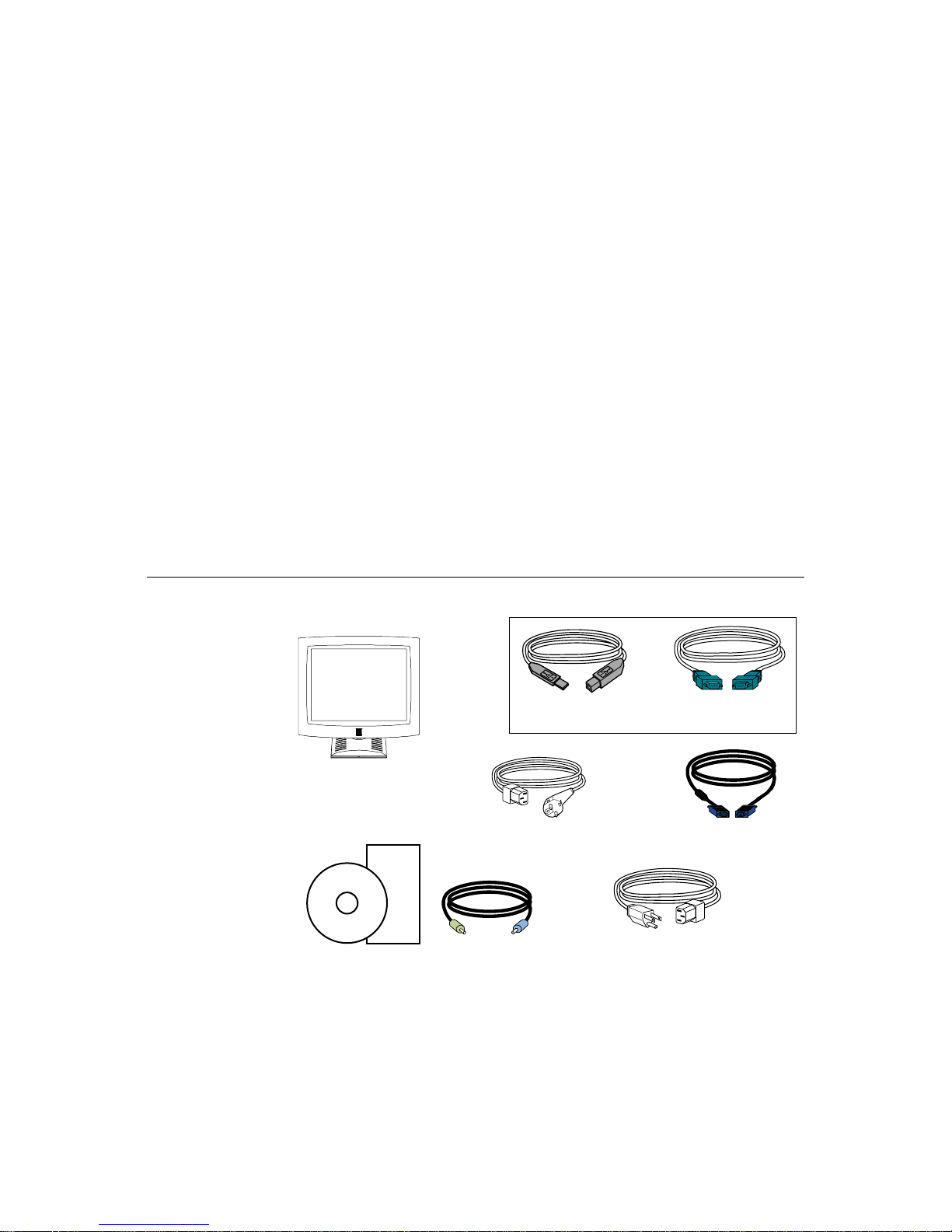
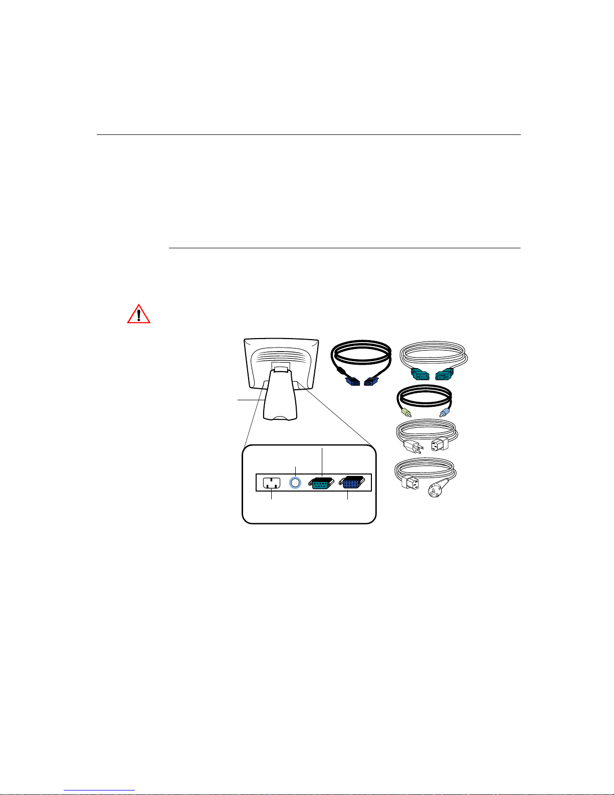
Unpac king Your Touchm onitor
Check that the following 8 items are present and in good condition:
C HAPTER
2
S
ETUP
cable
LCD Display
European monitor power cable
Quick Install Guide
CD
Software
Speaker Cable
User Guide-on CD,
Quick Install Guide and software CD
OR
Serial touchscreenUSB touchscreen
cable
Video cable
Speaker cable
Monitor power cable
(US/Canada)
2-3
Page 9
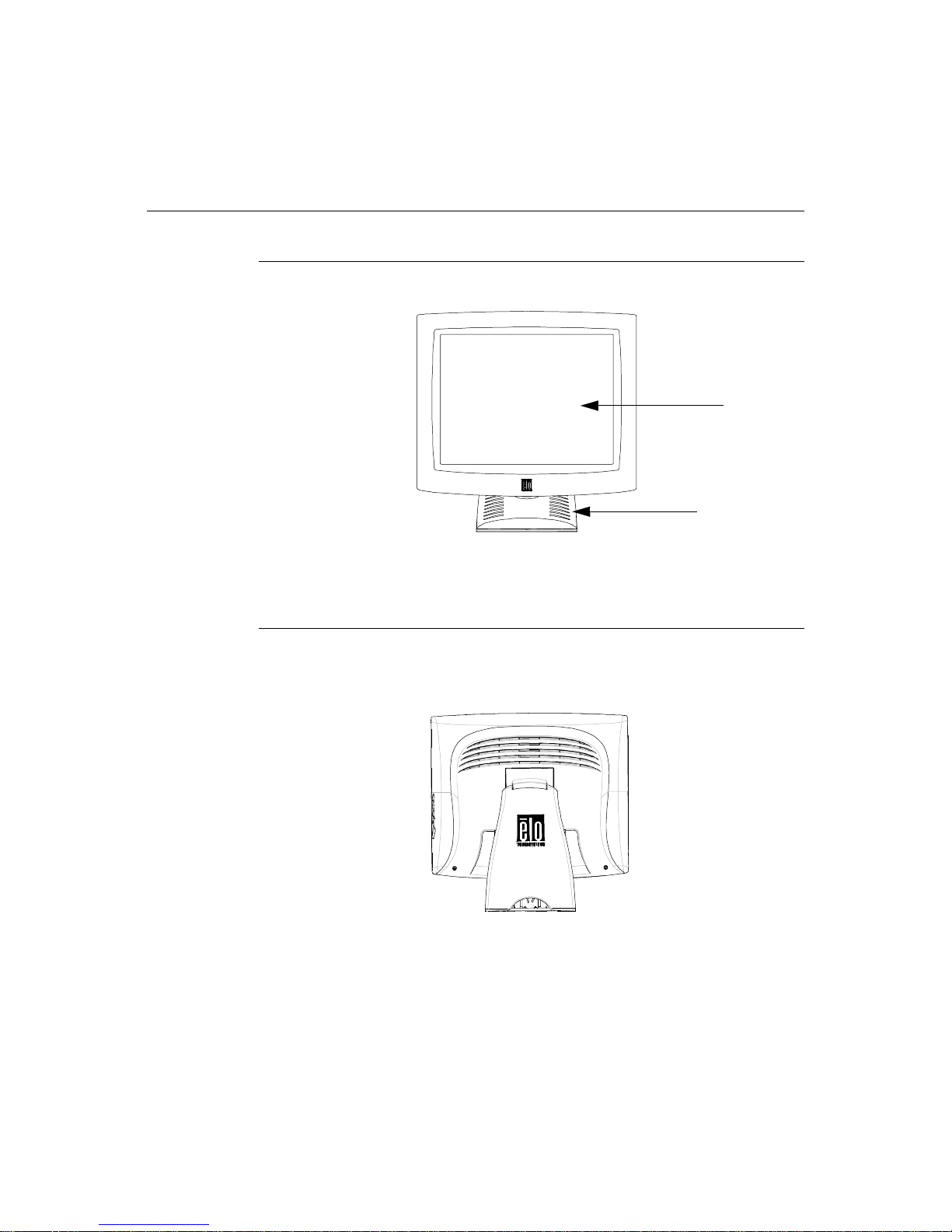
Prod uct O verview
Main Unit
Rear View
LCD Display
Stand
2-4 Elo Entuitive Touchmonitor User Guide
Page 10
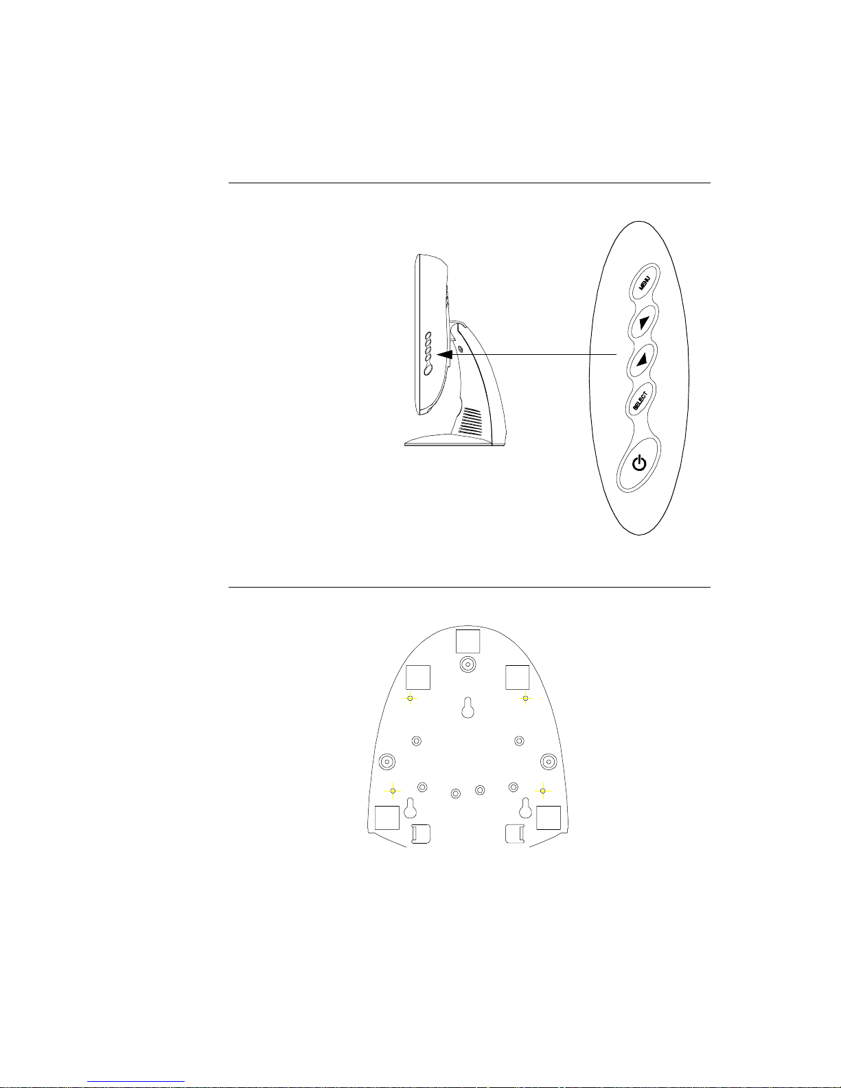
Side View
User Controls
Base Bottom View
2-5
Page 11
Touch Interface Connec tion
N
OTE
:
Your interface cables may have been pre-connected to your monitor at the factory.
Your touchmonitor comes with one of the following touc hscreen connector
cables: Serial (RS-232) cable or USB cable. (For Windows 98, 2000, Me and
XP systems only.)
To set up this display, please refer to the following figures and procedures:
Serial Connection
The following illustrat ions guide you step by step in connecting your
touchmonitor using a serial cable connec tion.
CAU TION
Before connecting the cables to your touchmonitor and PC, be sure that the computer
and the touchmonitor are turned off.
Serial touchscreen
cable
Removable back cover
Speaker
port
Power
Connections on underside
Video cable
Female 9-pin serial
Touchscreen
connector
Female 15-pin
video
connector
Speaker
cable
Monitor
power cable
(US/Canada)
European monitor
power cable
2-6 Elo Entuitive Touchmonitor User Guide
Page 12
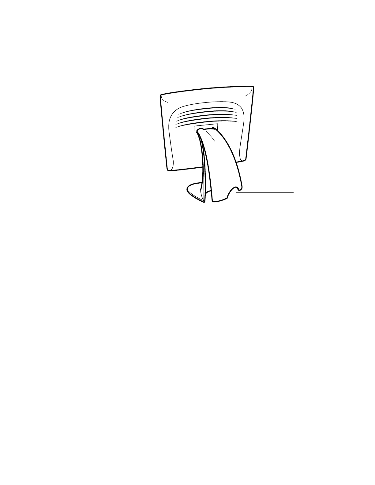
STEP 1-Removi ng the Back Cover
Bottom cut-out
• The cables are routed thro ugh the back of the stand.
• To remove the back cover, place one hand at the top of the stand an d your
other hand on the bottom cut-out.
• Pull forward from the bottom cut- out an d twist the cover until it snaps off.
The cable ports are located on the underside of your touchmonitor.
2-7
Page 13
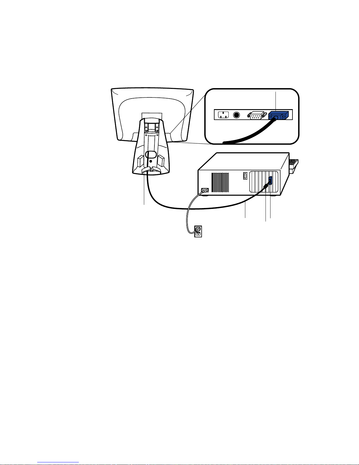
STEP 2-Connecting the Video Cable
Connections on underside
Female
video
connector
Cable management clip
Video
cable
Video
port
Ferrite bead
• Tilt the screen up and back to access the connection ports.
• Connect the 15-pin video cable (the ferrite bead end) to the video port on
your PC.
• Connect the other end of the video cable to the video connector on your
touchmonitor by routing the cable through the hole in the stand.
• Secure the cable to your touchmon itor and PC by turning the screws on the
connector clockwi se.
• Place the cable in the cable management clip.
2-8 Elo Entuitive Touchmonitor User Guide
Page 14
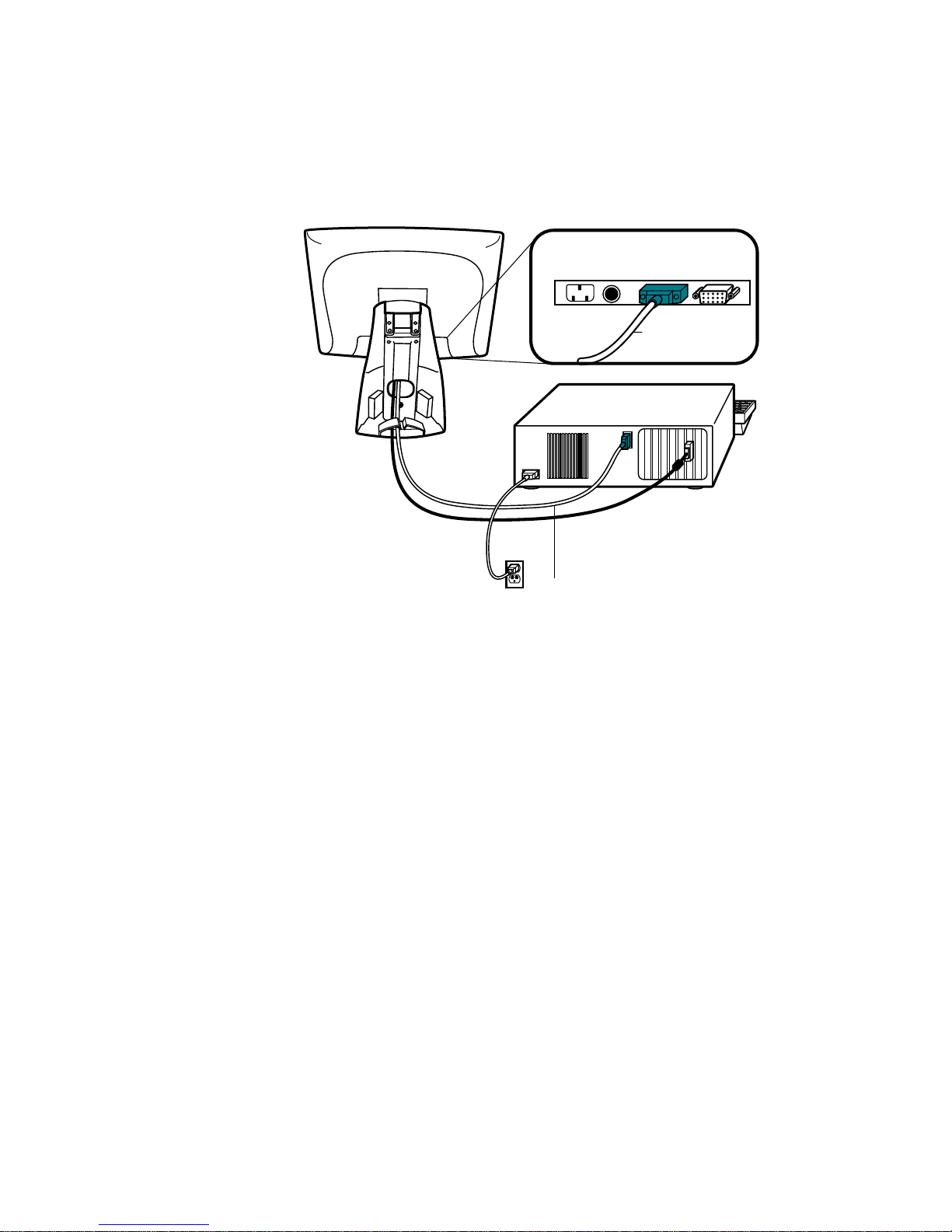
STEP 3-Connecting the S erial Touchscreen Cable
Connections on underside
Female 9-pin Serial
Touchscreen
connector
Serial
Touchscreen
cable
• Connect the female end of the serial (RS-232) cable to the serial port on the
back of your PC.
• Connect the male e nd of th e cable to t he s erial t ouchsc reen conne ctor on your
touchmonitor.
• Secure the cable to your touchmon itor and PC by turning the screws on the
connector.
• Route the cable through the cable management clip.
2-9
Page 15
N
STEP 4-Connecting the S peaker Cab le
OTE
:
If you do not wish to connect the speaker cable, go to step 5.
Speaker
cable
Connections on underside
Speaker port
• To use the built in speakers, you need to connect the speaker cable. Connect
the speaker cable to the speaker port inside the back of your touchmonitor.
• Connect the other end of the cable to the spe aker connector on your PC.
2-10 Elo Entuitive Touchmonitor User Guide
Page 16
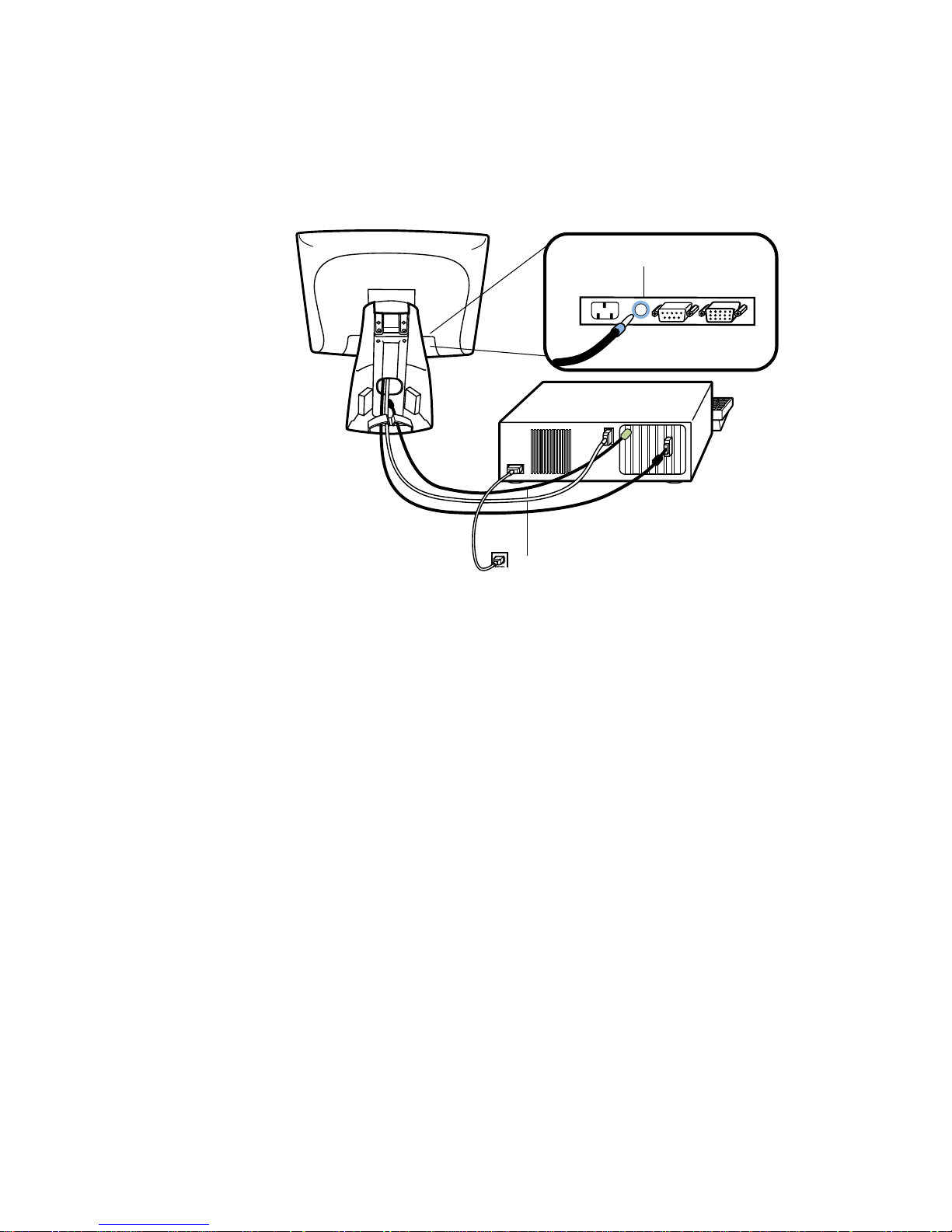
STEP 5-Connecting the Power Cable
Connections on underside
AC power cable port
Cable management clip
Power cable
Depending on where you live, you will use either the European or US/Canadian
power cable.
• Connect the female end of the power cable to the power port on the
touchmonitor.
N
• Route the cable through the cable management clip.
OTE
:
To protect your equipment against risk of damage from electrical surges in the power
line, plug the touchmonitor’s power cord into a surge protector, and then connect the
surge protector to a grounded AC electrical outlet.
STEP 6-Replacing the Back Cover
When all the cables hav e been co nne ct ed:
• Replace the b ack sta nd co v er.
• Power on your PC then your touchmonitor. After a brief pause the picture
should appear.
2-11
Page 17
N
OTE
CAUT ION
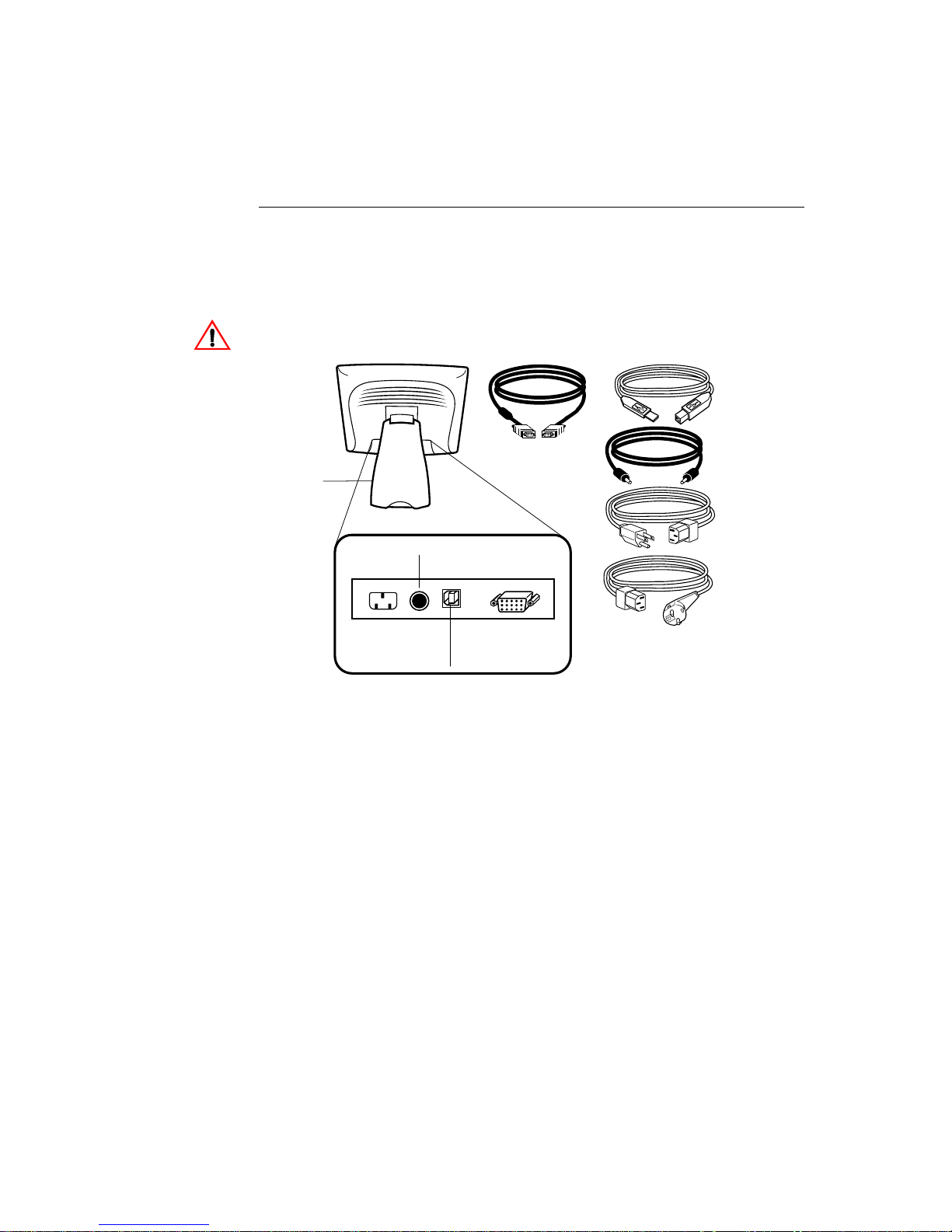
USB Connection
:
A USB connection can only be used if your PC is running Windows 98, 2000, Me or XP.
The following illust rations guide you step by step in connecting your
touchmonitor using a USB cable connection.
Before connecting the cables to your touchmonitor and PC, be sure that the computer
and the touchmonitor are turned off.
USB touchscreen
cable
Removable
back cover
Speaker port
Connections on underside
USB port
Video cable
Female 15-pin
video
connector
Speaker cable
Monitor
power cable
(US/Canada)
European monitor
power cable
2-12 Elo Entuitive Touchmonitor User Guide
Page 18

STEP 1-Removi ng the Back Cover
Bottom cut-out
• The cables are routed thro ugh the back of the stand.
• To remove the back cover, place one hand at the top of the stand an d your
other hand on the bottom cut-out.
• Pull forward from the bottom cut- out an d twist the cover until it snaps off.
The cable ports are located on the underside of your touchmonitor.
2-13
Page 19

STEP 2-Connecting the Video Cable
Connections on underside
Female 15-pin
Cable management clip
Video
cable
video
connector
Video
port
Ferrite bead
• Tilt the screen up and back to access the connection ports.
• Connect the 15-pin video cable (the ferrite bead end) to the video port on
your PC.
• Connect the other end of the video cable to the video connector on your
touchmonitor by routing the cable through the hole in the stand.
• Secure the cable to your touchmon itor and PC by turning the screws on the
connector clockwi se.
• Place the cable in the cable management clip.
2-14 Elo Entuitive Touchmonitor User Guide
Page 20

STEP 3-Connecting the U SB Touchscreen Cable
Connections on underside
USB
touchscreen
connector
Cable management clip
USB
touchscreen
cable
• Connect the USB t ouchscree n cabl e to the US B touch screen co nnector on the
touchmonitor.
• Connect the other end of the USB touchscreen cable to your PC.
• The touchscreen cabl e connector s should fit snugly into the connectors on
your touchmonitor and PC.
• Route the cable through the cable management clip.
2-15
Page 21

STEP 4-Connecting the S peaker Cab le
Speaker cable
Connections on underside
Speaker port
N
OTE
:
If you do not wish to connect the speaker cable, go to step 5.
• To use the b uilt in s peake rs, you need to connect t he speaker c able. B oth ends
of the speaker cable are identical, so you can connect either end of the
speaker cable to the speaker port inside the stand of your touchmonitor.
• Connect the other end of the cable to the spe aker connector on your PC.
2-16 Elo Entuitive Touchmonitor User Guide
Page 22

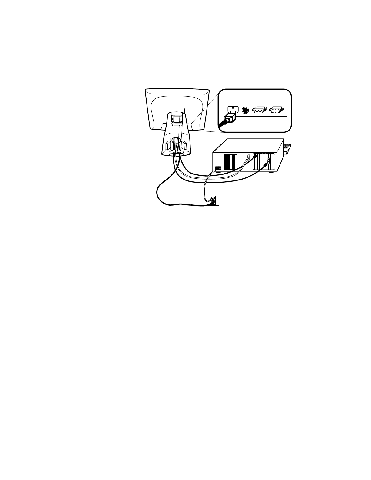
STEP 5-Connecting the Power Cable
Connections on underside
Power cable
Depending on where you live, you will use either the European or US/Canadian
power cable.
N
• Connect the female end of the power cable into the power port on the
touchmonitor.
• Route the cable through the cable management clip.
OTE
:
To protect your equipment against risk of damage from electrical surges in the power
line, plug the touchmonitor’s power cord into a surge protector, and then connect the
surge protector to a grounded AC electrical outlet.
STEP 6-Replacing the Back Cover
When all the cables hav e been co nne ct ed:
• Put the back stand cover on.
• Power on your PC then your touchmonitor. After a brief pause the picture
should appear.
2-17
Page 23

Optimizing the LCD Display
To ensure the LCD display works well with your compute r, configure the
display mode of your graphic card to make it less than or equal to 1024 x 768
resolution, and make sure the timing of the display mode is c ompatible with the
LCD display. Refer to Appendix A for more information about resolution.
Compatible video modes for your touchmonitor are listed in Appendix C.
VESA M ou nt on Your Touchmon itor
Your touchmonitor confo rms to the VESA Flat Panel Monitor Physical
Mounting Interface (FPMPMI™) Standard which defines a physical mounting
interface for flat panel monitors, and corresponding standards for flat panel
monitor mounting device s, suc h as wall and table arms. The VESA mounting
interface is loca ted on the back of your touchmonitor and is shipped
pre-connected to the base.
M4x0.7
threaded holes
VESA mounting
interface
N
OTE
:
The abov e drawing displays the VESA mounting interfac e aft er the removal of the
mounting cover and base.
2-18 Elo Entuitive Touchmonitor User Guide
Page 24

N
Accessing the VESA Mounting Interface
If you want to convert your desktop monitor to a wall mount or kiosk monitor,
follow the steps below to acces s the VESA mounting interface.
OTE
:
You will need a screwdriver for the fol lowing steps.
1 Remove the back cover of the stand by pulling forward on the bottom
cut-out.
2 Carefully lay the monitor face down. At the top of th e mounting screw cover
there are two slots. With a screwdriver, pry open the mounting screw cover.
The cover fit is tight so remove it carefully.
3 When you remove the mounting screw cover, you will see four screws.
Remove the screws to mount your monitor. Refer to the drawing on page 18.
The following companies provide VESA mounting devices compatible with
your touchmonitor:
Ergotron
800-888-8458
651-681-7600
www.ergotron.com
GCX
800-228-2555
707-773-1100
www.gcx.com
Mounting the B ase
You can also mount your touc hmonitor by using the keyholes in the base of the
stand. These keyholes provide easy slide on mounting. You can also bolt your
touchmonitor to a table top or other flat surface. Please refer to Appendix C for
location and dimension of the mounting holes.
Innovative Office Products
800-524-2744
610-253-9554
www.innov-office-prod.com
MRI
800-688-2414
www.mediarecovery.com
2-19
Page 25

Installing the D river Soft ware
Elo TouchSystems provides driver software that allows your touchmonitor to
work with your computer. Drivers are located on the enclosed CD-ROM for the
following operat ing systems:
• Windows 2000
• Windows Me
• Windows 98
• Windows 95
• Windows NT 4.0
Additional driver s and driver information fo r other operating systems (i ncluding
MS DOS, Windows 3.x, OS/2, Macintosh and Linux) are available on the Elo
TouchSystems web site at www.elotouch.com.
Your Elo touchmonitor is plug-a nd-play compliant. Information on the video
capabilitie s of your touchmonitor is sent to your video display adapter when
Windows starts. If Windows detects your touchmonitor, follow the instruc tions
on the screen to install a generic plug-and-play monitor.
Refer to the appropriat e following section for driver installa tion instructions.
2-20 Elo Entuitive Touchmonitor User Guide
Page 26

Installing the Serial Touch Driver
N
Inst a lling the Serial Touch Dr iv e r for
Windows 2000, Me,
95/98 and NT 4.0
OTE
:
For Win dows 2000 and NT 4.0 you must have administrator access rights to install the
driver.
1 Insert the Elo CD-ROM in your computer’s CD-ROM drive.
2 If the AutoStart feature for your CD-ROM drive is active, the system
automatically de tects the CD and starts the setup program.
3 Follow the directions on the screen to complete the driver setup for your
version of Windows.
4 If the AutoStart featu re is no t acti ve:
5 Click Start > Run.
6 Click the Browse button to locate the EloCd.exe program on the CD-ROM.
7 Click Open, then OK to run EloCd.exe.
8 Follow the directions on the screen to complete the driver setup for your
version of Windows.
2-21
Page 27

Inst a lling the Serial Touch Dr iv e r for M S-DOS and
Windows 3. 1
You must have a DOS mouse driver (MOUSE.COM) installed for your mouse
if you wish to continue using your mouse along with your touchmonitor in
DOS.
To install Windows 3.x and MS-DOS from Windows 95/98, follow the
dire c t io ns be lo w:
1 Insert the Elo CD-ROM in your computer’s CD-ROM drive.
2 From DOS, type d:\EloDos_W31 to change to the correct directory on the
CD-ROM (your CD-ROM drive may be mapped to a different drive letter).
3 Type install and press Enter to start the installation.
4 Align the touchscree n.
You must have already completed Steps 1 and 2 before proceeding. Refer to
Chapter 2 of the Elo DOS and Windows Driver Guide as necessary for
additional ins tallation information.
To run the INSTALL program:
1 Type INSTALL at the DOS prompt in the directory containing the driver
inst a l l f i l e s .
2 INSTALL asks you to select the softwar e to install. Then choose
d:\EloDos_W31 from the displ ayed list.
3 INSTALL also asks you for the paths to use during ins tallation, or you may
use its defaults. INSTALL creates directories as necessary, and warns you if
they exist.
If you are updating your softwar e, you may wish to specify the paths conta ining
the earlier versi ons, and overwrite the obsolete files. All executa ble programs
are upward comp a tib le. Fo r a list of differences from each prev iou s ve rsion of
the drivers, be sure to select "Differences from Previous Versions" during the
installation process.
INSTALL updates your AUTOEXEC.BAT file with the drivers you select.
INSTALL makes a copy of your original AUTOEXEC.BAT file, cal led
AUTOEXEC.OLD. If you already have Elo driver commands in your
AUTOEXEC.BAT file, they will be commented out.
When INSTALL is finished, it leaves a file called GO.BAT in the subdirectory
you specified. GO loads the touchscreen driver, runs the calibration program
ELOCALIB, and gives you some final instructions.
If you are using Windows 3.1, you will also calibrate the touchscreen within
Windows 3.1 with the Touchscreen Control Panel.
2-22 Elo Entuitive Touchmonitor User Guide
Page 28

N
Installing the USB T ouch Driver
Installing the USB T ouch Driver for Windows 2000, Me
and 98
1 Insert the Elo CD-ROM in your computer’s CD-ROM drive.
If Windows 98, Windows Me or Windows 2000 starts the Add New
Hardware Wizard:
2 Choose Next. Select “Search for the best driver for your device
(Recommended)” and choose Next.
3 When a list of search locations is displayed, place a checkmark on “Specify a
location” and use Browse to select the \EloUSB directory on the Elo
CD-ROM.
4 Choose Next. Once the El o TouchSystems USB touchscreen driver has been
detected, choose Next agai n.
5 You will see several files being copied. Insert your Windows 98 CD if
prompted. Choose Finish.
If Windows 98, Windows Me or Windows 2000 does not start the Add New
Hardware Wizard:
OTE
:
For Win dows 2000 you must have administrat or access rights to install the driv er.
1 Insert the Elo CD-ROM in your computer’s CD-ROM drive.
If the AutoStart feature for your CD-ROM drive is active, the system
automatically de tects the CD and starts the setup program.
2 Follow the directions on the screen to complete the driver setup for your
version of Windows.
If the AutoStart featu re is no t acti ve:
1 Click Start > Run.
2 Click the Browse button to locate the EloCd.exe program on the CD-ROM.
3 Click Open, then OK to run EloCd.exe.
4 Follow the directions on the screen to complete the driver setup for your
version of Windows.
2-23
Page 29

2-24 Elo Entuitive Touchmonitor User Guide
Page 30

About T ouchmonitor Adjustments
Your touchmonitor will unlikely require adjustment. Variations in video output
and application may requi re adjustments to your touchmonitor to optimize the
quality of the displa y.
For best performance, your touchmonitor should be operating in native
resolution, that is 1024 x 768 at 60-75 Hz. Use the Display control panel in
Windows to choose 1024 x 768 resolution.
C HAPTER
3
C
HAPTER
3
O
PERATION
Operating in other resolutions will degrade video performance . For further
information, please refer to Appendix A.
All adjustments you make to the controls are automatically memorized. This
feature saves you from having to rese t your choices every time you unplug or
power your touchmonitor off and on. If there is a power failure your
touchmonitor settings will not default to the factory specifications.
Using the On- Screen Displa y (OSD) M enus
All adjustments are made by using the on-screen display (OSD) menus. All
menu items can be selected by using the buttons on the side bezel.
N
OTE
:
OSD menu default is enabled.
3-25
Page 31

Side Be zel Butt ons
MENU
1
2
3
SELECT
4
1
2
3
4
5
Contro l Function
Menu Display on ex it the OSD menus.
Contrast/
Up/Toggle
Volume/Down
Toggle
Enter Select item
1. Shortcut to Contrast adjustment
2. Increase value of adjustment items
3. With menu on toggles OSD options
1. Shortcut to Volume adjustment
2. Decrease value of the adjustment items
3. With menu on toggles OSD options
1. Shortcut to Auto Adjust
2. Select- To select the adjustment items from the
OSD menus.
3. Auto- To act ivate the “Aut o A d justment”
function to obtain an optimum im age.
5
3-26 Elo Entuitive Touchmonitor User Guide
Power Switch Switches the power on/off to your touchmonitor.
Enable/ D isable 1. Press th e U p and Down button s at the same
time to ena ble /d is abl e the MU TE f unc ti ons . OS D
menu default is enabled
2. Press the Me nu and Up buttons at the same
time and hold for two seconds to enable/disable
the OSD functions. OSD menu default is
enabled.
3. Press the Me nu and Down buttons at the same
time and hold for two seconds to enable/disable
the power loc k function. OSD menu default is
enabled.
Page 32

OSD M enu F unction
CONTRAST
50
Contrast
Controls the picture con trast
Brightness
Controls the picture brigh tness
V-Position
Controls the vertical position
H-Position
Controls the horizontal position
Recall De faults
Recalls f actory settings of the image
parameters
C1/C2/USER (Color)
Using these icons, you can select one of
the preset color temperatures (9300°K or
6500°K). Confirm your choice by
pres si ng the SELECT button. If you
want to change the color tem perature s
indiv idu al ly, se le ct U SER an d c onf ir m b y
pressing the OSD button SELECT. Now
you can use the OSD dial to toggle
between the settings R, G and B (red,
green and bl ue foreground). To change a
setting, first press the SELECT button,
then ch oo s e the desired value w ith the
OSD di al . To confir m th e setting, press
the SELECT button again.
If you don’t need to adjust any further
settings, choose the
icon to return to the OSD main menu.
Phase
Controls the vertical fine adjustment
Clock
Controls the horizontal fine adjustment
OSD H-Position
Adjusts the horizontal position of the OSD
menu
OSD V-Position
Adjust th e vertical posi tion of the OSD menu
OSD Time
Determines how long (in seconds) the OSD
menu waits befor e cl osing au to m a tic a lly after
no action has been performed.
Auto Adjus t
Autom at ic a lly selects th e o ptional set tings for
image parameters (brightness, contrast, image
position, phase, etc. )
OSD Language
Selection of the OSD menu language: English,
French, Ge rm an, Spanish , Japanese.
Image Inform ation
Display s the current graphics mode.
3-27
Page 33

3-28 Elo Entuitive Touchmonitor User Guide
Page 34

If you are experiencing trouble with your touchmonitor, refer to the following
table. If the problem persists, please contact your local dealer or our service
center.
Solutions to Common Problems
Problem Suggestion(s)
C HAPTER
4
C
HAPTER
4
T
ROUBLESHOOTING
No image ap pears on screen. Check that al l the I/O and power connectors are properly
connected as described in Chapt er 2.
Make sure the pins of the connectors are not crooked or
broken.
Test power su pply by trying diff erent cables, a different
wall outlet or plug another appliance into the outlet.
Make certa in the vi deo cab le is prope rl y conne ct ed a nd tha t
it is not damaged. Check for bent pi ns on the cable
connectors.
Ensure that your computer and video card are properly
configured. (Consult vide o card documentation.)
“Out of Range ” display Check to see if the resolution of your computer i s higher
than that of the LCD display.
Reconfigure the resolution of your computer to make it less
than or equal to 1024 x 768. See Appendix A for more
info rmation on res olution .
4-29
Page 35

Image has vertical flickering line bar s. Use “PHASE” to make an ad justment.
Check and reco nfigure the display mode of the vertical
refresh ra te of y our gr aph ic car d t o mak e it co mpat ib le with
the LCD display.
Image is uns table and flickering Use “CLOC K” to m ake an adjustment.
Image is scrolling Make sure the VGA signal cable (or adapter) is well
connected.
Check and reco nfigure the display mode of the vertical
refresh ra te of y our gr aph ic car d t o mak e it co mpat ib le with
the LCD display.
Touch doesn’t work Make sure cable is securely attached at both ends.
4-30 Elo Entuitive Touchmonitor User Guide
Page 36

A PPENDIX
A
C
HAPTER
4
N
ATIVE
The native resolution of a monitor is the resolution level at which the LCD
panel is designed to perfor m best. For the Elo LCD touchmonitor, the native
resolution is 1024 x 768 for the XGA-15 inch siz e. In almost all cases, screen
images look best when viewed at their native resolution. You can lower the
resolution setting of a monitor but not increase it.
Input Video 15" LCD
640x480 (VGA) Transfor ms input format to 1024x768
800x600 (SVGA) Transforms input format to 1024x768
1024x768 (XGA) Displays in Native Resolution
R
ESOLUTION
The native resolution of an LCD is the actual number of pixels horizontally in
the LCD by the number of pixels vertical ly in the LCD. LCD resol ution is
usually represented by the following symbols:
VGA
SVGA
XGA
SXGA
UXGA
640x480
800x600
1024x768
1280x1024
1600x1200
A-31
Page 37

As an example, a SVGA resolution LCD panel has 800 pixels horizontally by
600 pixels vertically. Input video is also represented by the same terms. XGA
input video has a format of 1024 pixels hor iz ontally by 768 pixels vertically.
When the input pixels containe d in the video input format match the native
resolution of the pa nel, there i s a one to one corre spondence of mapping of input
video pixels to LCD pixels. As an example, the pixel in column 45 and row 26
of the input video is in column 45 and row 26 of the LCD. For the case when
the input vide o is a t a lowe r res oluti on than t he nat ive res oluti on of th e LCD, the
direct corresponde nce between the video pixels and the LCD pixels is lost. The
LCD controller c an compu te the correspon dence be tween video pi xels a nd LCD
pixels using algorithms contained on its controller. The accuracy of the
algorithms determines the fidelity of conversion of video pixels to LCD pixels.
Poor fideli ty conversion can result in artifacts in the LCD displayed image such
as varying width charact ers.
A-32 Elo Entuitive Touchmonitor User Guide
Page 38

A PPENDIX
B
C
HAPTER
4
T
OUC HMON ITOR
This manual contains inf ormation that is important for the proper setup and
maintenance of your touc hmonitor. Befor e setti ng u p and poweri ng on your new
touchmonitor, read thr ough this manual, especia lly Chapter 2 (Insta llati on), and
Chapter 3 (Ope rati o n).
1 To reduce the risk of electric shock, follow all safety notices and never open
the touchmonitor case.
2 Turn off the product before cleaning
S
AFET Y
3 Your new touchmonitor is equipped with a 3-wire, grounding power cord.
The power cord plug will onl y fit into a grounde d outlet. Do not a ttempt to fit
the plug into an outlet that has not been confi gured for this purpose. Do not
use a damaged power cord. Use only the power cord that comes with your
Elo TouchSystems Touchmonitor. Use of an unauthorized power cord may
invalidate your warranty.
4 The slots located on the sides and top of the touchmo nitor case are for
ventilatio n. Do not bloc k or insert anything inside the ventilation slots.
5 It is important that your touchmonitor remains dry. Do not pour liquid int o or
onto your touchmonitor . If your touchmo nitor becomes wet do not attempt to
repair it yourself.
B-33
Page 39

Care an d Handling of Your Touchm onitor
The following tips will help keep your Elo Entuitive touchmonitor function ing
at the optimal level.
• To avoid risk of electric shock, do not disassemble the brick supply or
display unit cabine t. The unit is not user serviceable. Remember to unplug
the display unit from the power outlet before cleaning.
• Do not use alcohol (methyl, ethyl or isopropyl) or any strong dissolvent. Do
not use thinner or benzene, abra sive cleaners or compressed air.
• To clean the display unit cabinet , use a cloth lightly dampened with a mild
detergent.
• Avoid getting liquids inside your touchmonitor. If liquid does get inside,
have a qualified servi ce te chnician check it before you power it on again.
• Do not wipe the screen with a cloth or sponge that could scratch the surface.
• To clean the touchscreen, use window or glass cleaner. Put the cleaner on the
rag and wipe the touchscreen . Never apply the cleaner directly on the
touchscreen
B-34 Elo Entuitive Touchmonitor User Guide
Page 40

A PPENDIX
C
C
HAPTER
4
T
ECHNICAL
Compatib le Video Modes
Your Elo Entuitive touchmon itor is compatible with the following standar d
video modes:
Mode Resolution H. Frequency (kHz) V. Frequency (Hz)
IBM & VESA VGA 640 x 350 31.47 70.09
IBM & VESA VGA 640 x 400 31.47 70.09
IBM & VESA VGA 720 x 400 31.47 70.09
IBM & VESA VGA 640 x 480 31.47 59.94
IBM & VESA VGA 640 x 480 37.86 72.81
IBM & VESA VGA 640 x 480 37.50 75.00
VESA SVGA 800 x 600 35.16 56.25
VESA SVGA 800 x 600 37.88 60.32
VESA SVGA 800 x 600 48.08 72.19
VESA SVGA 800 x 600 46.88 75.00
VESA XGA 1024 x 768 48.36 60.00
VESA XGA 1024 x 768 56.48 70.07
VESA XGA 1024 x 768 60.02 75.03
Apple Macintosh LC 13” 640 x 480 34.97 66.61
Apple Macintosh II 13” 640 x 480 35.00 66.67
Apple Macintosh 16” 832 x 624 49.73 74.55
Apple Macintosh 19” 1024 x 768 60.24 75.02
NEC FC-98 series 640 x 400 24.83 56.42
NEC FC-98 series 640 x 400 31.47 70.01
NEC FC-98 series 640 x 480 31.47 59.94
S
PECIFICATIONS
C-35
Page 41

Touchmo nitor Specificat ions
Table C.1
15" LCD Touchmonitor (ET1 5-XXWA-1) Specifications
Display Type
Size
Pixel Format
Touchscreen
Colors
Display
Active matrix, thin film transistor
(TFT) , liquid crystal display
15-inch diagonal
304.1 x 228.1 m m useful screen
area
1024 x 768
0.125-inch IntelliTo uch and
AccuTouch, anti-glare
Intelli Touch or AccuTouch
16 million with dithering
IntelliTouch: 270 cd/m² typical AccuTouch: 250 cd/m² typical
Brightness
Back-light Lamp
Life
Viewing Ang le
Contrast Ratio
Display R esponse
25,000 hou rs at 50% brightness
typical
Horizontal
Vertical
450:1 typical
13 ms (tr) /2 7 ms (tf)
Time
Environmental
Mechanical
Electrical
Speak ers
Agencies
Operating Temp
Storage Temp
Humidity
Weight
Size
Input Video
Input Power
Power Dissipation
8 ohms, 1 watt per speaker
Safety & EMC UL, cUL and TUV-GS, FCC-B,
±65 or 12 0 de gree s total
±60- 45 or 105 deg re es tota l
0°C to 40°C
-25°C to +60°C
80% non-condensing AT
95% IT
17 lbs. maximum approx. weight
for IntelliTouc h an d A cc u T ou c h
See drawings on next page.
VGA/SVGA/XGA analog video
100-240 VAC, 50/60 Hz.
Universal
CE, C-Tick and VCCI
C-36 Elo Entuitive Touchmonitor User Guide
Page 42

Table B.1
IntelliTouch Touchmonitor Specifications
Mechanical
Positional Accuracy
Touchpoint Densit y
Touch Activation
Standard deviation of err or is less than 0.080 in. (2.03 mm).
Equate s to les s th an ± 1%.
More than 100,000 touchpoints/in2 (15,500 touchpoints/cm2).
Typically less than 3 ounce s (85 grams).
Force
Surface Durability
Expected Life
Performance
Sealin g
Surfac e durability is that of glass, Mohs’ hardness rating of 7.
No know n we ar -o ut mech an ism, as th ere are no layers, coating s,
or moving pa rts. IntelliT ouch technology has been operationally
tested to more than 5 0 million to uches in on e location without
failure, using a stylus similar to a finger.
Unit is sealed to protect against splas hed liquids, di rt, and dust.
Optical
Light Transmission
90%
(per ASTM D1003)
Visual Resolution
Gloss (per ASTM
D2457 using a 60degree gloss meter)
All measurem ents made using USA F 1951 Resolution Char t,
under 30X magnificatio n, with test unit located approximately
1.5 in (38 mm) from surface of resolution chart.
Clear surface: Excellent, with no noticeable degradation.
Antiglare surface: 6:1 minimum.
Antiglare surface: Curved: 60 ± 20 gloss unit s or 75 ± 15 gloss
units.
C-37
Page 43

Environmental
Chemical Resistance
Electrostatic
Protection (per EN 61
000-4-2, 1995)
The acti ve area of the touchscreen is resistant to all chemicals
that do no t affect glass, such as:
Acetone
Toluene
Methyl et hyl ketone
Isopropyl alcohol
Methyl alcohol
Ethyl ac etate
Ammo ni a-bas ed gl ass clea n er s
Gasoline
Kerosene
Vinegar
Meets Level 4 (15 kV air/8 kV contact discharges).
C-38 Elo Entuitive Touchmonitor User Guide
Page 44

Table B.1
AccuTouch Touchmonitor Specifications
Mechanical
Construction
Positional Accuracy
Touchpoin t Den sit y
Touch Activatio n Force
Surface Durability
Expected Life
Performance
Optical
Light Transmis s ion
(per ASTM D1003)
Visual Resolution
Haze (per ASTM D1003)
Gloss (per ASTM D2457)
Top: Pol ye s te r w ith ou ts id e har d -s ur face coa tin g wi th cle ar or
antiglare finish.
Inside : Transparent conductive co ating.
Bottom: G lass substrate with uniform resistive coating. Top and
bottom la yers separated by Elo-patente d separator dots.
Standard deviation of error is less than 0.080 in. (2.03 mm). This
equates to less than ±1%.
More than 100,000 touchpoints/in² (15,500 touchpoints/ cm ²).
Typically less than 4 ounces (113 grams).
Meets Taber Abrasion Test (ASTM D1044), CS-10F wheel, 500 g.
Meets pencil hardness 3H.
AccuTouch technology has been operationally tested to greater than
35 million touches in one location without failure, using a stylus
similar to a finger.
Typically 75% at 550-nm wavelength (visible light spectrum).
All measurements made using USAF 1951 Resolution Chart, under
30 X magnification, with test unit located approximately 1.5 in. (38
mm) from su rface of reso lution chart.
Antiglare surface: 6:1 minimum.
Antiglare surface: Less than 15%.
Antiglare surface: 90 ± 20 gloss units tested on a hard-coated front
surface.
C-39
Page 45

15" LCD Touc hmon itor (ET15-X XWA-1) Dimensio ns
C-40 Elo Entuitive Touchmonitor User Guide
Page 46

See Detail A
Detail A
C-41
Page 47

C-42 Elo Entuitive Touchmonitor User Guide
Page 48

C
HAPTER
4
R
EGULATORY INFORMATION
I. Electrical Safety In fo r mation:
A) Compliance is required with respect to the voltage, frequency, and current
requirements indicated on the manufacturer’s label. Connection to a different
power source than those specified herein will likely result in improper operation,
damage to the equipment or pose a fire hazard if th e limitations are not follow ed.
B) There are no operator serviceable parts inside this equipm ent. There are hazardous vol tages generated by this equipment whic h constitute a safety hazard. Service
should be provided only b y a qualified service technic ian.
C) This equipment is provided with a detach able power cord which has an in tegral
safety ground wire intended for connection to a grounded safety outlet.
1) Do not substi tute the cord with othe r than the provide d approved typ e.
Under no circumstances use an adapter plug to connect to a 2-wire outlet as
this will defeat the continuity of the grounding wire.
2) The equipment requires the use of the ground wire as a part of the safety
certification, modification or misuse can provide a shock hazard that can
result in serious injury or death.
3) Contact a qualified electrician or the manufacturer if there are questions
about the installa tion prior to connecting the equipment to mains power.
II. Emissions and Immunity Information
A) Notice to Users in the United States: This equipment has been tested and found
to comply with the limits for a Class B digital device, pursuant to Part 15 of FCC
Rules. These limits are designed to provide reasonable protection against harmful
interference in a residential installation. This equipment generates, uses, and can
radiate radio frequency energy, and if not installed and used in accordance with the
instructions, may cause harmful interference to radio com munications.
B) Noti ce to Users in Canada: This equipment co m p lies with the Class B limits for
radio noise emissions from digital apparatus as established by the Radio Interference Regulations of Industrie Canada.
C) Notic e to U se rs in th e E ur o pe an Unio n: Us e only the prov id ed power cords and
interconnecting cabling provided with the equipment. Substitution of provided
cords and cabling may compromise electrical safety or CE Mark Certification for
emission s or immunity as re quired by the following standards:
43
Page 49

This Inform ation Technology Equipment (ITE) is required to have a CE Mark
on the manufacturer’s label which means that the equipment has been tested
to the following Directives and Standards:
This equipment has been tested to the requirements for the CE Mark as
required by EMC Directive 89/336/EEC indicated in European Standard EN
55 022 Class B and the Low Voltage Directive 73/23/EEC as indicated in
European Standard EN 60 950.
D) General Information to all Users: This equipment generates, uses and can radiate radio frequency energy. If not installed and used according to this manual the
equipment may cause interference with radio and television communications.
There is, however, no guarantee that interference will not occur in any particular
instal lation due to site-specific factors.
1) In order to meet emission and immunity requirements, the user must
observe the following:
a) Use only the provided I/O cables to connect this digital device with
any computer.
b) To ensur e compliance, use only the provided manufacturer’s approv ed
line cord.
c) The user is cautioned that changes or modifications to the equipment
not expressly approved by the party responsible for compliance could
void the user’s authority to operate the equipment.
2) If this e quipment appear s to cause interference with radio or television
reception, or any other device:
a) Verify as an emission sou rce by turning the equipment off and on.
b) If you de te r m in e th a t th is equ i pm e n t is cau s in g the int er fe rence, tr y to
correct the interferenc e by using one or more of the follow ing measures:
i) Move the digital device away from the aff ected receiver.
ii) Reposition (turn) the digital device with respect to the affected
receiver.
iii) Reorient the affected receiver’s antenna.
iv) Plug the digital device into a different AC outlet so the digital
device and the receiver are on different branch circuits.
v) Disconnect and remove any I/O cables that the digital device
does not use. (Unterminated I/O cables are a potential source of
high RF emission levels.)
vi) Plug the digital device into only a grounded outlet receptacle.
Do not use AC adapter plugs. (Removing or cutting the line cord
ground may increase RF emission levels and may also present a
lethal shock hazard to the user.)
If you need additional help, consult your dealer, manufacturer, or an experienced radio or televisi on technician.
44 Elo Entuitive Touchmonitor User Guide
Page 50

N10051
45
Page 51

46 Elo Entuitive Touchmonitor User Guide
Page 52

C
HAPTER
4
W
ARRANTY
Except as otherwise stated herein or in an order acknowledgment delivered to
Buyer, Seller warrants to Buyer that the Product shall be free of defects in
materials and workmanship. The warranty for the touchmonitors and
components of th e product are: 3 years monitor, 10 years IntelliTouch screen, 5
years Accu- Touch screen, 5 years Cont roller.
Seller makes no warranty regarding the model life of components. Seller’s
suppliers may at any time and from time to time make changes in the
components deliver ed as Products or components.
Buyer shall notify Seller in writing promptly (and in no case later than thirty
(30) days after discov ery) of the failure of any Product to conform to the
warranty set forth above; shall describe in commercially reasonable detail in
such notice the symptoms assoc iated with such failure; and shall provide to
Seller the opportun ity to inspect such Products as installed, if possible. The
notice must be received by Seller during the Warranty Period for such product,
unless otherwise directed in writing by the Seller. Within thirty (30) days after
submitting such noti ce, Bu yer shall package the allegedly defective Produc t in
its original ship ping carton(s) or a functional equivalent and shall ship to Seller
at Buyer’s expense and risk.
Within a reasonable time after receipt of the allegedly defective Produc t and
verification by Seller that the Product fails to meet the warranty set forth above,
Seller shall corr ect such failure by, at Seller’s options, eit her (i) modifying or
repairing t he Product or (ii) replacing the Product. Such modifica tion, repair, or
replacement and the return shipment of the Product with minimum insurance to
Buyer shall be at Se ller’s expense. Buye r shall be ar the r isk of loss or damage in
transit, and may insure the Product. Buyer shall reimburse Seller for
transportat ion cost incurred for Product returned but not found by Seller to be
defective. Modifi cati on or repair, of Products may, at Seller’ s option , take place
either at Seller ’s facilities or at Buyer’s premises. If Seller is unable to modify,
repair, or replace a Product to conform to the warranty set forth above, then
Seller shall, at Seller’s option, either refund to Buyer or credit to Buyer’s
account the purchase price of the Product less depreciation calculated on a
straight-line basis over Seller’s stated Warranty Period.
47
Page 53

THESE REMEDIES SHALL BE THE BUYER’S EXCLUSIVE REMEDIES
FOR BRE ACH OF WARRANTY. EXCEPT FOR THE EXPRESS
WARRANTY SET FORTH ABOVE, SELLER GRANTS NO OTHER
WARRANTIES, EXPRESS OR IMPLIED BY STATUTE OR OTHERWISE,
REGARDING THE PRODUCTS, THEIR FITNESS FOR ANY PURPOSE,
THEIR QUALITY, THEIR MERCHANTABILITY, THEIR
NONINFRINGEMENT, OR OTHERWISE. NO EMPLOYEE OF SELLER
OR ANY OTHER PARTY IS AUTHORIZED TO MAKE ANY WARRANTY
FOR THE GOODS OTHER THAN THE WARRANTY SET FORTH
HEREIN. SELLER’S LIABILITY UNDER THE WARRANTY SHALL BE
LIMITED TO A REFUND OF THE PURCHASE PRICE OF THE PR ODUCT.
IN NO EVENT SHALL SELLER BE LIABLE FOR THE COST OF
PROCUREMENT OR INSTALLATION OF SUBSTITUTE GOODS BY
BUYER OR FOR ANY SPECIAL, CONSEQUENTIAL, INDIRECT, OR
INCIDENTAL DAMAGES.
Buyer assumes the risk and agrees to indemnify Seller against and hold Seller
harmless from all liability relating to (i) assessing the suita bility for Buyer’s
intended use of the Product s and of any system design or drawing and (ii)
determining the complia nce of Buyer’s use of the Products with applicable
laws, regulations, codes, and standards. Buyer retains and accepts full
responsibil ity for all warranty and other claims relating to or aris ing from
Buyer’s products, which include or incorporate Products or components
manufactured or supplied by Seller. Buyer is solely responsible for any and all
representations and warranties regarding the Products made or authorized by
Buyer. Buyer will indemnify Seller and hold Seller harmless from any liability,
claims, los s, cos t, or expe nses (inc lu ding rea sonable a tto rney’s fees) a ttribu table
to Buyer’s products or representations or warranties concerning same.
48 Elo Entuitive Touchmonitor User Guide
Page 54

INDEX
Numerics
15" LCD Tou c hm on it or (E T1 5-XXWA-1 ) Di m en si ons, 40
15” LCD Touchmo nitor (ET15 -XXWA -1) Sp ecif icati ons,36
A
About the Product, 1
About Touchmonitor Adjustments, 25
Accessing the VESA Mounting Interface, 19
AccuTouch Touchmonitor Specifications, 39
Agencies, 36
Auto Adjust, 27
B
Back-light Lamp Life, 36
Base Bottom View, 5
Brightness, 27
C
C1/C 2/USER (Color), 27
Care and Handling of Your To uchmonitor, 34
Chemical Resistance, IntelliTouch, 38
Cleaning Your Touchmonitor, 34
Clock, 27
Colors, 3 6
Compatible Video Modes, 35
Connecting the Power Cabl e,11, 17
Connecting the Serial Touchscreen Cable, 9
Connecting the Speaker Cable, 10, 16
Connecting the USB Touchscreen Cable,15
Connecting the Video Cable, 8, 14
Construction, AccuTouch,39
Contrast, 26, 27
Contrast Ratio, 36
Expected Life Perf ormance, Ac cuTouch, 39
Expected Life Performance, IntelliTo uch, 37
G
Glos s, Ac cuTouc h, 39
Gloss, In tel liT ou c h, 37
H
Haze, Ac cuTouch, 39
H-Position, 27
I
Image I nformation, 27
Image problem, 29
Image, scrolling, 30
Image, unstable,30
Image, vertical flickering, 30
Instal lation an d Setup, 3
Installing the Driver Software, 20
Installing the Serial Touch Driver, 21
Installing the Serial Touch Driver for MS-DOS and
Windo ws 3.1, 22
Instal ling th e Seria l Touch D river f or Window s 2000 , Me,
95/98 and NT 4.0, 21
Insta lling the USB Touch Driver, 23
Install ing t he US B Touc h Driv er for Windo ws 2 000, Me and
98, 23
Intelli Touch Touc hm onitor Spe c if i ca tio ns , 37
Introduction,1
L
Light Transmission, AccuTouch, 39
Light Trans mi ssi on , Inte lli To uc h, 37
D
Display Brightness, 36
Display Response Time, 36
Display Type, 36
E
Electrical, 36
Electrical Safety Information, 43
Electrostatic Protection, IntelliTouch, 38
Emissions and Immunity Information, 43
Enable/Disable, 26
Environm e ntal, 36, 38
M
Main Unit, 4
Mechanical, 36
Mechanic al, AccuT ouch, 39
Mechanical, IntelliTouch, 37
Menu, 26
Minus Cou nter-clockwise, 26
Mounting the Base,19
N
Native Resolution, 31
Index-49
Page 55

O
Operation, 25
Optica l, A c cu Touch, 39
Optical, Int el liTouch, 37
Optimizing the LCD Dis pl ay, 18
OSD H-Position, 27
OSD Language, 27
OSD Menu Function,27
OSD Time, 27
OSD V-Position, 27
Out of Range displ ay,29
Touchmonitor Safety, 33
Touchmonitor Specifica tions, 36
Touchpoint Density, AccuTouch, 39
Touchp oint Density, IntelliTouch, 37
Troubleshooting, 29
U
Unpacking Your Touchmonitor, 3
USB Connection, 12
Using the On-Screen Display (OSD) Menus, 25
UXGA, 3 1
P
Phase, 27
Pixel Format, 36
Plus/Clockwise, 26
Positi onal Accuracy, AccuTouch, 39
Positi onal Accuracy, IntelliTouch, 37
Power Switch, 26
Precautions, 1
Product Overview , 4
R
Rear View, 4
Recall Defaults, 27
Regulatory Informati on,43
Removing the Back Cover, 7, 13
Replacing the Ba ck Cover, 11, 17
S
Sealing, IntelliTouch ,37
Serial Connection, 6
Side Bezel Buttons, 26
Side View, 5
Solutions to Common Problems, 29
Speakers, 36
Surfac e Dur a bi lity, Accu T o uc h , 39
Surface D ur a bi lit y, Intelli Touch, 37
SVGA, 31
SXGA, 31
V
VESA Mount on Your Touchmonit or, 18
VGA, 31
Viewing Angle, 36
Visual Resolution, AccuTouch, 39
Visual Resolution, IntelliTouch, 37
Volume, 26
V-Position, 27
W
Warranty, 47
X
XGA, 31
T
Technical Specifications, 35
Touch Activation Force, AccuTouch, 39
Touch Activation Force, IntelliTouch, 37
Touch Interface Connection, 6
Touch not workin g,30
Index-50
 Loading...