

Page 1

8 Port SNMP Managed Switch – User Manual Page 1
8 Port UTP 10/100Mbit/s Ethernet
Managed Switch with
Fibre Uplink
-
Product User Guide
Introduction
Product Number 0-15910xx-x © T y co Electronics 2004 PL0357 Issue A
Page 2

8 Port SNMP Managed Switch – User Manual Page 2
Product Number 0-15910xx-x © T y co Electronics 2004 PL0357 Issue A
Disclaimer
Tyco Electron ics makes no represent ation or warranties with respect to the contents hereof and
specifically disclaims any implied warranties or merchantability or fitness for any particular
purpose. Further, Tyco Electronics reserves the right to revise this publication and make
changes from time-to-time in the content hereof without obligation of Tyco Electronics to notify
any person of such revision or changes.
Features
• Conforms to IEEE802.3, 802.3u, 802.3x, 802.1p, 802.3ac, 802.1D and 802.1Q
• 8 auto-sensing 10/100Mbps Ethernet RJ-45 ports
• 100Mbps Fiber (SC multimode and singlemod e and MT-RJ options),
• Auto-negotiation and MDI/MDIX on the RJ-45 Ports
• Store - And - Forward error free packet forwarding scheme
• 8K-entry MAC address table
• 128 VLANs
• 3Mb shared memory
• 1.8 GB Backplane Bandwidth
• Full wire speed forwarding rate
• LED-indicators for Power, port speed/Link Activity, FDX/COL
Intelligent Management Features
• Console and Telnet Configuration
• Web-based management
• SNMP MIB II network management
• Port based VLANs
• IEEE802.1Q Tagged VLANs
• IEEE802.1p Basic Programmable QoS
• IEEE802.1d Spanning Tree Protocol
• IEEE802.1ad Port Trunking
• IGMP Snooping
• IP Multicast
• MAC Address Security
• GVRP Registration
• Port mirroring
• TFTP support for firmware downloads
• RMON Statistics
Page 3
8 Port SNMP Managed Switch – User Manual Page 3
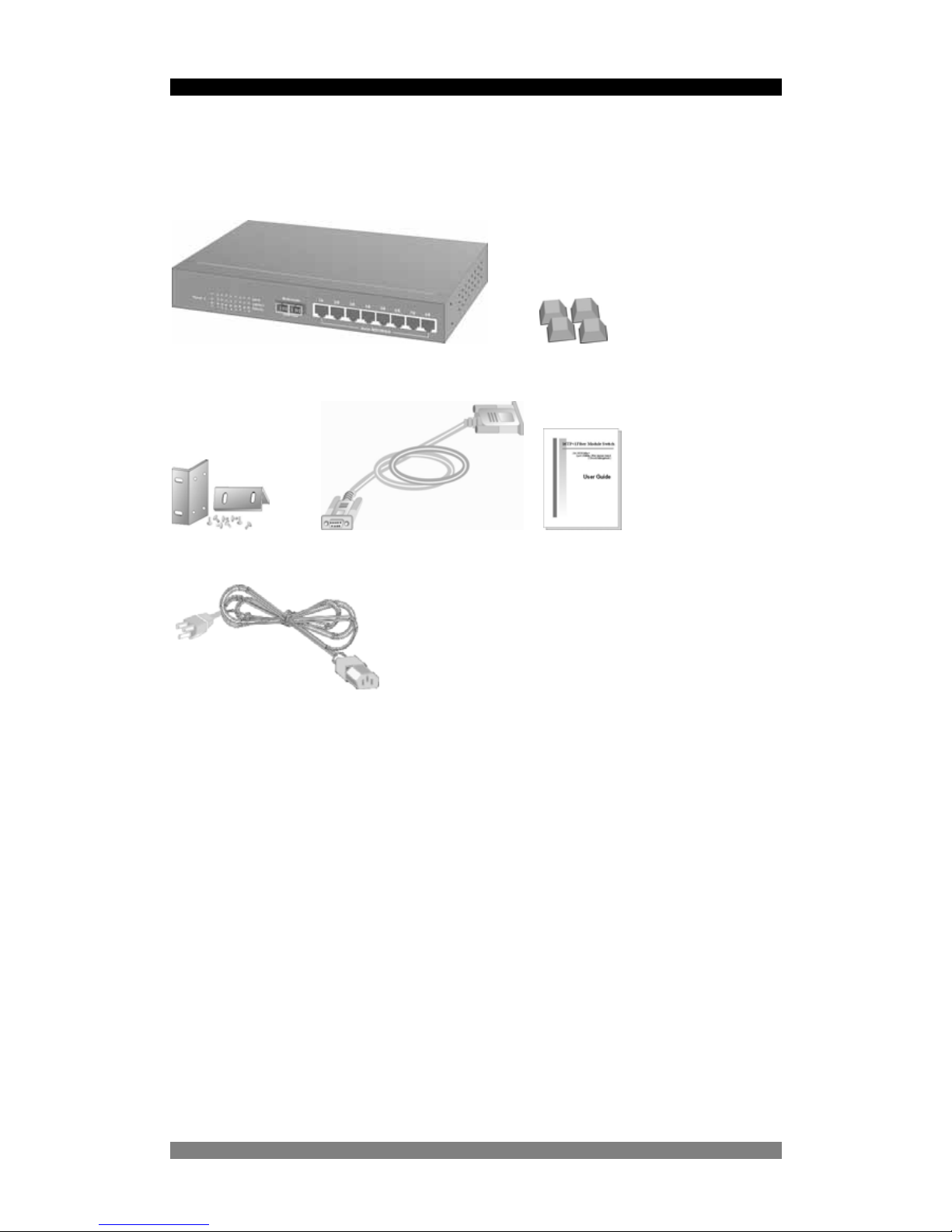
Package Contents
Unpack the contents of the carton and verify them ag ainst the checklist below.
8 Port SNMP Managed Switch Rubber Feet
Rack-mounted Kit RS-232 cable User Guide
Power Cord
Figure 1. Package Contents
Compare the contents of your 8 Port SNMP Managed Switch package with the standard
checklist above. If any item is missing or damaged, please contact your local dealer for service.
Product Number 0-15910xx-x © T y co Electronics 2004 PL0357 Issue A
Page 4

8 Port SNMP Managed Switch – User Manual Page 4
Product Number 0-15910xx-x © T y co Electronics 2004 PL0357 Issue A
Management Methods
The 8 Port SNMP Managed Switch supports following mana gement methods:
• Console and Telnet Management
• Web-based Management
• SNMP Network Management
Console and Telnet Management
Console Management is done through the RS-232 Console Port. Managing the 24 Port SNMP
Managed Switch in this method requires a direct connection between PC and the 8 Port SNMP
Managed Switch. While Telnet management is done over the network. Once the 8 Port SNMP
Managed Switch is on the network, you can use Telnet to log in and change the configuration.
The automatic log-out times is currently set at less than 1 minute, however this duration will be
extended in the next software release.
Web Based Management
The switch can be managed using a standard web browser that supports Java applets. This
interface has the same functionality as the console/Telnet interfaces but is more user-friendly.
See page 38 for details.
SNMP Network Management
SNMP (Simple Network Management Protocol) provides a means to monitor and control a
network device, and to manage configurations, statistic collection, performance and security.
Data is passed from SNMP agents, which are hard ware & software proce sses reporting activity
in each network device to the workstation console used to oversee the network. The agent
returns information contained in a MIB (Management Information Base), which is a data
structure that defines what is obtainable from the device and what can be controlled.
Page 5
8 Port SNMP Managed Switch – User Manual Page 5
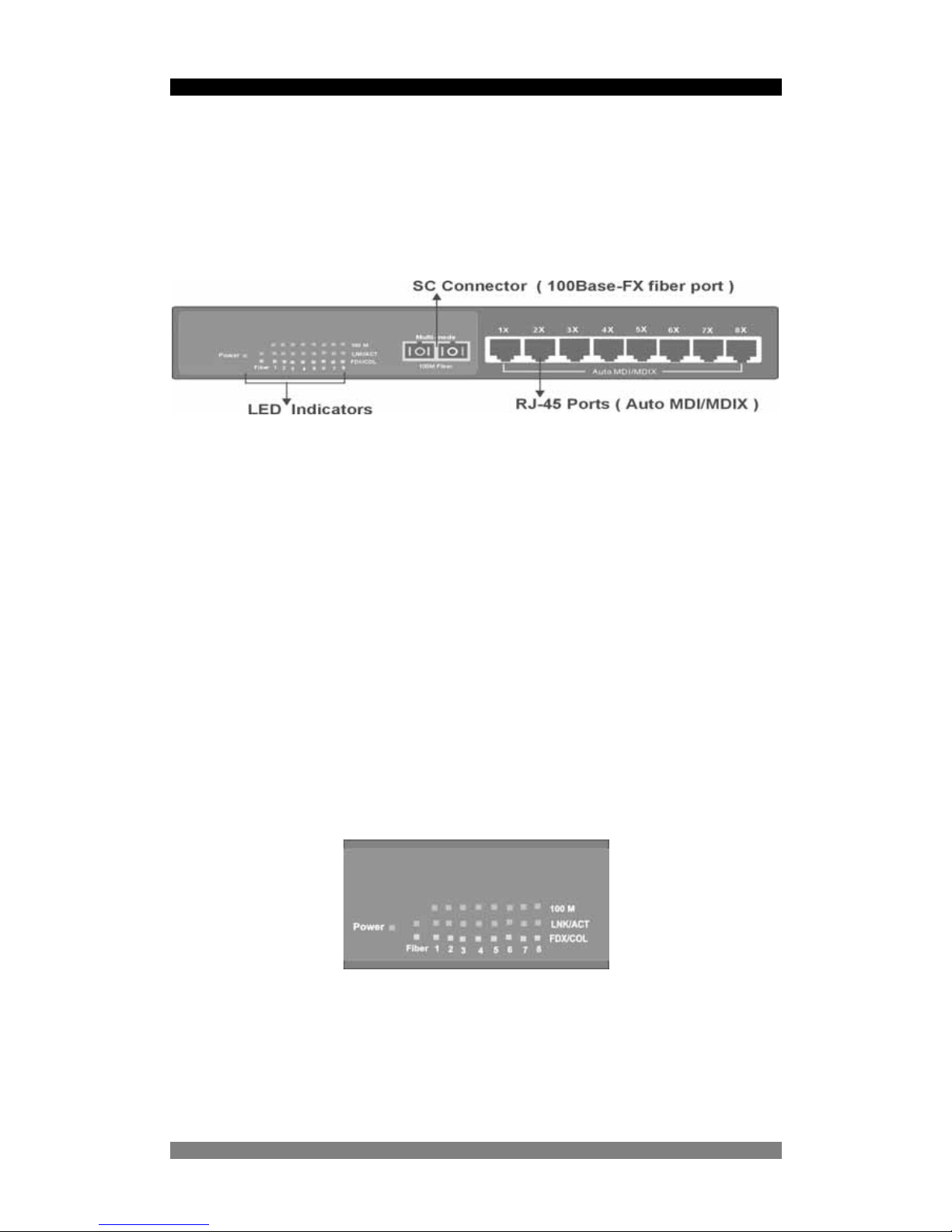
Hardware Description
The 8 Port SNMP Managed Switch has 8-port auto-sensing Ethernet RJ-45 connectors and
one fibre uplink connector . The LED Indicato rs are also located on the fro nt panel of the Switch.
Product Number 0-15910xx-x © T y co Electronics 2004 PL0357 Issue A
Figure 2. The Front Panel of 8 Port SNMP Managed Switch
Expansion Slots for Option Modules
10/100Base-TX Auto MDI/MDIX RJ-45 Ports
The 10/100Mbps auto-sensing ports auto-negotiate speed and duplex mode for 10Base-T or
100Base-TX device connection. The auto-MDI/MDIX function enables the direct connection
another switch or workstation without needing to select either a straight or cross-over cable.
100Base-FX Fibre Port
The switch has a dedicated fibre uplink port that operates at 100Mbit/s. This port can also be
configured to half or full duplex operation.
LED Indicators
Figure 3. The LED Indicators
Page 6
8 Port SNMP Managed Switch – User Manual Page 6
All LED indicators are located on the front panel of the 8 Port SNMP Managed Switch and
provide a real-time indication of switch and operational status. The following table details the
LED states:-
LED Status Description
Green Power On
PWR
Off Power is Off.
Green The port is operating at the speed of 100Mbps.
10/100
Off No device is attached or in 10Mbps mode
Green The port is connected to an Ethernet device.
Blinks The port is receiving or transmitting data
LK/ACT
Off No device is attached
Orange The port is operating in Full-duplex mode
Blinks Collision of packets is occurring on the port
FD/COL
Off No device is attached or the port is in half-duplex mode
Figure 4. Descriptions of LED Indicators
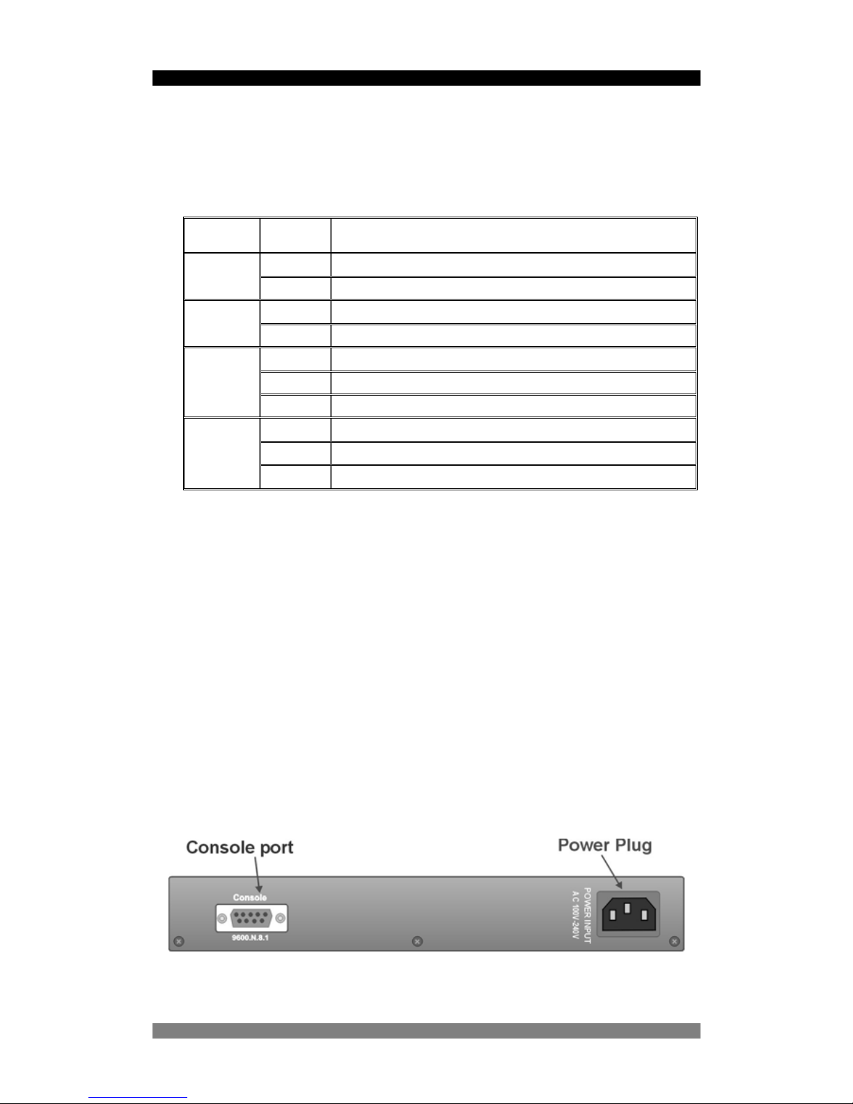
Rear Panel
The 3-pronged power socket and the On/Off switch are located at the rear panel of the switch.
The switch operates over the range 100-240V AC, 50-60Hz without adjustment.
Console Port
The switch can be fully managed using the consol e port p roviding a direct conn ection bet we en
the switch and an end station such as a PC via the supplied RS-232 cable. See page 12 for
details.
Figure 5. The Rear Panel of the 8 Port SNMP Managed Switch
Product Number 0-15910xx-x © T y co Electronics 2004 PL0357 Issue A
Page 7

8 Port SNMP Managed Switch – User Manual Page 7
Product Number 0-15910xx-x © T y co Electronics 2004 PL0357 Issue A
Diagnostic Test
After the installation is completed and AC power is applied to the Switch, the system will
automatically perform a diagnostic test. If a console session is active at this time then it is
possible to see each stage of this start-up and test p ro cedure as it is carried out.
This procedure will take up to 3 minutes to complete; please be patient!!
Upon completion the switch will start in a default condition and begin to pass traffic.
Page 8

8 Port SNMP Managed Switch – User Manual Page 8
Product Number 0-15910xx-x © T y co Electronics 2004 PL0357 Issue A
Installation
Pre-Installation Requirements
Before you start hardware installation, make sure your installation environment has below
items:
PC with 10/100Mbps Ethernet NICs / 100Mbps Fiber NICs:
Y our PC must have a standard Ethernet RJ-4 5 interface to connect to the Switches copper port.
UTP cable with RJ45 connectors: Ensure that you use a tested cable.
AC Power: 100 to 240V A C at 50/60 Hz: Make sur e that the power is accessible and the AC
power cable can be and disconnected and connected easily.
Dedicated power supply: Use dedicated AC or power conditioners to supply reliable
electrical power to the network devices.
A dry cool place: Keep the Switch away from moisture. A void direct sunlight, sources of heat,
and a high amount of electromagnetic interference.
Mounting tools: If you intend to mount the Switch in a rack, make sure you have all the tools,
mounting brackets, screws etc.
Caution:
Cabling must be away from sources of electrical noise such as radio, computers, transmitters,
broadband amplifiers, power lines etc.
Airflow around the Switch and through its vents on the rear must not be re stricted.
Mounting the Switch
The 8 Port SNMP Managed Switch is suitable for use in an office environment where it can be
rack-mounted in standard EIA 19-inch racks or standal one. Ensure that you order the mounting
brackets if you intend to rackmount the switch.
Desktop Mounting
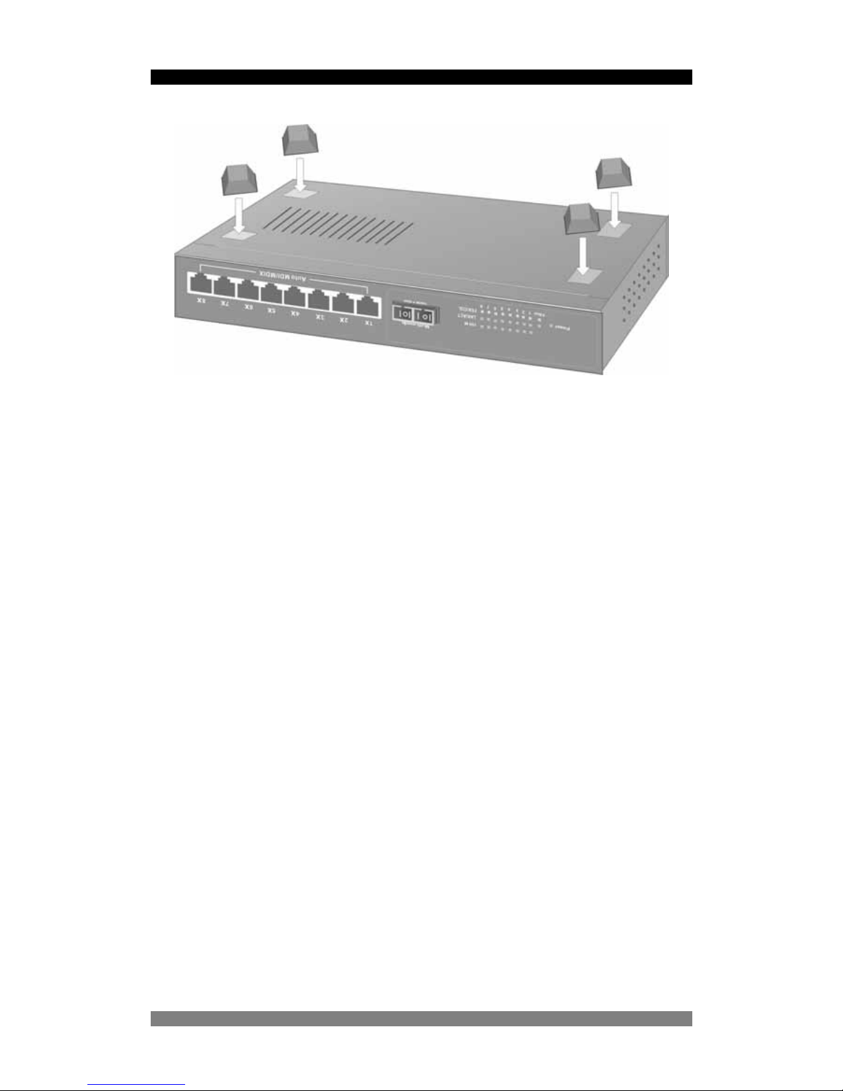
Set the Switch on a sufficiently large flat space with a power o utlet nea rby, and n ear the cente r
of all networked devices.
Make sure mounting surface on the bottom of the Switch is grease dust free.
Remove adhesive backing from the supplied rubber feet.
Page 9
8 Port SNMP Managed Switch – User Manual Page 9
Figure 3-1. Attaching Rubber Feet to each corner on the bottom of the
Switch
Apply the Rubber Feet to each corner on the bottom of the Switch. These footpads can prevent
the Switch from shock/vibrations.
Caution: Do not place objects on top of the Switch.
Product Number 0-15910xx-x © T y co Electronics 2004 PL0357 Issue A
Page 10
8 Port SNMP Managed Switch – User Manual Page 10
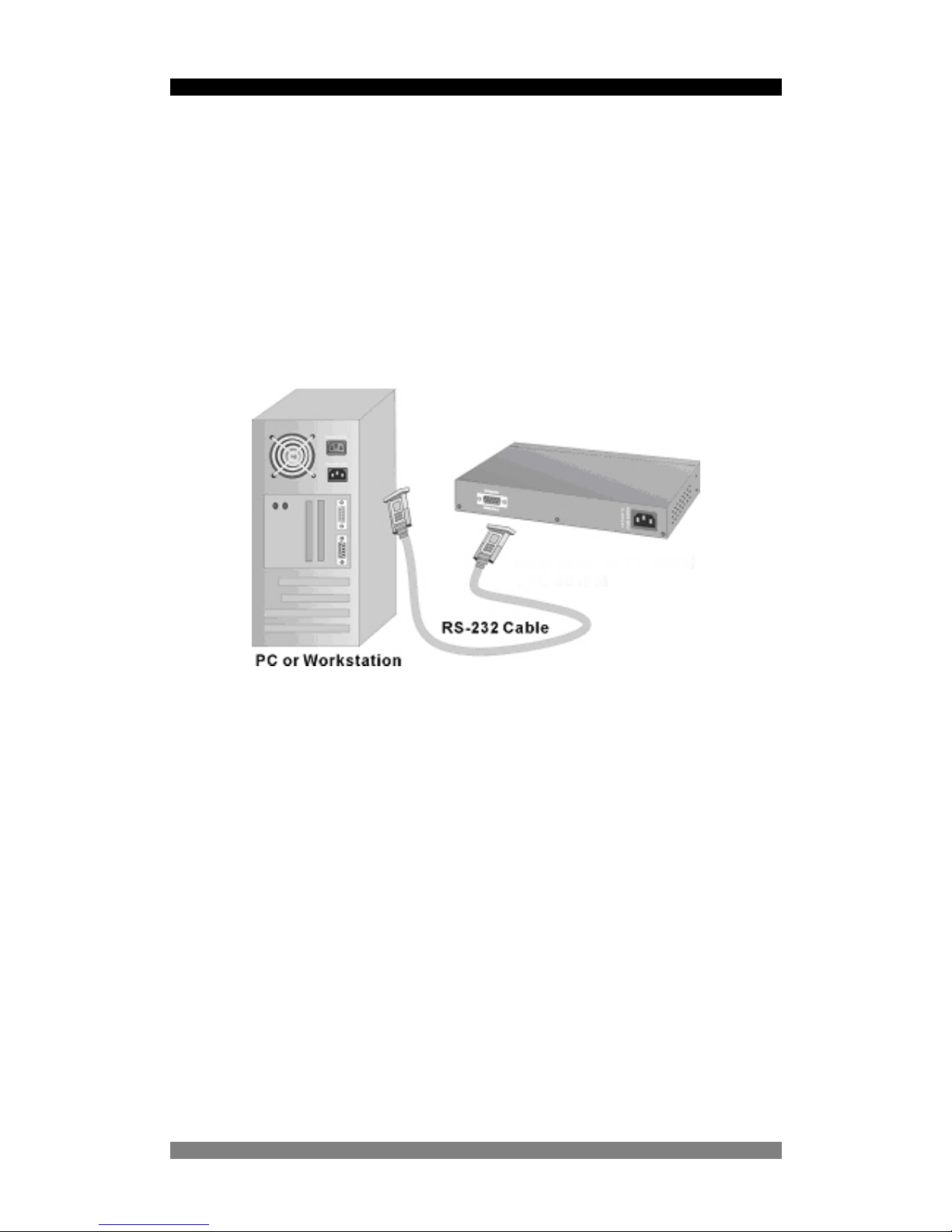
Connecting to the Switch
The Console port is a male DB-9 connector located on the front pane l of the switch that enables
a connection to a PC or terminal for monitoring and configuration. Use the supplied RS-232
cable with a female DB-9 connector to connect a terminal or PC to the Console port.
The Console configuration allows you to program the Switch to enable a user at a remote
location to communicate with the unit as if the console terminal were directly connected.
Figure 3-4. Connecting the 8Port SNMP Managed Switch to a terminal via
RS-232 cable
Product Number 0-15910xx-x © T y co Electronics 2004 PL0357 Issue A
Page 11

8 Port SNMP Managed Switch – User Manual Page 11
Product Number 0-15910xx-x © T y co Electronics 2004 PL0357 Issue A
Quick Start Guide
If you do not need to apply VLANs, Quality of Service, adjust any settings or manage the switch
via the network, then the switch can be used “straight-from-the-box” to carry network traffic. In
that case, no further action is needed. If you want to use the management settings or controls,
then a little work is needed to configure the switch.
1. After the installation is completed and AC power is applied to the switch, the unit will
automatically perform a diagnostic test. The switch loads its operating code from memory
and performs a full power-on self test. The screen will display the self-test progress, but do
not press any keys at this stage. This power-up sequence takes approx. 90 seconds to
complete. The web interface will take a further 30 seconds to become operational.
2. Configure you PC terminal emulation program such as HyperTerminal to allow it to
communicate with the switch via the supplied serial cable connected to the front panel
Console port. Set the emulation program for 9600, 8, No Parity , No Flow Control. See page
12 for details
3. When the password and user name prompt is displayed, use the default userna me of root
in lower case letters. Use the password root. The main menu screen will be displayed. Use
either cursor keys or the tab key to navigate up and down the menu. Select the item using
the <CR> key. The <ESC> key will return you to the previous menu level.
4. If the switch is to be managed over the LAN using the Telnet, SNMP or the web browser
functions, then an IP address is to be assigned to the switch. See page 20 for details. If the
switch is not being managed over the LAN, then go to page 12 below.
5. Once an IP address has been assigned to the switch, it should be possible to PING the
switch over the network. This will prove that the switch is present and responding correctly
to network requests.
6. Now that the switch can be accessed over the network, use a browser application to open
up the configuration screens. Enter the switch IP addre ss into the browser Ad dress window
and use the same user name and password set as in 3 above.
7. Using the preferred method (console, Telnet or web brow ser), configure the swi tch to meet
your network requirements. Always save the configuration at the end of each action.
8. If you need to revert the switch back to the factory default configuration, then see p ag e 37.
Page 12
8 Port SNMP Managed Switch – User Manual Page 12
Management Using The Console
Configuring the Console Interface
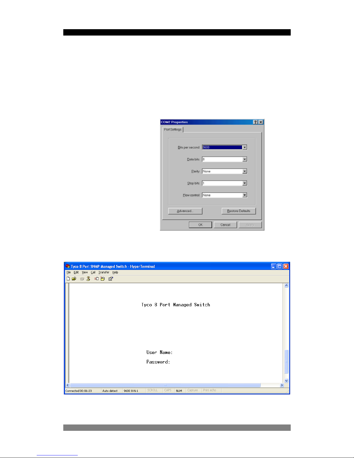
When the connection between Switch and PC is complete, turn on the PC and run a terminal
emulation program such as Hyper Terminal and configure its communication p arameters to
match the following default characteristics of the console port:
Baud Rate: 9600 bps
Data Bits: 8
Parity: none
Stop Bit: 1
Control flow: None
Figure 6. Serial communication settings
Figure 7. Initial Start-Up Screen
Product Number 0-15910xx-x © T y co Electronics 2004 PL0357 Issue A
Page 13

8 Port SNMP Managed Switch – User Manual Page 13
Product Number 0-15910xx-x © T y co Electronics 2004 PL0357 Issue A
After you have finished parameter settings, click “OK“ on the configuration screen (Figure 6).
Press the <CR> return key a couple of times and the start screen (Figure 7) is displayed. Enter
the default value user name root in lower case letters, enter the<CR> key and then enter the
default password of root. The Main Menu of the console management appears (Figure 8). Note
that these username and password values can be changed as detailed on page 21.
Page 14

8 Port SNMP Managed Switch – User Manual Page 14
Menu Navigation
To navigate all these menus, use the following keys:-
• Tab: Move the cursor to next item.
• Backspace: Move the cursor to previous item.
• Enter: Select the item.
• Space: Toggle selected item to next value in sequence
• Esc: Go back to the action list or the previous menu
Do not use the cursor up/down or side keys on the numeric pad, as on this version of software,
the results are un-predictable. This issue will be corrected on future software versions.
Note that some menus have an action line at the bottom of the screen. This provides basic
context instructions such as Edit, Save and Quit
Main Menu S c reen
After login you will see the Main Menu screen below. Use the <tab> or cursor keys to step
through the sub-menus. Select the required sub-menu using the <CR> or enter key.
Figure 8. Main Menu Screen
The sub-menus are:-
• Status and Counters: Displays Port Status, Port Counters and System Information
• Switch Static Configuration : This large menu enables the configuration of key
values such as IP address, Ports, Trunking, Mirroring, VLANs, QoS, Security,
Broadcast filtering etc.
• Protocol Related Configuration: Enables the configuration of Spanning Tree, SNMP,
GVRP and LACP trunking.
• Reboot Switch/System Reset Configuration: Restores factory default values or
restarts the switch.
Product Number 0-15910xx-x © T y co Electronics 2004 PL0357 Issue A
Page 15

8 Port SNMP Managed Switch – User Manual Page 15
Port Status And Counters
This menu provides a method of viewing the current port status and counter statistics in
near-real-time. The first option in the sub-menu is Port Status:-
Figure 9. Port Status Screen
This read-only screen lists the status of every port on the switch To change values you need to
use the Port Configuration Screen. The key values are:-
• Type: Display the port type.
• Enabled: Displays the port enabled or disable state depended on the user setting.
Enabled will be display “Yes”, disabled will be display “No”.
• St atus: Displays the port link or no link status, “Down” is no link, and “Up” is link valid.
• Mode: Displays the port speed and duplex.
• FlowCtrl: Display the flow control status (enabled or disabled).
Product Number 0-15910xx-x © T y co Electronics 2004 PL0357 Issue A
Page 16

8 Port SNMP Managed Switch – User Manual Page 16
Port Counters
This sub-menu lists the real-time values from each port on the switch. This information is
especially useful for fault-finding purposes.
Figure 10. Port Counters Screen
These counters display both transmitted and received packet counts together with the number
of good and bad packets including the numbe r of collisions (half-duplex mode only).
• <Quit>: Exit the page of port status, and return to previous menu.
• <Reset All>: Set all counters to 0.
Product Number 0-15910xx-x © T y co Electronics 2004 PL0357 Issue A
Page 17

8 Port SNMP Managed Switch – User Manual Page 17
System Information
The sub-menu screen displays information such as unit description, switch hardware, software
versions and the MAC address. Note that this is a read-only menu.
Figure 11. System Information Screen
Product Number 0-15910xx-x © T y co Electronics 2004 PL0357 Issue A
Page 18

8 Port SNMP Managed Switch – User Manual Page 18
Switch Static Configuration
This menu provides the primary method of configuring the switch and its associated values.
Figure 12. Switch Static Configuration Screen
The Switch Static Configuration Screen has the following sub-menus:-
• Administration Configuration:- Provides device description information, IP address
configuration, User Name and Password configuration.
• Port/Trunk Configuration:- Enables the switch ports to be configured and also port
trunk groups to be established.
• Port Mirroring:- Selects either enabling or disabling of the Port Mirror function.
• VLAN Configuration:- Enables VLANs, select the type of VLAN required and add/edit
VLANs
• Priority Configuration:- Places traffic flowing through ports into either the High or Low
priority queues.
• MAC Address Configuration:- Sets up the MAC address security and filtering
attributes.
• Misc Configuration:- Enables MAC Address Security, Switch Ageing T im e, Broadcast
Storm filtering and Bridge Transmit Delay Bound.
Product Number 0-15910xx-x © T y co Electronics 2004 PL0357 Issue A
Page 19

8 Port SNMP Managed Switch – User Manual Page 19
Administration Configuration Screen
This is one of the sub-menus leading to the IP Configuration Screen.
Figure 13. The Administration Configuration Menu
Device Information
Use this sub-menu to change the device name, location and descriptions etc. Select the Edit
field using the Tab key and then Return key to move the edit fields alongside each variable.
When a line has been edited, use the Tab key to move to the next field or the Esc key to move
back to the Action line.
Figure 14. The Device Information Menu
Product Number 0-15910xx-x © T y co Electronics 2004 PL0357 Issue A
Page 20

8 Port SNMP Managed Switch – User Manual Page 20
IP Configuration
This screen is used to set the IP address, Sub-Net Mask and Default Gateway for the switch.
These settings are only required if the switch is to be managed over the network using Telnet,
the web browser or SNMP management.
Figure 15. The Network Configuration Menu
This menu displays the switch MAC address and enables the IP address of the switch to be
configured to the network. To change the IP switch setting: -
1. Use the <TAB> to select the Edit field
2. Enter <Return> and the cursor will highlight the IP Address field.
3. Enter the new IP Address as required.
4. Use <TAB> key to highlight the Subnet Mask field.
5. Enter the Subnet mask address as required.
6. Use <TAB> keys to highlight the default gateway field.
7. Enter the IP address of the default gateway as required.
8. Use the <Esc> key to jump to the Action line and then tab to the Save field and then
select the Save using the <CR or Return> key to save the IP address changes.
9. The Action line will display a prompt stating that the switch must be restarted before the
settings can take place. This step is essential as the new IP values will only be applie d
when the switch is rebooted.
Product Number 0-15910xx-x © T y co Electronics 2004 PL0357 Issue A
Page 21

8 Port SNMP Managed Switch – User Manual Page 21
10. Navigate up to the Main Menu using the Esc key and then select the System Reset
Configuration option and then select the System Reboot option. This will cause the
switch to be restarted. Note:- After the reboot has commenced, do not press any
keys and just let the switch work through the self-test and start-up processes.
This can take about 1-2 minutes.
11. After restarting the switch it is advisable to check that IP changes have been made
current by checking the Administration Configuration>IP Configuration menu again.
The following menu options enable detailed changes to the serial port and SNM P configuration.
These menus are not used in most instances.
Change User Name and Password
The Administration Configuration screen has separate options for changing the User Name and
the Password for the switch. The default values are:-
• User Name = root
• Password = root
Note that these values are case-sensitive. To change either value, select the required option in
the Administration Configuration screen and the select the Edit mode from the action line.
Follow the instruction to make the change and then quit from the edit mode using the <CR> key
or the Esc key, depending on the mode. Ensure that the new User Name is saved by selecting
the Save option in the action line. The new password is saved automatically.
Figure 16. Changing the password
Product Number 0-15910xx-x © T y co Electronics 2004 PL0357 Issue A
Ensure that you make a note of the changed user name and password values and save
this information in a secure location. For security reasons, we cannot assist in the
recovery of changed password and user name values. This is the responsibility of the
system administrator.
Page 22

8 Port SNMP Managed Switch – User Manual Page 22
Port/Trunk Configuration
This menu section controls the detailed per-port configuratio n of the switch and is selected from
the Switch Configuration menu screen. The following port controls can be configured from this
menu:-
• Port Enable
• Auto-Negotiation Mode
• Port Speed and Duplex Mode
• Port Flow Control
• Trunk Group Membership
Figure 17 Port/Trunk Configuration Menu
Selecting the required Port Mode
To edit the mode of a selected port, use the <Tab> key to move the cursor in the action line to
the <Edit> mode. Then press the <CR> return key and the cursor will highlight the Enable
status of Port 1. Use the <Tab> key to navigate to the required port mode and then use the
<Space> key to toggle the values of that control. Use the <Backspace> key to move to the
previous port modes.
Product Number 0-15910xx-x © T y co Electronics 2004 PL0357 Issue A
Page 23

8 Port SNMP Managed Switch – User Manual Page 23
Product Number 0-15910xx-x © T y co Electronics 2004 PL0357 Issue A
Port Enable
This allows the copper RJ-45 or fibre uplink port to be set to accept and process traffic. The
default setting is Enabled.
Port Auto-Negotiation
This allows the copper RJ-45 port to be set to negotiate the optimum mode with the co nnecte d
equipment. The default setting is Enabled.
Port Speed/Duplex
This allows the copper RJ-45 or fibre uplink port to be set to negotiate the optimum mode with
the connected equipment. Note that this setting is superceded by the Port Auto-negotiation
mode. For example, if the port is set to Auto-Negotiate, then the Port Speed/Duplex mode is
ignored. The default setting is 100Mbit/s and Full Duplex.
Port Flow Control
This allows the copper RJ-45 or fibre uplink port to negotiate with connected equipment to
implement a flow control process using embedded Pause frames. The default setting is On.
Port Group
This allows the copper RJ-45 port to be a member of any 1 of 4 separate trunk groups. Select
the option and use the <Sp ace> key to toggle bet ween the available trunk grou p s (1-4). In this
trunk mode, the selected ports are made members of the same trunk group to create an
aggregated higher speed link. The default setting is None.
Notes:-
1. The fibre uplink port cannot be a member of a trunk group.
2. The members of the trunk group must all operate at the same speed.
Page 24

8 Port SNMP Managed Switch – User Manual Page 24
Port Mirroring
This menu section controls the port mirroring configuration of the switch and is selected from
the Switch Configuration menu screen. This menu section controls the routing of packets from a
selected port to a target port for test purposes such as the connection of a Sniffer device to
observe traffic on selected port(s). This function is selected from the Switch Conf iguration menu
screen.
Figure 18. Port Mirroring Screen
The default mode is disabled and to activate port mirroring, select the menu and then use the
<Edit> key to move to the Port Mirroring St ate field. Use the <Space> key to toggle the state to
Enabled. A new menu area is displayed with the following key fields:-
• Analysis Port is the port that is connected to the Snif fer device. Traff ic from the ports to
be monitored are output on this port.
• Mirrored Ports are the ports that are to be have their traf fic routed t o the Analysis port.
Note that you can select to have just the TX or just the RX or both direction of traf f ic on
the Mirrored port sent to the Analysis port. Note that due considerat ion of the available
bandwidth transmitted ob the Analysis port needs to be taken as packet loss will occur
if too much mirrored traffic is routed to the Analysis port.
Product Number 0-15910xx-x © T y co Electronics 2004 PL0357 Issue A
Page 25

8 Port SNMP Managed Switch – User Manual Page 25
Port VLAN Configuration
This menu section controls the VLAN configuration of the switch and is selected from the Switch
Configuration menu screen. The switch supports the following VLAN modes:-
• Port based,
• IEEE802.1Q
• IEEE802.1Q with GVRP
The default configuration is Disabled.
Note that VLANs have to be enabled from the Console or Telnet sessions, as they
cannot be directly activated from the web browser in this version of software. This
limitation is being corrected in future versions of the software. Once the VLANs have
been enabled in via the console/Telnet session, the VLANs can be configured and
controlled via the web browser.
The first menu displayed is the overall VLAN control menu:-
Figure 19. VLAN Configuration menu
This menu allows basic control of the VLAN and its membership. Select the Configure VLAN
Type menu option and a new screen is displayed. If the switch is in the default setting of
Disabled, then this will need to be changed to the required VLAN type listed above. Use the
<Edit> key in the action bar to move into the options area of the screen. Then use the <Space>
key to toggle through the VLAN options. In each case, a new screen is displayed with the
settings appropriate to the selected VLAN type.
Product Number 0-15910xx-x © T y co Electronics 2004 PL0357 Issue A
Page 26

8 Port SNMP Managed Switch – User Manual Page 26
Product Number 0-15910xx-x © T y co Electronics 2004 PL0357 Issue A
Port Based VLANs
After the Port Based VLAN option has been selected and saved, a new screen is displayed
which allows VLAN Group Membership to be created with the following values:-
• VLAN Name
• VLAN Group ID
• VLAN Port Membership
VLAN Name
This is a local value intended to provide a simple description of the VLAN, such as Sales,
Accounts etc.
VLAN Group ID
This is the VLAN ID that is used to provide a number for the specific VLAN. The legal range is 1
to 4094, with 1 being the default value. It is recommended that a VLAN ID number other than 1
be applied to new port based VLAN configurations. The VLAN Group ID must be a unique
number.
VLAN Port Membership
Ports that are to be members of this VLAN are specified in the table by using <Tab> key to
move to the Port area and then the <Space> key to toggle the membership status between
None and Member. Select the req uired p ort s to be members of this VLAN and th en use <Esc>
to move to the action line and then Save the settings. This port membership can also be created
using the Create VLAN Group menu option.
Repeat the above for each port based VLAN.
Page 27

8 Port SNMP Managed Switch – User Manual Page 27
Product Number 0-15910xx-x © T y co Electronics 2004 PL0357 Issue A
IEEE802.1Q VLANs
This is a more complex form of VLAN that reacts to the tagging field in the Ethernet packets.
This enables the switch to be used in larger networks where the VLAN modes are configured
directly on the switch. In large scale networks, the VLANs are sometimes centrally registered
and administered using GVRP (Generic VLAN Registration Protocol). In this case, use the
VLAN option IEEE802.1Q With GVRP, not this IEEE802.1Q option.
1. Select the Configure VLAN Type option and then use the <Tab> key to select the
<Edit> option and then enter <CR> to select the mode. The cursor will now be on the
VLAN Mode field. Use the <Space> key to toggle through the options to locate
IEEE802.1Q. A new menu is displayed.
2. Use the <Tab> key to move into the port field of the menu. Enter the number of the
tagged VLAN ID directly into the VLAN ID field. If the device connected to this port does
not support tagged VLANs, the ingress traffic will have the specified default tag number
added to each packet. This allows legacy devices that do not support tagging to
interoperate with tagged VLAN systems.
3. Use the <Tab> key to move into the Ingress Filter field of the menu. Use the <Space>
key to toggle between Disable and Enable. In the default state, all traffic is forwarded
irrespective of the VLAN tag value. When this filter is Enabled, then only packets with
the correct VLAN tag will be forwarded, depending on the value of the Acceptable
Frame Type Filter.
4. Use the <Tab> key to move into the Acceptable Frame Type field of the menu. Use
the <Space> key to toggle between All and Tag Only. This is used in conjunction with
the Ingress Filter above to filter out non-tagged traffic.
Page 28

8 Port SNMP Managed Switch – User Manual Page 28
Product Number 0-15910xx-x © T y co Electronics 2004 PL0357 Issue A
Create VLAN Group
This menu section controls the VLAN Group Membership of the switch and is selected from the
Switch Configuration menu screen. This allows specified port s to be made memb ers of specific
VLAN groups.
VLAN Name
This is a local value intended to provide a simple description of the VLAN, such as Sales,
Accounts etc.
VLAN Group ID
This is the VLAN ID that is used to provide a number for the specific VLAN. The legal range is 1
to 4094, with 1 being the default value. It is recommended that a VLAN ID number other than 1
be applied to new port based VLAN configurations. The VLAN Group ID must be a unique
number.
VLAN Port Membership
Ports that are to be members of this VLAN are specified in the table by using <Tab> key to
move to the Port area and then the <Space> key to toggle the membership status between
None and Member. Select the req uired p ort s to be members of this VLAN and th en use <Esc>
to move to the action line and then Save the settings.
Edit/Delete VLAN Group
This menu section is selected from the Switch Configuration menu screen and allows an
existing VLAN group to be edited or even deleted. When this option is selected, all existing
VLAN groups on the switch are displayed. Use the <Tab> key to navigate to the <Edit> field or
<Delete> field on the Action line and then use the <CR> key to select the edit option.
If <Edit> was selected, the cursor now moves to the VLAN group area and use the <Tab> key
to select the required group and apply the required changes. Use the <Esc> key to return to the
action line and then <Save> the changes.
If <Delete> was selected, the cursor now moves to the VLAN group area and use the <Tab>
key to select the required group and then <CR> to delete the VLAN group. Use the <Esc> key
to return to the action line and then <Save> the changes. Note that a deleted VLAN group
cannot be recovered after the process has been <Saved>
Page 29

8 Port SNMP Managed Switch – User Manual Page 29
Product Number 0-15910xx-x © T y co Electronics 2004 PL0357 Issue A
QoS Priority Configuration
The switch supports basic QoS operation with the ability to map the 0-7 priority levels in
IEEE802.1p to either the low or high priority egress queue buffers. In addition the relative
weighting of high to low packets egressing from the switch can also b e programmed. This menu
section is selected from the Switch Configuration menu screen.
Modify the Egress Mapping
After the Priority Configuration menu has been selected, the priority screen is disp layed and this
enables the control of the QoS egress mapping. To adjust the mapping, select <Edit> from the
action line and the cursor moves to the first map level. Use the <Space> key to toggle between
<Low> and <High> settings. The default mapping is Levels 0-3 are Low priority and Levels 4-7
are High priority .
Modify the Egress Weighting
The switch can be programmed to control the relative flow of high and low priority packet s from
the egress port. Note that this weighting algorithm is applied to the whol e switch and not specific
ports. To adjust the weighting algorithm, select <Edit> from the action line and the cursor
moves to the first map level. Use the <Tab> key to move through the mapping options to the
High/Low Queue Service Ratio field. Then select the required algorithm using the <Sp ace>
key . The weighting options are:-
Weighting Action
H->L All high priority packets are sent before any low priority packets (default)
FIFO The first packet to arrive is sent out first (no actual priority is applied)
1:1 One high priority packet is sent followed by a low priority packet (if available)
2:1 Two high priority packets are sent followed by one low priority packet (if available)
3:1 Three high priority packets are sent followed by one low priority packet (if available)
4:1 Four high priority packets are sent followed by one low priority packet (if available)
5:1 Five high priority packets are sent followed by one low priority packet (if available)
6:1 Six high priority packets are sent followed by one low priority packet (if available)
7:1 Seven high priority packets are sent followed by one low priority packet (if available)
Use the <Esc> key to return to the action line and ensure that the settings are saved by
selecting the <Save> field.
Page 30

8 Port SNMP Managed Switch – User Manual Page 30
Product Number 0-15910xx-x © T y co Electronics 2004 PL0357 Issue A
MAC Address Configuration
This menu section is selected from the Switch Configuration menu screen and enables
configuration of the static or filtered MAC addresses. These setting s are only needed for certain
security operations and are not generally used.
In some instances, it is necessary to manually apply a fixed or static address into the tables of
the switch. When you add a static MAC address, it remains in the switch's address table,
regardless of whether the device is physically connected to the switch. This saves the switch
from having to re-learn a device's MAC address when the disconnected or powered-off device
is active on the network again.
Add A Static MAC Address
From the MAC Address Configuration menu select the option S tatic MAC Address. A new menu
is displayed of the existing static MAC addresses and then select <Add> from the action line. A
new menu is displayed that requests the MAC address value and the physical port that is
associated with the static address value. Ensure that a legal MAC addre ss is entered here a s a
warning message is displayed on detection of an illegal address. When these values have bee n
entered, use the <Esc> key to return to the action line and then select the <Save> option to
ensure that the MAC values are stored. The menu will display each static MAC addres s and the
associated port in the switch.
Page 31

8 Port SNMP Managed Switch – User Manual Page 31
Misc Configuration
This menu section is selected from the Switch Configuration menu screen and enables
configuration of the remaining switch-specific variables such as Port Security, Ageing Table
Interval, Broadcast Storm etc.
Figure 20. Misc Configuration Menu
Port Security
This mode is used to prevent a specified port from learning new MAC addresses. This is used to
ensure that un-authorised devices cannot be connected and gain LAN access from the physical
port. Only ingress packets with the MAC address matching an associated Static MAC address
will be forwarded. Packets not matching this profile will be rejected.
To activate this port security mode, select the Port Security option and then use the <Tab> key
to select <Edit> in the action line. Enter <CR> and the cursor will highlight the security field of
Port 1. Use the <Space> key to toggle the value from <Disabled> to <Enabled>. When the port
value is <Enabled> the port will not learn new MAC addresses and only packets that match the
Static MAC address will be forwarded. Use the <Esc> key to return to the action line and then
select <Save> to ensure that the security settings are saved.
There is a minor bug in this software that fails to highlight the <Save> option in the action line.
This will be corrected in future versions. Check that the values have been saved correctly by
going to the upper level menu and then re-selecting Port Security.
Product Number 0-15910xx-x © T y co Electronics 2004 PL0357 Issue A
Page 32

8 Port SNMP Managed Switch – User Manual Page 32
Product Number 0-15910xx-x © T y co Electronics 2004 PL0357 Issue A
MAC Aging Time Setting
This setting specifies the time that a dynamic MAC address can remain in the switch tables
before the value is “aged out”. The valid range is 300 to 765 second s. The def ault value is 300
seconds, which is the industry standard duration. This value rarely needs to be modified.
Broadcast Storm Filtering
This is used to limit the number of packets flowing through the switch that do not have
associated entries in the switch tables (Destination Look-Up Failures) or excessive boardcast
transmissions. In some instances, this high level of DLF/broadcast traffic can degrade network
performance. To minimize this problem, the switch can be programmed to limit the amount of
broadcast traffic that can flow through the switch. In normal networks, only a few percent of
traffic would normally be broadcast s.
This mode is accessed from the Misc. Configuration screen and is changed by selecting <Edit>
from the action line and the cursor then moves to move to the Broadcast Storm field. Use the
<Space> key to step through the available values:-
• No
• 5%
• 10%
• 15%
• 20%
• 25%
The default value is No but for normal networks, a selected value of 5% would serve to limit the
number of excessive broadcasts and yet allow normal levels of broadcasts to flow. After the
required limit value has been selected, use the <Esc> key to move to the action line and then
select <Save> to store the value.
Page 33

8 Port SNMP Managed Switch – User Manual Page 33
Product Number 0-15910xx-x © T y co Electronics 2004 PL0357 Issue A
Max Bridge Transmit Delay Bound
This control is used in association with QoS Configuration to control the time that packets may
be queued in the switch. If the packet is stored in the switch for a time exceeding the specified
amount, then it is dropped. These settings do not need to be changed except for networks
where time-sensitive prioritized traffic is used.
Max Bridge T ransmit Delay Bound
If time bounded prioritisation is used then select this control and set it to a non-zero value i.e:-
• 1 Sec
• 2 Sec
• 4 Sec
Packets exceeding the specified time in the switch will be dropped. The default value is 0. Save
the settings.
Enable Delay Bound
This control works in a different manner in that it measures the time that a low priority packet
has been stored in the switch. If the stored time exceeds the value specified in the Max Delay
Time control, then the packet is sent. Ensure that the Max Bridge Transmit Delay Bound
control contains a non-zero value. Save the settings.
Max Delay Time
This control specifies the duration in milli-seconds that a low priority packet can be stored in the
switch before it is automatically sent. The available range is 1ms to 255ms. This control works
in conjunction with the Enable Delay Bound control. Save the settings.
Page 34

8 Port SNMP Managed Switch – User Manual Page 34
Product Number 0-15910xx-x © T y co Electronics 2004 PL0357 Issue A
Protocol Related Configuration
This menu option enables the following modes to be configured:-
• STP Spanning Tree Protocol
• SNMP Simple Network Management Protocol
• GVRP Generic (GARP) VLAN Registration Protocol
• LACP Link Aggregation Control Protocol
Spanning Tree Protocol
This is a relatively complex mechanism used by devices to negotiate and then switch between
links to bypass fault and other defect conditions. The STP settings are critical and som e thought
is required before changes are made as a problem in configuration could further affect the
network performance during fault conditions. Before any detailed configuration can be done,
the STP setting in the switch must be enabled by:-
1. Selecting STP Configuration from the Protocol Related Configuration menu
2. Selecting Enable/Disable STP Function
3. Selecting <Edit> in the action line and then STP <Enable> using the <Space> key.
4. Use <Esc> to move back to the action line and then select <Save> to store the setting.
The switch is now enabled for Spanning Tree and detailed configuration can be implemented
using the associated STP Parameters Setup screen for whole-switch configuration and STP
Per Port for individual port STP settings. If these menu screens cannot be seen, then it is
probable that the Sp anning Tree Protocol has not been enabled on the switch (see above).
For detailed STP configuration of the switch, first use the STP Parameters setup screen as
shown in Figure 21 below.
STP Parameters Setup
This screen sets up the spanning tree protocol configuration for the entire switch. This needs to
be set before any spanning tree negotiations can be implemented. The default settings provide
a reasonably good starting point for modification.
Page 35

8 Port SNMP Managed Switch – User Manual Page 35
Figure 21. Spanning Tree Configuration Screen
STP Per-Port Configuration
This screen allows the individual STP values to be set on the required ports. The STP Port S tate
field is read-only and displays the status of the port and the value s can be Forwarding, Blocking,
and Listening. A port with higher priority, lowe r path cost is less likely to be blocked if S p anning
Tree Protocol detects a network loop.
Figure 22. STP Per-Port Configuration Screen
Product Number 0-15910xx-x © T y co Electronics 2004 PL0357 Issue A
Page 36

8 Port SNMP Managed Switch – User Manual Page 36
Product Number 0-15910xx-x © T y co Electronics 2004 PL0357 Issue A
SNMP Configuration
This set of screens configures the switch to become an active SNMP agent. There are several
sub-menus available:-
• System Options
• Community Strings
• Trap Managers
System Options
This sub-menu is used to specify the System Name, Contact and Location. This information is
included in SNMP transactions.
Community Strings
In the SNMP Community Menu, you can create different communities and customize their
access rights. Use <Tab> to move the highlight bar and select desired communit y to modify or
add a new community. Use the <Space> key to toggle the access right values between Read
Only and Read Write
When the rights value is Read Only, this enables requests accompanied by this community
string to display MIB-object information.
When the rights value is Read/Write this enables requests accompanied by this string to
display MIB-object information and to set MIB objects.
Trap Managers
A trap manager is a management station that receives traps from distributed SNMP devices.
The switch will generate trap messages when a fault condition is detected. If no trap manager is
defined, no traps are issued by the switch. Create a trap manager by entering the IP addre ss of
the station and a community string. Save the settings.
Page 37

8 Port SNMP Managed Switch – User Manual Page 37
GVRP Configuration
This control is disabled by default but needs to be enabled if the centralized registration of
VLANs in a corporate or larger network. Select the GVRP menu option and then select <Edit>
and then use the <Space> key to toggle between Disabled and Enabled. Use the <Esc> key to
exit to the action line and then <Save> the settings. The switch will now use GVRP as part of
the VLAN registration protocol for IEEE802.1Q tagged VLANs.
System Reset Configuration
This set of controls is used to restore the factory default settings or to reboot the switch. The
available options are:-
• Factory Default
• System Reboot
Factory Default
This option restores the switch to the original shipping configuration. When this option is
selected, the menu requests confirmation that the switch is to be restored to the default. Enter
<Y> to activate the default configuration or <N> to abort the operation. The switch is restarted
after this option has been activated.
System Reboot
This option reboots the entire switch as soon as it is selected. There is no confirmation step so
only select this mode if you are sure that you want to reset the switch. The start-up duration is
about 90 seconds. Do not press any keys during this boot sequence.
Figure 23. System Reset Screen
Product Number 0-15910xx-x © T y co Electronics 2004 PL0357 Issue A
Page 38

8 Port SNMP Managed Switch – User Manual Page 38
Product Number 0-15910xx-x © T y co Electronics 2004 PL0357 Issue A
Web Management
The switch is fully manageable from a web interface so that the configuration and faultfinding on
the switch is simplified. The switch has a full HTTP server embedded in the firmware to
communicate using Java applets with a standard web browser. It is recommended that an
Internet Explorer browser 5.01 or later is used to benefit from the Java integration.
NOTE: Platforms with the Windows 2000 operating system and the Service Pack 2 may
see unexpected display artifacts is the browser version is earlier than IE5.5.
Configuring The Switch
The switch has the following default values that need to be adjusted to suit your network
settings:
IP Address: 192.168.16.1
Subnet Mask: 255.255.255.0
Default Gateway: 192.168.16.254
User Name: root
Password: root
1. Obtain the correct local IP addresses from your network administrator and enter the values
from the console menu as detailed on page 20. This IP information has to be entered via the
console as the web interface will not be accessible until the local IP address values have
been entered, saved and the switch restarted.
2. After the switch has been restarted with the new IP address, check that the switch is visible
on the network by ‘pinging’ the address. If the switch is present and correctly configured,
then the ‘ping’ will echo back a response message otherwise the message “Request
Timeout” will be displayed. Ensure that the switch can be ‘pinged’ before proceeding.
Consult your system administrator for details of ‘pinging’. The syntax from your PC is:-
Start >Run> ping 162.109 .37.13 –t
• Where the 162.109.37.13 is the sample IP address allocated to the switch
• The –t causes the ping test to run continuously.
3. After the ‘ping’ test has p assed, open a bro wser window and e nter the allocated I P address
of the switch into the address window. For example this may be:-
http://162.109.37.13
• Enter the correct IP address for your switch into the URL address.
Page 39

8 Port SNMP Managed Switch – User Manual Page 39
4. If all the settings are correct, then the browser will soon display a user name and password
box similar to the one below:-
5. Enter the default user name root into the upper entry box. Use the <Tab> key to move to
the password box and enter the default password root. If the settings are correct, then the
browser will begin to render a new page showing the i mage of the switch. This is the home
page of the switch web browser.
Figure 24. Web Browser Home Page
6. It is recommended that you explore the menu bar in the left hand side of the screen. This
menu area controls the configuration, control and stati stics elements of the switch.
Product Number 0-15910xx-x © T y co Electronics 2004 PL0357 Issue A
Page 40

8 Port SNMP Managed Switch – User Manual Page 40
Port Status Screen
The most basic and useful menu is the read-only Port Status screen which that provides a
detailed view of the status of all the ports on the switch.
Figure 25. Port Status Screen
This menu screen displays the read-only link status (Up/Down) of all ports together with the
Auto-negotiation mode, duplex mode and flow control settings. The programmable port values
can be changed in the Administrator > Port Configuration Screen.
Port Statistics Screen
The port statistics screen enables the network administrator to diagnose cert ain fault conditions.
The screen is accessed by selecting Port Statistics from the left hand menu bar.
Figure 26. Port Statistics Screen
Product Number 0-15910xx-x © T y co Electronics 2004 PL0357 Issue A
Page 41

8 Port SNMP Managed Switch – User Manual Page 41
Product Number 0-15910xx-x © T y co Electronics 2004 PL0357 Issue A
Administrator Screen
This set of screens is used to deliver the advanced configuration and control functions of the
switch. These settings are potentially network affecting so it is important that the consequence s
of these changes are clearly understood. Select the Administrator option in the left hand
navigation bar and an extended drop down menu is displayed offering the following functions:-
Option Function
Network Configuration Displays the current IP addresses. Do not change !!!
Switch Configuration Controls the Broadcast Storm, QoS, VLAN Type selection, STP
Enable etc.
Serial Port Configuration Displays the current serial link characteristics. Do not change !!!
Port Configuration Allows detailed port configuration
Trunking Trunk Group LACP configuration
Filter Setup IGMP Multicast group, Static MAC and Port Security settings
VLAN Configuration Configure Port based, 802.1Q and 802.1Q VLANs with GVRP
Spanning Tree Configure the STP controls
Port Mirroring Set up the target and destination ports
SNMP Management Set up the trap addresses, strings and access information
User Authentication Set the password and user names.
Table 1. Web Administrator Options
All the above items are identical in structure to the console controls described in the first part of
the manual. Refer to these sections for guidance.
To close the administrator menu, click on the red arrow in the lower part of the expanded
administrator menu. The menu will roll-up.
Future manuals will describe the web-based interface in more detail.
System Download
This menu allows the download of new firmware images to the swit ch so that bugs ca n be fixed
and enhancements added. The download is via TFTP. Instructions for the upgrade including
file names will be provided.
Page 42

8 Port SNMP Managed Switch – User Manual Page 42
Product Number 0-15910xx-x © T y co Electronics 2004 PL0357 Issue A
Product Specifications
Standards Compliance IEEE802.3 10BASE-T
IEEE802.3u 100BASE-TX and 100BASE-FX
IEEE802.3x Flow Control
IEEE802.1p Priority Support
IEEE802.3ac Frame Extension for VLAN Tagging
IEEE802.1D Spanning Tree
IEEE802.1Q VLAN tagging
Protocol CSMA/CD
Media connector 100M FX with SC or ST or MTRJ connectors,
Switch unit 8 RJ-45 ports for STP or UTP,
Auto MDI/MDI-X support.
Transfer Rate 14880 Packets per second for 10Mbps
148800 packets per second for 100Mbp s
Backplane Bandwidth 1.8Gb
Switch Technology S tore-and -Forward Error Free Packet Forwarding Scheme
Supports Hardware Level Broadcast Storm Prevention
without consuming System CPU power
MAC Address 8K MAC address with auto learning function
Data Buffer 2Mb shared memory
LED System power,
Per port Link/active,
FDX/Col,
10/100Mbps
Dimension 440mm(W) * 225mm(D) * 44.5mm(H)
Weight 2kg
Power 100~240 VAC 50/60HZ
EMI & Safety FCC Class A, CE, UL
Order Codes
• 8 Port 10/100M SNMP Switch with SC – MM uplink
0-1591074-x
• 8 Port 10/100M SNMP Switch with ST – MM uplink
0-1591076-x
• 8 Port 10/100M SNMP Switch with MT-RJ– MM uplink
0-1591078-x
• 8 Port 10/100M SNMP Switch with SC – SM uplink
0-1591080-x
• 19” Mounting Brackets (Set)
0-1591068-0
Page 43

8 Port SNMP Managed Switch – User Manual Page 43
Product Number 0-15910xx-x © T y co Electronics 2004 PL0357 Issue A
Table Of Contents
Disclaimer ............................................................................................................................................2
Features...............................................................................................................................................2
Intelligent Management Features.........................................................................................................2
Package Contents................................................................................................................................3
Management Methods ..............................................................................................................................4
Console and Telnet Management.........................................................................................................4
Web Based Management.....................................................................................................................4
SNMP Network Management...............................................................................................................4
Hardware Description................................................................................................................................5
10/100Base-TX Auto MDI/MDIX RJ-45 Ports..................................................................................5
100Base-FX Fibre Port....................................................................................................................5
LED Indicators.................................................................................................................................5
Rear Panel...........................................................................................................................................6
Console Port....................................................................................................................................6
Diagnostic Test..........................................................................................................................................7
Installation.................................................................................................................................................8
Mounting the Switch.............................................................................................................................8
Desktop Mounting............................................................................................................................8
Connecting to the Switch....................................................................................................................10
Quick Start Guide.................................................................................................................................... 11
Configuring the Console Interface......................................................................................................12
Menu Navigation ................................................................................................................................14
Main Menu Screen.............................................................................................................................14
Port Status And Counters ...................................................................................................................15
Port Counters.....................................................................................................................................16
System Information............................................................................................................................17
Switch Static Configuration.................................................................................................................18
Administration Configuration Screen..................................................................................................19
Device Information .............................................................................................................................19
IP Configuration..................................................................................................................................20
Change User Name and Password....................................................................................................21
Port/Trunk Configuration.........................................................................................................................22
Selecting the required Port Mode.......................................................................................................22
Port Enable ........................................................................................................................................23
Port Auto-Negotiation.........................................................................................................................23
Port Speed/Duplex.............................................................................................................................23
Page 44

8 Port SNMP Managed Switch – User Manual Page 44
Product Number 0-15910xx-x © T y co Electronics 2004 PL0357 Issue A
Port Flow Control ...............................................................................................................................23
Port Group..........................................................................................................................................23
Port Mirroring..........................................................................................................................................24
Port VLAN Configuration.........................................................................................................................25
Port Based VLANs .............................................................................................................................26
VLAN Name ..................................................................................................................................26
VLAN Group ID..............................................................................................................................26
VLAN Port Membership.................................................................................................................26
IEEE802.1Q VLANs...........................................................................................................................27
Create VLAN Group...........................................................................................................................28
VLAN Name ..................................................................................................................................28
VLAN Group ID..............................................................................................................................28
VLAN Port Membership.................................................................................................................28
Edit/Delete VLAN Group ....................................................................................................................28
QoS Priority Configuration ......................................................................................................................29
Modify the Egress Mapping................................................................................................................29
Modify the Egress Weighting..............................................................................................................29
MAC Address Configuration....................................................................................................................30
Add A Static MAC Address.................................................................................................................30
Misc Configuration ..................................................................................................................................31
Port Security.......................................................................................................................................31
MAC Aging Time Setting ....................................................................................................................32
Broadcast Storm Filtering...................................................................................................................32
Max Bridge Transmit Delay Bound.....................................................................................................33
Max Bridge Transmit Delay Bound................................................................................................33
Enable Delay Bound......................................................................................................................33
Max Delay Time.............................................................................................................................33
Protocol Related Configuration ...............................................................................................................34
Spanning T ree Protocol......................................................................................................................34
STP Parameters Setup..................................................................................................................34
STP Per-Port Configuration...........................................................................................................35
SNMP Configuration...........................................................................................................................36
System Options.............................................................................................................................36
Community Strings........................................................................................................................36
Trap Managers..............................................................................................................................36
GVRP Configuration...........................................................................................................................37
System Reset Configuration ...................................................................................................................37
Factory Default..............................................................................................................................37
Page 45

8 Port SNMP Managed Switch – User Manual Page 45
Product Number 0-15910xx-x © T y co Electronics 2004 PL0357 Issue A
System Reboot..............................................................................................................................37
Web Management...................................................................................................................................38
Configuring The Switch ......................................................................................................................38
Port Status Screen.............................................................................................................................40
Port Statistics Screen.........................................................................................................................40
Administrator Screen..........................................................................................................................41
System Download ..............................................................................................................................41
Product Specifications.............................................................................................................................42
Order Codes.......................................................................................................................................42
This manual may change on occasions, to download the most recent version of this manual
visit :-
http://www.lan-electronics.com
 Loading...