

Page 1

24 and 16 Port 10/100Mbit/s
Ethernet Smart Switch II with
Optional Fibre Uplink Port
-
Product User Guide
Introduction
This Tyco auto-negotiating high-speed Ethernet workgroup switch
with optional fibre uplink enables clusters of up to 24 users to have
high speed, low latency LAN connections to the corporate network.
Local management functions such as control of port speed, duplex
mode, QoS and VLAN membership are supported.
The Smart Switch II also supports uplink modules that can provide
both 100Mb/s and 1000Mb/s fibre connectivity.
The optional fibre uplink modules enable the switch to be connected
using a fibre link to servers, routers and other devices.
Product Number 0-1591093-x 0-1591047-x PL0359 Issue 1.1
© T yco Electronics 2005
Page 2

24 and 16 Port Smart Switch II – User Manual Page 2
Package Contents
Unpack the contents and verify them against the items below: -
1. 16 or 24 Port Ethernet Switch II
2. AC Power cord
3. Four rubber feet
4. Rack mounting kit (2 x brackets and 4 x screws)
5. RS-232 cable
6. Instruction manual
If any item is damaged or missing, please contact your dealer.
Product Number 0-1591093-x 0-1591047-x Issue 1
© T yco Electronics 2005
Page 3

24 and 16 Port Smart Switch II – User Manual Page 3
Features: -
! 24 or 16 x Auto-sensing 10/100Base-T RJ-45 Ethernet
ports
! 1 x Option slot for 100Mb/s and dual 1000 Mb/s uplink
module.
! Meets IEEE 802.3, .3u and .3x Ethernet standards
! Uses store-and-forward switching to separate collision
domains and abnormal packet filtering
! Local management using an RS232 console port
! Management enables detailed control of each port
! Auto-MDI/MDI-X support on every RJ-45 port
! Support for 26 port-based VLANs (18 for 16 port switch)
! 3 Modes of Quality of service with 2 queue levels per
port
! Integral 8K MAC address table automatic learning
! Backplane bandwidth 8.8 or 7.2Gbit/s (full wire speed)
! Supports back-pressure & flow control
! Numerous diagnostic LED indicators
! Internal AC/DC power unit
! Stand-alone or mountable in 19” racking
! FCC Class A, CE mark certification
Technical Support and Service
If you require technical advice for these products, please see the
FAQ pages on the web address http://www.lan-electronics.com
If you still have problems, please contact us using the support form
located on the above web site.
If you have a faulty unit then please contact us through the web site
to arrange for a replacement unit. The faulty unit must be returned to
us as part of the replacement agreement.
Product Number 0-1591093-x 0-1591047-x Issue 1
© T yco Electronics 2005
Page 4
24 and 16 Port Smart Switch II – User Manual Page 4
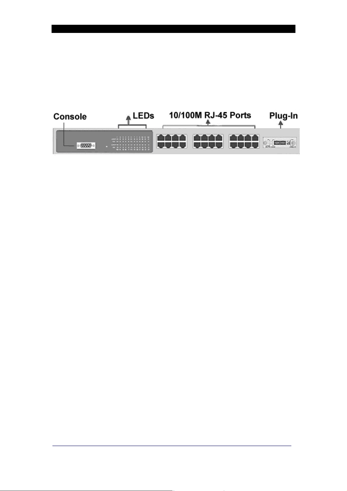
Front Panel
The front panel of the switch has 24 or 16 x RJ-45 Ethernet Ports, an
optional fibre uplink port, a console management port and an array
of LED indicators.
Figure 1 – Switch with optional fibre module (SC Connector) fitted
Ports
!
RJ-45 Ports. These Ethernet RJ-45 ports support both
shielded and unshielded cabling systems. The port
auto-negotiates the 10/100Mbit/s network speed or can be
forced by the console management interface into either
10Mbit/s or 100Mbit/s at either full-duplex or half-duplex.
Each port supports Auto-MDI/MDI-X, which allows either
straight through or crossover cables to be used.
!
Fibre Port Uplink. This optional, field installable plug-in
module provides the fibre link to the distant media converter ,
NIC card or Ethernet switch. Modules are available that
provide support for 100Mb/s Fx (multimode or single mode)
and also dual Gigabit Sx and Lx. See page 8 for order
codes.
!
Console Port. A PC or other RS232 terminal can be
connected to this port to enable detailed management of the
switch. See Page 11 on for details.
Rear Panel
The rear panel contains the 100/240v AC 50/60Hz power socket
and power switch. Note that the fusing is external to the switch. To
disconnect power from the switch remove the plug from rear.
Product Number 0-1591093-x 0-1591047-x Issue 1
© T yco Electronics 2005
Page 5

24 and 16 Port Smart Switch II – User Manual Page 5
Installation
Copper and Fibre Cabling Guidelines
1. The RJ-45 ports can be connected to unshielded twisted pair
(UTP) or shielded twisted pair (STP) cabling systems compliant
with the IEEE 802.3u 100Base TX standard for Category 5. The
cable between the switch and the link partner device (router , hub,
workstation, etc.) must be less than 100 metres long.
2. The 100 Fx fibre link on the optional multi-mode module must use
either 50 or 62.5/125 micron multi-mode fibre cable. You can link
two devices over a distance of up to 2 Km. ST or SC connector
types are supported.
3. The 100 Fx fibre link on the optional single mode module must
use 8/125 or 9/125-micron single-mode fibre cable. You can link
two devices over a distance of up to 30 Km in full duplex mode or
412 m (1,352 ft.) in half-duplex. The single mode module uses
the SC type connector.
4. The dual Gigabit fibre Sx or Lx complies with IEEE802.3z. The
SC type connector is used.
Sx: Module must use either 50 or 62.5/125 micron multimode
fibre cable. Supports distances up to 500 metres.
Lx: Module must use either 8/125 or 9/125-micron single mode
fibre cable. Supports distances up to 10 Km.
5. The console port is an RS232 port and should not be used for
cable distances greater than 20 m.
Product Number 0-1591093-x 0-1591047-x Issue 1
© T yco Electronics 2005
Page 6

24 and 16 Port Smart Switch II – User Manual Page 6
Desktop Installation
1. Locate the switch in a clean, flat and safe position that has easy
access to AC power. Ensure that there is sufficient clearance
around the switch to enable air circulation.
2. Fit the self-adhesive rubber feet to the underside of the switch.
Installing The Switch Into a 19” Rack
1. Identify the required locations and ensure that there is at least
10cm clearance at the front and rear of the switch to allow cables
to be accommodated.
2. Fit the supplied rack mount bracket on both side plates of the
switch using a screwdriver.
3. Locate the switch into the rack and align the holes in the brackets
with holes in the rack vertical strips. Secure the switch using the
supplied bolts.
Installing The Optional Fibre Uplink Module
1. Remove AC power from the switch.
2. Remove the two screws securing the front panel blanking plate.
3. Observe anti-static handling precautions and carefully fit the
plug-in module into the switch and secure it using the
thumbscrews.
Product Number 0-1591093-x 0-1591047-x Issue 1
© T yco Electronics 2005
Page 7

24 and 16 Port Smart Switch II – User Manual Page 7
Completing the Installation
When the switch has been installed as specified above, then the unit
can be configured as detailed below: -
1. Apply AC power to the switch. The green Power LED on the front
panel should light.
2. Connect the Cat. 5/5e twisted pair cables from the network
partner devices to the RJ-45 ports on the front panel of the switch.
When a connection is obtained, the green LK/ACT LED
associated with the port will light.
3. If the fibre uplink is used, then connect the fibre link to the partner
device (media converter , fibre NIC card or fibre switch etc). V erify
that the green Link LED on the fibre module is lit which indicates
that the optical link is valid.
4. If advanced modes such as port-based VLANs are needed, then
use the console port to configure the switch.
5. If legacy devices that do not support auto-negotiation are
connected to the RJ45 ports then it may be necessary to
configure the switch to match the speed and duplex modes of the
partner devices.
6. Note that auto-negotiation can take up to 30 seconds to complete
depending on the partner device.
Product Number 0-1591093-x 0-1591047-x Issue 1
© T yco Electronics 2005
Page 8
24 and 16 Port Smart Switch II – User Manual Page 8
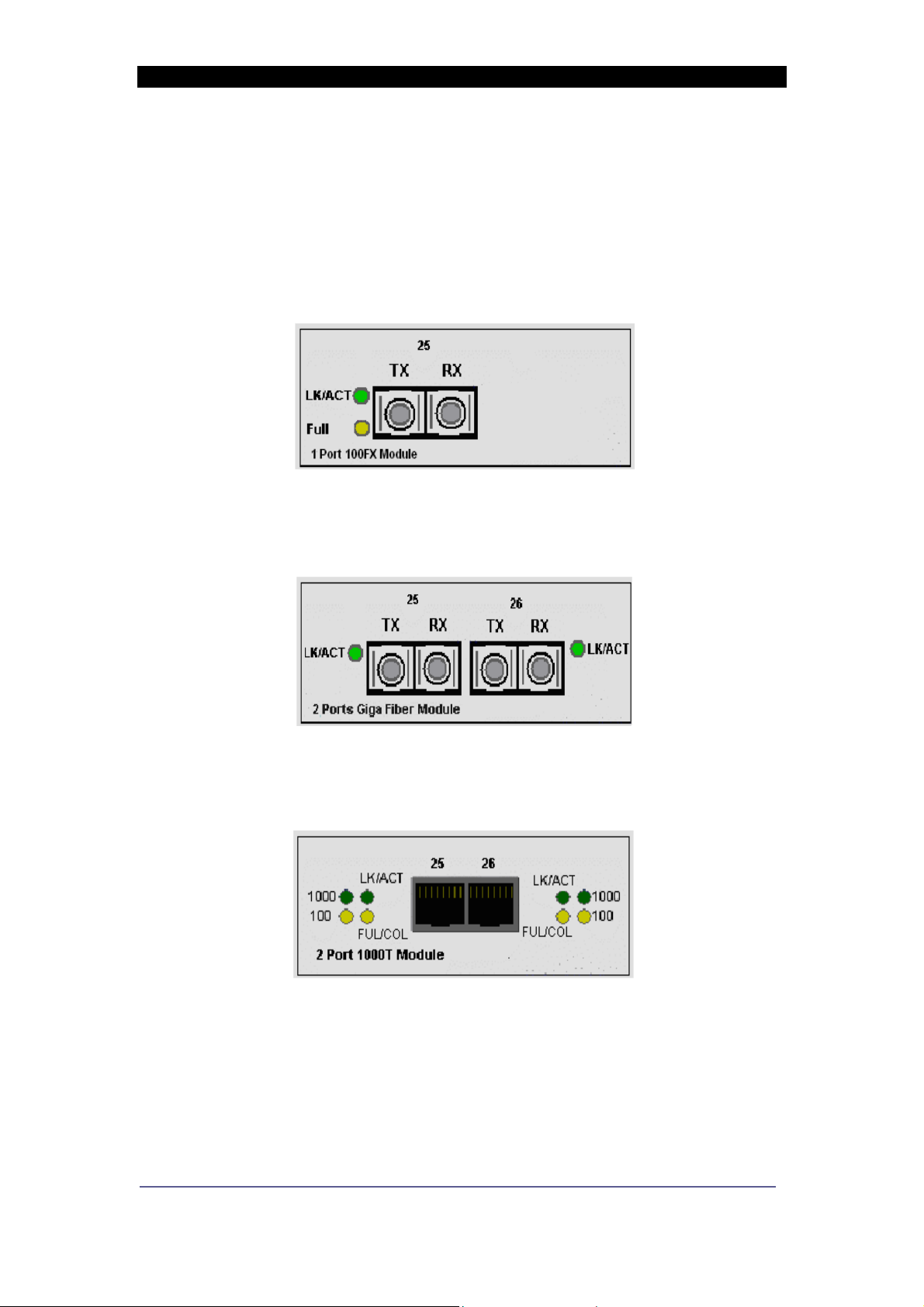
Optional Fibre Uplink Port
This switch can support one single or dual plug-in optical port that is
located on slides in the front panel.
Figure 2 – 100 Fx Plug-in SC option module
Figure 3 Dual Gigabit Plug in module
Figure 4 – Dual Gigabit Copper Module
Product Number 0-1591093-x 0-1591047-x Issue 1
© T yco Electronics 2005
Page 9

24 and 16 Port Smart Switch II – User Manual Page 9
These option modules are installed as described on page 6.
The following plug-in fibre modules are available as field installable
accessories for this switch: -
Product Part Number
100 Fx Module with SC multimode connectors 0-1591094-0
100 Fx Module with ST multimode connectors 0-1591095-0
100 Fx Module with SC singlemode connectors 0-1591096-0
Dual Gigabit Sx Multimode SC connectors 0-1591097-0
Dual Gigabit Lx Singlemode SC connectors 0-1591098-0
Dual Gigabit Copper Module 1000BaseT 2-1591019-0
Table 1 - Uplink Option Ports
Optical Link Wavelength
The 100 Fx optional modules operate at the 1310nm optical
wavelength. The Gigabit Lx Singlemode module operates at
1310nm and the Gigabit Sx multimode module operates at 850nm
optical wavelength.
Optical Link Calculations
The maximum distance between any two fibre optic devices is
determined by a number of factors including optical link loss, the
type and number of patch cords and joints in the link, the launch
power of the transmitter and the sensitivity of the receiver. These
variables make calculating the maximum working distance between
two units quite difficult and so it is best to design networks using
optical loss budgets rather than using just working distance.
Dual Gigabit 1000BaseT copper module
The RJ-45 will auto-negotiate 100Base-TX and Gigabit 1000T
connections. Support for Auto MDI/MDIx is also provided.
It should be noted that Gigabit 1000T (1000Mbps) connection must
use Cat-6 or Cat5-E twisted cable pair cable. If use cat-5 cable is
used then support 100Mbps link speed is available only. The
available link distance is up to 100Meters.
Product Number 0-1591093-x 0-1591047-x Issue 1
© T yco Electronics 2005
Page 10

24 and 16 Port Smart Switch II – User Manual Page 10
Programming The Switch
The switch can be managed using a PC via the front panel RS232
console port and the supplied cable. When the connection between
Switch and PC is complete, turn on the PC and run a terminal
emulation program such as HyperTerminal and configure its
communication parameters to match the following default
characteristics of the console port: -
Com 1 or Com 2
Baud Rate = 9600 bps
Data Bits = 8
Parity = None
Stop Bits = 1
Flow Control = None
Figure 5. Settings the PC communication parameters
Product Number 0-1591093-x 0-1591047-x Issue 1
© T yco Electronics 2005
Page 11

24 and 16 Port Smart Switch II – User Manual Page 11
Press <CR> return key several times to view the main start-up
screen :-
Figure 6 - Main Menu Screen
There are nine key controls in the main menu: -
(1) = Port Status - lists the status and settings of the selected port
(2) = Port Configuration - changes settings on a port
(3) = Trunk configuration - changes trunk settings on the switch
(4) = Trunk status - displays trunk settings of the switch
(5) = QOS settings – changes QoS settings for the switch
(6) = Port Tagging Control - configures the priority tag for the port
(7) = System Control - allows configuration of global switch settings
(8) = VLAN Member Setup - configuration of port based VLANs
(9) = Save - saves the configuration that a user has made
Product Number 0-1591093-x 0-1591047-x Issue 1
© T yco Electronics 2005
Page 12

24 and 16 Port Smart Switch II – User Manual Page 12
Port State
This menu lists the entire port status of the switch. From the main
menu type number 1 and the port status menu will be displayed.
Figure 7 - Port Status Menu
Speed Displays the speed that the port has connected at
Duplex Displays if the port is connected at Full or Half Duplex
Link Displays if the port is connected to active equipment
Flow control Displays if flow control is enabled or disabled on a port
Auto
Negotiation
Trunk Displays if a port belongs to a trunk group
Displays if Auto Negotiation is enabled on a port
Product Number 0-1591093-x 0-1591047-x Issue 1
© T yco Electronics 2005
Page 13

24 and 16 Port Smart Switch II – User Manual Page 13
Port Configuration
This Menu allows for the configuration of all the ports on the switch.
From the main menu select menu item 2 Port Configuration.
The following menu is displayed: -
Figure 8 - Port 1 Configuration
The function keys are listed at the bottom of the page these are: -
U - This moves the cursor up
D - This moves the cursor down
L - This moves the cursor Left
R - This moves the cursor
1 - Moves up a page and shows previous list of ports
2 - Moves down a page and shows next list of ports
Esc - Displays previous menu
Enter - Refreshes information displayed on that page
Space - Changes the state of the selected menu item
N - Causes the switch to refresh and restart auto-negotiation. It is
necessary to select this if any changes have made to the port speed
or duplex mode.
Product Number 0-1591093-x 0-1591047-x Issue 1
© T yco Electronics 2005
Page 14

24 and 16 Port Smart Switch II – User Manual Page 14
The configurable items are shown in the table below :-
Port Selects the port to be configured
Enabled Enables and disables the selected port
Advertisement
Speed
Configures the speed of the selected port or sets
the port for auto negotiation.
Flow control Enables flow control on the selected port
Rx Bandwidth Sets the received bandwidth on the selected port
Tx Bandwidth Sets the transmitted bandwidth of the selected port
Trunk configuration
The Smart Switch II supports up to 8 trunk groups this allows for the
“virtual” combining of network ports to provide a high bandwidth link
between switches. Up to 4 ports can be combined in this way.
To access this menu select 3 from the main menu and the following
menu is displayed: -
Figure 9 Trunking
To enable trunking use the U/D keys to highlight a trunk group and
the Space bar to enable that particular trunk group.
Product Number 0-1591093-x 0-1591047-x Issue 1
© T yco Electronics 2005
Page 15

24 and 16 Port Smart Switch II – User Manual Page 15
Trunk Status
This Menu shows if faults are present on trunks that have been
configured. If 4 is selected from the main menu the following screen
is displayed: -
Figure 10 – Trunk Status screen
If a port that is a member of a trunk group shows no link then an “x”
is displayed next to the trunk group to which the port belongs.
Use the Esc key to return to the previous menu.
Product Number 0-1591093-x 0-1591047-x Issue 1
© T yco Electronics 2005
Page 16

24 and 16 Port Smart Switch II – User Manual Page 16
QOS
This menu can be used to configure the priority of traffic through the
switch.
Three types of QOS are supported: -
1. TOS/Diff Serv Priority -This allows the switch to prioritise traffic
through the switch using the TOS/Diff Serv field contained in the
IP packet.
2. 802.1p Priority - This allows the switch to prioritise traffic through
the switch using the 802.1p priority tag in the MAC header.
3. Port Priority – This allows traffic being received from certain ports
on the switch to be given greater priority through the switch than
that of other ports that are given a lower priority.
By selecting menu option 5 from the main menu the following menu
is displayed: -
Figure 11 – QOS Configuration
The U/D/L/R keys can be used to navigate the menu and the
SPACE bar can be used to change the state of a particular field.
Product Number 0-1591093-x 0-1591047-x Issue 1
© T yco Electronics 2005
Page 17

24 and 16 Port Smart Switch II – User Manual Page 17
It is important that only one method of QOS is enabled on the
switch at any one time. Enabling more than one method could
cause unpredictable prioritisation of traffic.
To enable TOS/Diff Serve priority then first highlight the TOS/Diff
Serve field and press the space bar. This will then show enabled.
To enable 802.1p priority highlight that field and press the space bar .
This will then show enabled.
To enable Port priority then first ensure that TOS/Diff Serv and
802.1p are disabled. Use the navigation keys to move to the cursor
to the Force Port to High Priority Setting section of the menu.
Navigate to the ports that are required to be high priority and press
the space bar. The high priori ty ports will display an x next to them.
The traffic arriving at these priority ports will be assigned a greater
priority than the traffic arriving at ports that have not been assigned
high priority.
The Priority Weighted Ration (High: Low) field is used to set the
precedence ratio between the high and low prioritised traffic.
There are 4 different ratios that can be allocated: -
1:0 -This will force the switch to process all high-prioritised traffic
before it starts to process traffic that has been prioritised as low.
4:1 -This will force the switch to give high priority traffic 4 times more
precedence to that of low priority packets. For every low priority
packet that is processed 4 high priority packets will be processed.
8:1 - This will force the switch to give high priority traffic 8 times
more precedence to that of low priority packets.
16:1 - This will force the switch to give high priority traffic 16 times
more precedence to that of low priority packets.
Product Number 0-1591093-x 0-1591047-x Issue 1
© T yco Electronics 2005
Page 18

24 and 16 Port Smart Switch II – User Manual Page 18
Port Tagging Control
This menu can be used to control the priority tag on Ethernet
packets leaving the switch. This is set on a per port level. If option 6
is selected from the main menu then the following menu is
displayed: -
Figure 12 – Port Tagging Control
There are 4 different settings for each port: Disable – No change to the priority tag will occur. If the tag is set on
incoming packets, then it will remain on any outgoing packet that
leaves the switch via the selected port.
Remove Tag – When a packet leaves this port the priority tag is
removed.
Insert Tag (high priority only) – When a packet leaves this port a
priority tag is inserted for all high priority port packets only.
Insert Tag (All Frame) - When a packet leaves this port a priority
tag is inserted for all high and low priority packets.
System Control
This menu allows configuration of variables that will effect the
Product Number 0-1591093-x 0-1591047-x Issue 1
© T yco Electronics 2005
Page 19

24 and 16 Port Smart Switch II – User Manual Page 19
operation of the entire switch. By selecting item 7 from the main
menu the following screen is displayed: -
Figure 13 - System Control
This menu has 4 separate items. Using the U/D keys each menu
item can be selected and the Space bar can be used to change the
menu item value.
VLAN Function – This enables the VLAN functionality for the
switch. If VLANs are disabled then regardless of the settings made
in the VLAN Member Setup, VLANS will not operate on the switch.
With VLAN Function enabled then VLAN configurations made in the
VLAN Member Setup menu will be implemented and become
active.
Product Number 0-1591093-x 0-1591047-x Issue 1
© T yco Electronics 2005
Page 20

24 and 16 Port Smart Switch II – User Manual Page 20
Switch Name – This item can be used to name the switch. This
name is then shown at the top of each menu. To action this menu
item use the U/D key to highlight the switch name field and press the
Space bar to action the field. A name (maximum 8 characters) can
now be typed. Once the name is typed press the Enter key and the
name will be changed.
Broadcast Storm Filtering – To Enable Broadcast Storm Filtering
highlight item 3 and press the Space bar. With Broadcast Storm
Filtering enabled multicast/broadcast traffic received at a port will be
blocked when a threshold it met. This prevents the switch and
network being overloaded by broadcast traffic, which could cause
loss of connectivity.
Load Factory Defaults – With this menu item selected the switch is
set to a configuration the same as originally shipped from the
manufacturer . Use the U/D keys until cursor is adjacent to the Load
Factory Defaults field and press the Space bar and the following
menu will be displayed: -
Figure 14 - Loading Factory Defaults
Product Number 0-1591093-x 0-1591047-x Issue 1
© T yco Electronics 2005
Page 21

24 and 16 Port Smart Switch II – User Manual Page 21
Select Y and the factory defaults will be loaded.
VLAN Member Setup
The 16 and 24 Smart Switch II supports simple port based VLANs.
These can be configured using the VLAN Member Setup menu. If
Option 8 is selected from the main menu the following menu is
displayed: -
Figure 15 – VLAN Member Setup screen
On initially entering the menu the user is in display mode only, to
insert or delete VLANs then V should be selected and the user will
then be in Edit mode.
Product Number 0-1591093-x 0-1591047-x Issue 1
© T yco Electronics 2005
Page 22

24 and 16 Port Smart Switch II – User Manual Page 22
Adding VLANS
To Insert a VLAN I should be inputted and this will add a new VLAN.
Keep typing I to insert multiple VLANs. To select or deselect port
members use the U/D/L/R to navigate to the relevant port and press
the Space bar. A V indicates a port is a member of a VLAN, as
shown below: -
Figure 16 - Inserting VLAN Members
After all VLANS have been added and ports allocated then press A
to update the VLAN settings and revert the menu back to Display
mode. It is important that VLANs are then enabled in the System
Control Menu (see page 19) or VLAN functionality will not be
active.
Product Number 0-1591093-x 0-1591047-x Issue 1
© T yco Electronics 2005
Page 23

24 and 16 Port Smart Switch II – User Manual Page 23
Save configurations
Any configuration changes made to the switch will need saving to
non-volatile memory to ensure the changes remain if the switch is
power cycled. Select item 9 from the main menu the following
screen is displayed: -
Figure 17 - Save configuration
Type Y and configuration changes will be saved.
Product Number 0-1591093-x 0-1591047-x Issue 1
© T yco Electronics 2005
Page 24

24 and 16 Port Smart Switch II – User Manual Page 24
LED Indicators
The diagnostic LED indicators located on the front panel of the
switch provide real-time information about the switch status. The
following table describes the LED status and meaning.
RJ45 Port
LED Colour Function
Power
LK/ACT
Full
Green Power on
Green Ethernet link pulses are present
Blinks
Off No device is attached or faulty cable
Orange The port is in full-duplex mode
Blinks Collisions in half-duplex mode
Off Port is in half-duplex mode
The port is transmitting or receiving
packets
Optional Fibre Plug-In Module
LED Colour Function
LK/ACT
Green Fibre Connected to another Device
Blinks
The Fibre port is transmitting and
receiving data
Fibre Port
Product Number 0-1591093-x 0-1591047-x Issue 1
FDX/COL
Orange The port is configured for full-duplex
Off The port is configured for half duplex
Table 2 - LED Status and description
© T yco Electronics 2005
Page 25

24 and 16 Port Smart Switch II – User Manual Page 25
Trouble Shooting
Power
1. Verify that the AC power is present and that the external fusing is
correct and compliant with national requirements. The green
Power LED should be lit to indicate that the switch is powered.
Data Problems
1. Ensure that the Ethernet partner device (switch, router, NIC etc)
connected to the RJ-45 port of the switch is set for
auto-negotiation. If this Ethernet partner device does not support
auto-negotiation, then the switch can be programmed to apply
the required speed and duplex modes to match the legacy
partner equipment.
2. If the switch and the partner device cannot auto-negotiate then
the units automatically revert to the lower level of half-duplex
operation. This issue is common to all auto-negotiating Ethernet
devices and symptoms of incorrect negotiation include data
errors and fragmented packets.
3. Auto-negotiation can take up to 30 seconds to complete,
depending on the partner device.
4. Ensure that the switch is not overheating due to obstructed
airflow around the side vents.
Optional Fibre Uplink Module
1. Select the proper fibre cable for your network. The multi-mode
module must use multi-mode fibre cable and the single-mode
module must use single-mode fibre cable. See page 5 for the
supported cable types and installation settings.
2. Ensure that the optical loss budget of the fibre uplink is within the
limits specified on page27. Note that optical patch cables and
other joints and splices can introduce additional optical losses
that reduce the working distance of the fibre link.
Product Number 0-1591093-x 0-1591047-x Issue 1
© T yco Electronics 2005
Page 26

24 and 16 Port Smart Switch II – User Manual Page 26
Product Specification
Standards
Compliance
IEEE802.3 10BASE-T
IEEE802.3u 100BASE-TX/100BASE-FX
IEEE802.3ab 1000BASE-T
IEEE802.3z Gigabit fibre
IEEE802.3x Flow control and Back pressure
IEEE802.3ad Port Trunk
IEEE802.1p Class of service
RJ-45 Port Mode Auto-MDI/MDI-X
Max Forwarding
Rate
14,880 pps Ethernet port (10Mbit/s)
148,800 pps Fast Ethernet port (100Mbit/s)
1488,00 pps Gigabit Ethernet (1000Mbit/s)
LED Indicators Power,
RJ45 Ports: Link Activity, Duplex / Collision
Ethernet LAN
Copper Network
Cable
10Base-T: 2-pair UTP/STP Cat. 3, 4, 5 cable
EIA/TIA-568 100-ohm
100Base-TX: 2-pair UTP/STP Cat. 5 cable
EIA/TIA-568 100-ohm
Dimensions 440mm x 165mm x 44mm (W x D x H)
Operating
0ºC to 45ºC (32ºF to 113ºF)
Temperature
Operating
10% to 90% (Non-condensing)
Humidity
Power Supply Internal 100v to 240v AC, 50/60Hz auto-
ranging, externally fused.
Power
20 Watts (Max.)
Consumption
EMI Safety FCC Class A, CE, UL, cUL, CE/EN60950
Product Number 0-1591093-x 0-1591047-x Issue 1
© T yco Electronics 2005
Page 27

24 and 16 Port Smart Switch II – User Manual Page 27
Optical Port Specifications
Optical Transceiver TX power
100Mbps Multi-mode
-19dBm -31dBm 12dBm
Transceiver
100Mbps single mode
-15dBm -34dBm 19dBm
Transceiver (30KM)
Gigabit Transceiver (SX,
-9.5dBm -17dBm 7.5dBm
multi--mode fibre)
Gigabit Transceiver (LX,
-9.5dBm -20dBm 10.5dBm
single-mode Fibre)
Table 3 - Optical Specifications
RX
sensitivity
Power
Budget
Product Number 0-1591093-x 0-1591047-x Issue 1
© T yco Electronics 2005
Page 28

24 and 16 Port Smart Switch II – User Manual Page 28
Table Of Contents
INTRODUCTION..................................................................................................................................1
PACKAGE CONTENTS .......................................................................................................................2
FEA TURES: - ........................................................................................................................................3
TECHNICAL SUPPORT AND SERVICE...........................................................................................3
REAR PANEL ........................................................................................................................................4
INSTALLATION....................................................................................................................................5
OPTIONAL FIBRE UPLINK PORT...................................................................................................8
LED INDICATORS..............................................................................................................................24
TROUBLE SHOOTING......................................................................................................................25
PRODUCT SPECIFICATION............................................................................................................26
Product Number 0-1591093-x 0-1591047-x Issue 1
© T yco Electronics 2005
Page 29

24 and 16 Port Smart Switch II – User Manual Page 29
24 and 16 Port Smart Switch II – User Manual Page 29
Product Number 0-1591093-x 0-1591047-x Issue 1
Product Number 0-1591093-x 0-1591047-x Issue 1
© T yco Electronics 2005
© T yco Electronics 2005
 Loading...