

Tyco Electronics 10/100Mbit/s Ethernet Media Converters, 0-1591024-x, 0-1591026-x, 0-1591028-x, 0-1591030-x User Manual
...Page 1

10/100Mbit/s
Ethernet Media Converters
-
Product User Guide
Introduction
This Tyco Electronics/AMP Netconnect auto-negotiating Fast
Ethernet Media Converter translates between 10/100Base-TX
copper and 100Base-FX fiber cabling. The converter can be either
rack mounted in a 19” Chassis Unit or used as a standalone unit.
The Media Converter enables you to extend the distance of your
10/100BaseTX Ethernet network up to 2 kilometers for multi-mode
fiber or up to 30 kilometers for single-mode fiber. SC, ST and MT-RJ
optical multimode fiber connectors are available.
This range of media converters also includes a WDM ( Wavelength
Division Multiplexing ) Converter. This has exactly the same
functionality as the standard converters but the WDM technology
that combines the transmit (TX) and receive (RX) lines onto a single
fiber, which reduces cabling cost.
A pair of WDM converters ( wavelength 1310 and 1550 nm ) should
be installed at either end of the single fiber cable.
(AP) PL0336 Issue 1.36
Page 2
Fast Ethernet Media Converter
Package Contents
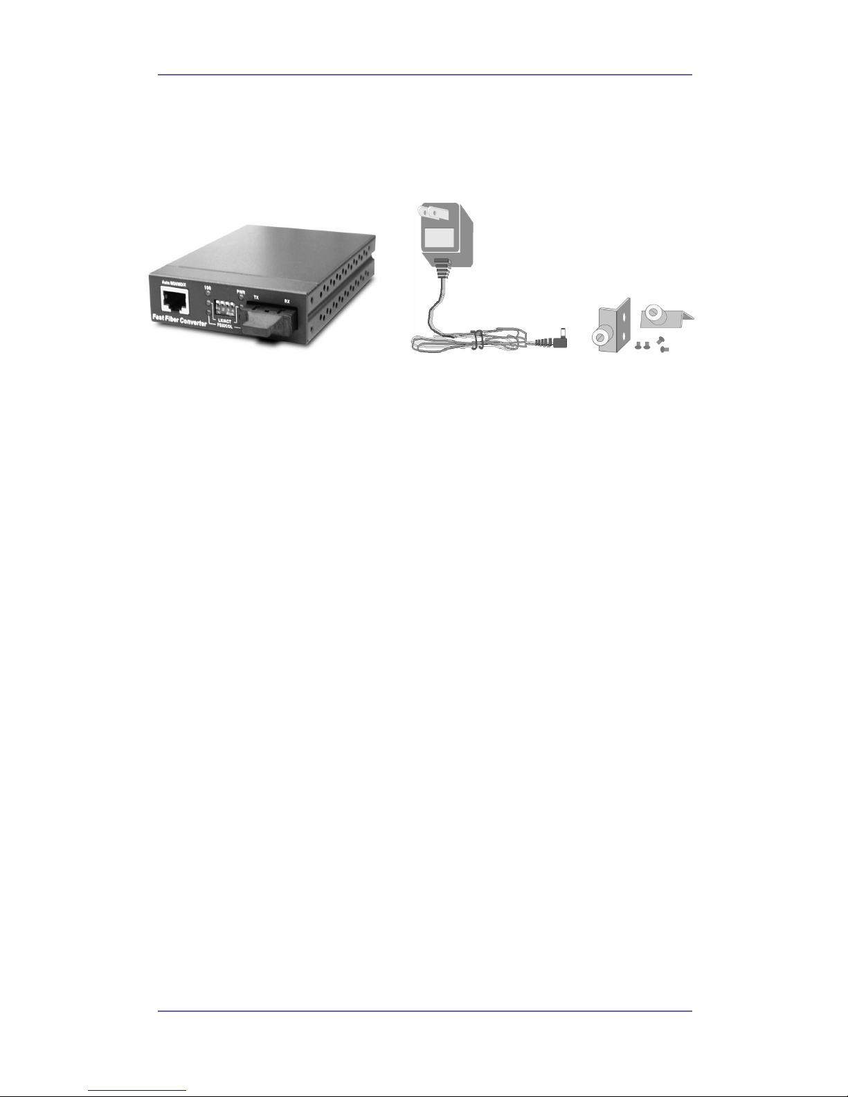
Unpack the contents and verify them against the items below.
Figure 1 – Items in the packing box
If any item is damaged or missing, please contact your dealer.
Features
n Converts between Ethernet UTP and fiber-optic cabling
n Meets IEEE 802.3, .3u and .3x Ethernet standards
n One RJ-45 shielded/UTP port with Auto MDI/MDI-X
eliminates the need for cross-over LAN cables.
n One fiber Ethernet port with an SC, ST or MT-RJ
connector for 100Base-FX
n Supports 10/100Mbit/s Auto-negotiation on UTP port
n Supports 100Mbit/s Full duplex for non
auto-negotiating services
n Supports Link Loss Forwarding to signal fault events
n Uses store-and-forward switching to separate the two
collision domains
n Integral 1K MAC address table automatic learning
n Supports back-pressure & flow control
n DIP-switches to set the operation mode for the UTP and
Fiber port
n Fiber connectivity up to 2Km (multi-mode) or 30 Km
(single-mode). WDM technology for single-mode only.
Tyco Electronics Page 2
Page 3

Fast Ethernet Media Converter
n 3 LEDs for the UTP port:- Speed, UTP Link Activity, Full
Duplex/Collision
n 2 LEDs for the Fiber port:- Link Activity and Full
Duplex/Collision
n External AC/DC power adapter
n Stand-alone or mountable in 19” Converter Chassis
n FCC Class A, CE mark certification
Technical Support and Service
If you require technical advice for these products, please see the
FAQ pages on the web address http://www.lan-electronics.com
If you still have problems, please contact us using the support form
located on the above web site.
If you have a faulty unit then please contact us through the web site
to arrange for a replacement unit. The faulty unit must be returned to
us as part of the replacement agreement.
Tyco Electronics Page 3
Page 4
Fast Ethernet Media Converter
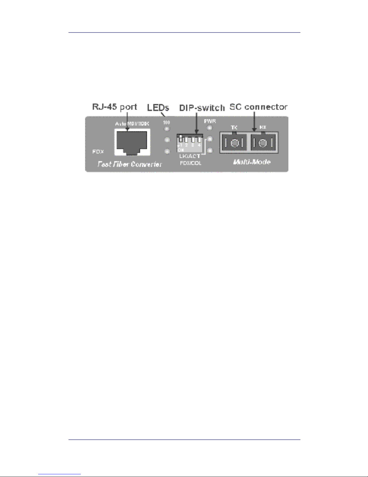
Front Panel
The front panel of the media converter has an RJ-45
Shielded/Unshielded Ethernet Port, 6 LED Indicators and a fiber
Ethernet 100Base-FX Port.
Figure 2 - Media Converter with SC Connector
Note that media converters with SC, ST and MT-RJ fiber optic
connectors are also available. See page 13 for details of order
codes.
Ports
n RJ-45 Port. This Ethernet RJ-45 supports both shielded
and unshielded cabling systems. The port either
auto-negotiates the 10/100Mbit/s network speed or can be
forced by DIP switch 1 into a 100Mbit/s full-duplex mode. In
addition, the port uses auto MDI/MDIX detection which
eliminates the need for cross-over cables when connecting
to LAN switches or workstations.
n Fiber Port. This port is for the 100 Base-FX connection to
the distant media converter, NIC card or Ethernet switch.
The port operates in either full duplex or half duplex modes
depending on the setting of DIP switch 2.
Tyco Electronics Page 4
Page 5

Fast Ethernet Media Converter
Rear Panel
The rear panel contains a power socket. This power socket accepts
DC 9V voltage and minimum 0.7A supplied current.
Installation
Copper and Fiber Cabling Guidelines
1. The RJ-45 port can be connected to unshielded twisted pair
(UTP) or shielded twisted pair (STP) cabling systems. The cable
must comply with the IEEE 802.3u 100Base TX standard for
Category 5. The cable between the converter and the link partner
device (switch, hub, workstation, etc.) must be less than 100
meters (328 ft.) long.
2. The fiber link on the multi-mode converter must use either 50 or
62.5/125 micron multi-mode fiber cable. You can link two
converter devices over a distance of up to 2 kilometres.
3. The fiber link on the single-mode converter must use 8/125 or
9/125 micron single-mode fiber cable. You can link two
converters over a distance of up to 30 kilometers in full duplex
operation (DIP-Switch 2 = off). If the converter is operated in the
half-duplex mode (DIP-Switch 2 = on), the recommended
maximum distance is reduced to 412 metres (1,352 ft.)
Installing Media Converters into the Chassis
Follow the steps below to install converters into the 19”
rack-mountable chassis (part number 1-1591032-1).
1. Remove the blank plate from the chassis using a screwdriver. Put
the blank plate aside.
2. Open the rackmount bracket kit which contains two rackmount
brackets with thumbscrews and four securing screws.
3. Attach a rackmount bracket on both sides of the media converter
using a screwdriver.
Tyco Electronics Page 5
Page 6

Fast Ethernet Media Converter
Figure 3 - Fitting the rack-mount brackets
4. Install the converter by inserting it into the chassis guides and
carefully sliding it in until the converter is fully located.
Figure 4 - Inserting the media converter into the chassis
5. Gently push the thumbscrews in and gently turn clockwise to
tighten.
Completing The Installation
When the converter has been installed as specified above, then the
system can be configured as detailed below:-
Tyco Electronics Page 6
Page 7

Fast Ethernet Media Converter
1. Select the appropriate length Cat. 5/5e twisted pair cable, then
connect one end of the cable to the RJ-45 connector on the
media converter and the other end of twisted pair cable to the
RJ-45 connector on the partner 10/100Mbit/s Ethernet partner
device.
2. Connect one end of a fiber cable to the ST/SC/MT-RJ connector
on the converter and the other end of the fiber cable to the
ST/SC/MT-RJ connector on the remote 100 Base-FX device,
typically another media converter.
3. Apply the DIP-Switch settings as detailed on page 8.
4. Attach the power adapter DC jack to the converter and verify that
the Power (PWR) LED on the front panel lights up.
5. Verify that UTP LK/ACT LEDs light up when the UTP cable
connection is correct, and Fiber LK/ACT LED is either green to
show presence of a valid fiber link or blinks to indicate traffic
activity.
Tyco Electronics Page 7
Page 8
Fast Ethernet Media Converter
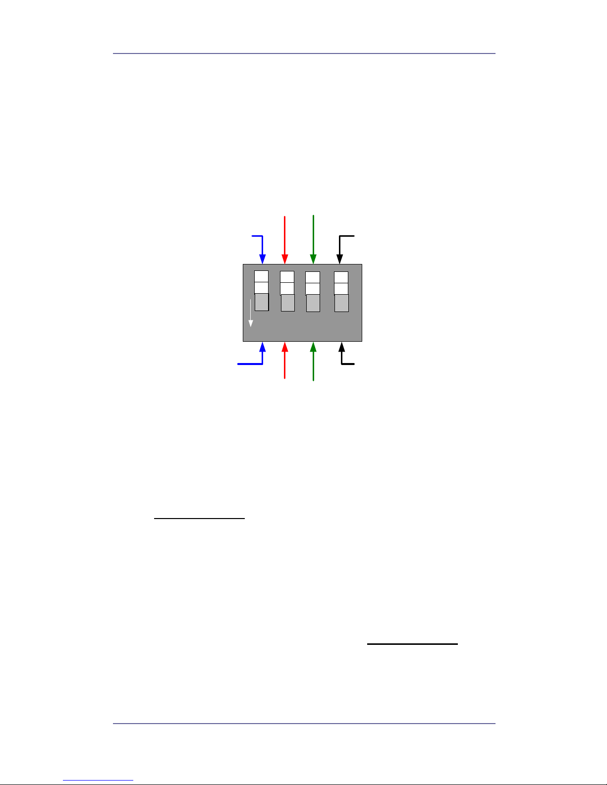
DIP-Switch Settings
The configuration switch is used to set the line speed of the UTP
port, the operation mode for the Fiber port, Link Loss Forwarding
and the setting of “pure” or “switching” operation of the converter.
The default switch setting is UTP = Auto-negotiate, Fiber = Full
Duplex, LLF =disable and converter in switched mode.
1
ON
S/UTP Auto-Negotiate
S/UTP 100Mbit/s
Full Duplex
Fibre 100Mbit/s
Half Duplex
Fibre 100Mbit/s
Full Duplex
2
Pure Converter Mode
Switching Converter
Mode
Link Loss
Disable
Link Loss
Enable
34
Figure 5 – Default DIP Switch Settings
UTP Auto-negotiation
With DIP-switch 1 in the OFF (up) position, the converter will
try to auto-negotiate with its partner. If the partner device does
not support auto-negotiation, then the converter will detect
either 100Mbit/s or 10Mbit/s and operate in the half duplex
mode. (Default setting
).
100M Full-duplex
With DIP-switch 1 in the ON (down) position, the converter
forces the UTP port to 100Mbit/s full duplex operation.
Fiber Full-duplex
With DIP-switch 2 in the OFF (up) position, the fiber port will
be configured in 100Mbit/s full-duplex mode (Default setting
).
Fiber Half-duplex
With DIP-switch 2 in the ON (down) position, the fiber port is
configured to 100Mbit/s half-duplex mode .
Tyco Electronics Page 8
Page 9

Fast Ethernet Media Converter
Link Loss Forwarding Disable
With DIP-switch 3 in the OFF (up) position, the converter will
not operate in the Link Loss Forwarding mode. In this case,
fault events are not signaled across the link or to the distant
unit. (Default setting
).
Link Loss Forwarding Enable
With DIP-switch 3 in the ON (down) position, the converter
will enable the Link Loss Forwarding function which can be
used to extend the fault status over the link to the distant unit.
Switch converter mode
With DIP-switch 4 in the OFF (up) position the converter will
operate in store and forward switch converter mode. In this
mode any illegal frames will be rejected by the converter
(Default setting
).
Pure converter mode
With DIP-switch 4 in the ON (down) position the converter will
operate in “pure “ converter mode. In this position the
converter will transmit the data as soon as it is received and so
the traffic will flow quicker than when in switch converter
mode. For such applications the converter should operate in
100M operation.
Notes:-
§ After changing the DIP-switch setting, the unit needs to be reset
by power-cycling before the switch changes can take effect.
Tyco Electronics Page 9
Page 10

Fast Ethernet Media Converter
Link Loss Forwarding (LLF)
It is common in networking for resilient secondary routes to be
adopted so if the main route is broken the second route becomes
active and automatically starts to pass traffic third party equipment
uses spanning tree to implement this resilient function. It is
important therefore that accurate diagnosis of a route failure by the
connected network equipment takes place. To support this signaling,
link loss forwarding is provided by the converter.
If DIP – switch 3 is set to ON then LLF is enabled.
When enabled disconnecting the fiber then the RJ45 port will lose
link status. When disconnecting the copper JR45 port the optical
port will lose link status.
Maximum Frame Size
The maximum frame size that the 10/100 media converter can
support when in “switch” converter mode is 1589 bytes including
CRC and tagged VLAN extension.
All Packets greater than 1589 bytes are discarded and so will not
pass across the link. When in “pure” converter mode packets will not
be rejected regardless of size.
Tyco Electronics Page 10
Page 11
Fast Ethernet Media Converter
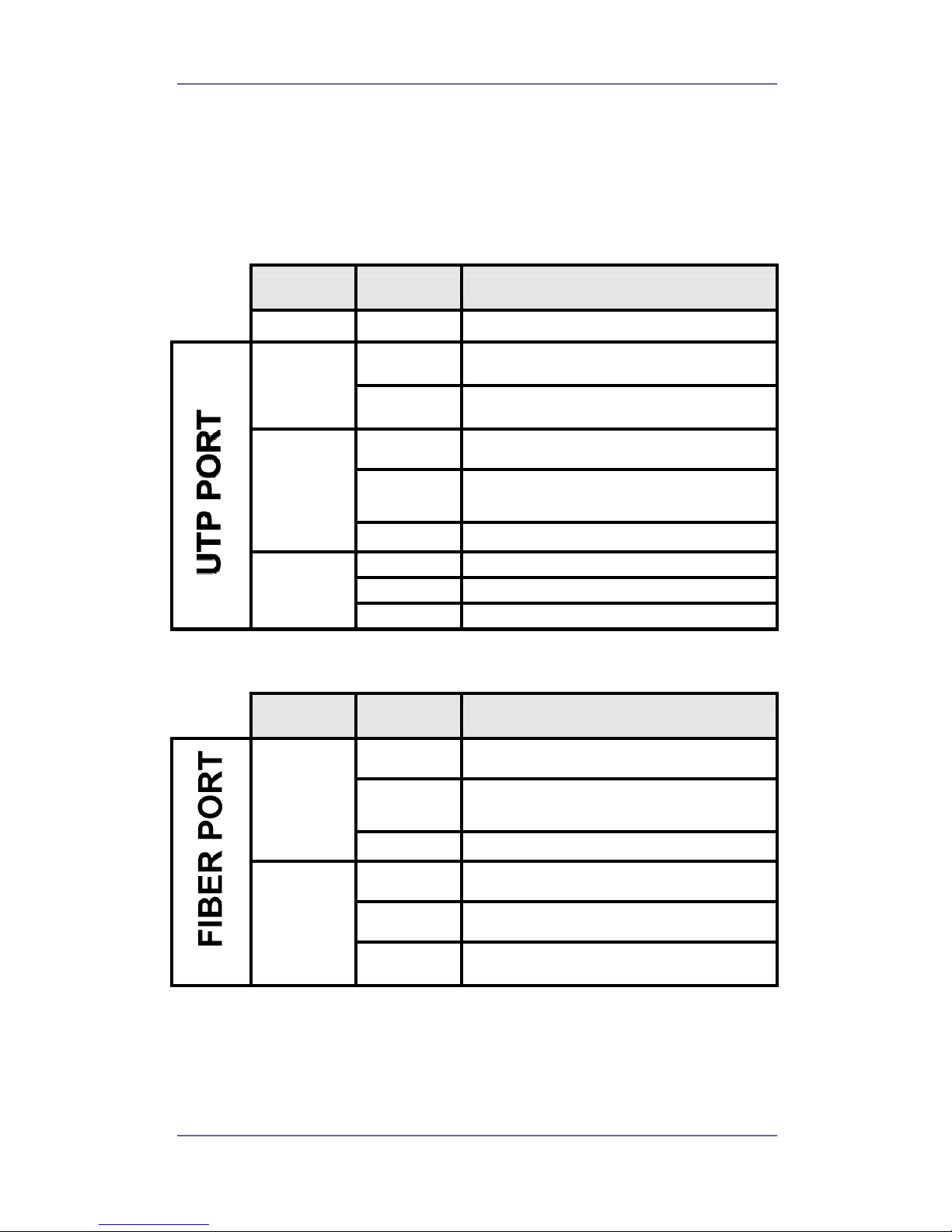
LED Indicators
There are 6 diagnostic LEDs located on the front panel of the media
converter. These LEDs provide real-time information of system
status. The following table provides a description of the LED status
and meaning.
LED Color Function
PWR Green Power on
Green
The UTP port is operating in 100Mbps
mode.
100
Off
The UTP port is operating in 10Mbps
mode or no device attached
Green Link pulses are present
Blinks
The unit is transmitting or receiving
packets
LK/ACT
Off No device attached or faulty cable
Orange The port is in full-duplex mode
Blinks Collisions in half-duplex mode
FDX/COL
Off The port is in half-duplex mode
LED Color Function
Green Link pulses are present
Blinks
The unit is transmitting or receiving
packets
LK/ACT
Off No device attached or faulty cable
Orange The port is in full-duplex mode
Blinks Collisions in half-duplex mode
FDX/COL
Off
The port is in half-duplex mode or no
device is attached.
Table 1 - LED Status and description
Tyco Electronics Page 11
Page 12

Fast Ethernet Media Converter
Trouble Shooting
Power
1. Only use the correct AC/DC power adapter (DC 9v, 0.7 Amp with
the positive to the center pin of the power connector). Do not use
a power adapter with DC output voltage higher than 9V, or with
the wrong polarity as this will damage the converter.
Fiber Link
1. Select the proper fiber cable for your network. The multi-mode
converter must use multi-mode fiber cable and the single-mode
converter must use single-mode fiber cable. See page 5 for the
supported cable types and installation settings.
2. Ensure that the optical loss budget of the fiber link is within the
limits specified on page 14. Note that optical patch cables and
other joints and splices can introduce additional optical losses
that reduce the available working distance of the fiber link.
Data Problems
1. Ensure that the Ethernet partner device (switch, router, NIC etc)
connected to the UTP port of the converter is set for
auto-negotiation. If this Ethernet partner device does not support
auto-negotiation, then you need to program that device to
operate at 100Mbit/s half duplex or 10Mbit/s half duplex. This is
because the media converter and the Ethernet device will not be
able to correctly negotiate and will then revert to the lower level of
half-duplex operation.
This issue is common to all auto-negotiating Ethernet units and
symptoms of failed negotiation include data errors and
fragmented packets.
2. Auto-negotiation can take up to 30 seconds to achieve,
depending on the connected partner device.
3. Check the configuration of the front panel DIP switches. The
default setting for the fiber link is Full Duplex and the default
setting for the UTP port is Auto-Negotiate. Link Loss Forwarding
is disabled by default. See page 8 for DIP switch settings.
Tyco Electronics Page 12
Page 13

Fast Ethernet Media Converter
4. Ensure that the media converter is reset by removing power after
either of the DIP switch settings have been changed.
If you still have problems and need further advice, please see
Technical Support section on page 3 to obtain more information.
Product Part Numbers
The products in this family of 10/100Mbit/s Ethernet media
converters are:-
Product Part Number
Converter with SC multimode connectors 0-1591024-x
Converter with ST multimode connectors 0-1591026-x
Converter with MT-RJ multimode connector 0-1591028-x
Converter with SC singlemode connectors 0-1591030-x
WDM Converter with SC singlemode 1550nm 0-1591029-x
WDM Converter with SC singlemode 1310nm 0-1591031-x
Where –x is the country code. Consult dealer for precise codes.
Tyco Electronics Page 13
Page 14

Fast Ethernet Media Converter
Optical Fiber Specifications
The standard converters operate at the 1310nm optical wavelength
for both the multimode and singlemode media converters.
The WDM converters operate at the 1310nm and 1550nm optical
wave length simultaneously .
The fiber size used for multimode links is 50/125 or 62/125 micron.
The fiber size used for singlemode links is 8/125 or 9/125 micron.
The maximum distance between any two fiber optic devices is
determined by a number of factors including optical link loss, the
type and number of patch cords and joints in the link, the launch
power of the transmitter and the sensitivity of the receiver. These
variables make calculating the maximum working distance between
two converters quite difficult and so it is best to design networks
using optical loss budgets rather than using just working distance.
Fast Ethernet
Converter Type
Avg. Launch
Power dBm
Avg. Power
Loss Budget
dB
Avg.
Sensitivity
dBm
Multimode Converter (SC)
-18
dB
12d
Bm -30dB
Multimode Converter (ST)
-18
dB
12
dBm -30dB
Multimode Converter (MT-RJ)
-16
dB
14
dBm -30dB
Singlemode Converter (SC)
-6
dB
28
dBm -34dB
Table 2 - Optical Specifications
Tyco Electronics Page 14
Page 15
Fast Ethernet Media Converter
Product Specification
LAN Standards
Compliance
IEEE 802.3 10Base-T Ethernet
IEEE 802.3u 100 BASE-TX Fast Ethernet
IEEE 802.3u 100 Base-FX Fast Ethernet
ANSI/IEEE standard 802.3 N-way
Auto-Negotiation
Max Forwarding
Rate
14,880 pps Ethernet port (10Mbit/s)
148,800 pps Fast Ethernet port (100Mbit/s)
LED Indicators Device: Power.
UTP: Speed, Link Activity,
Full Duplex/Collision
Fiber: Link Activity, Full Duplex/Collision
Ethernet LAN
Copper Network
Cable
10Base-T: 2-pair UTP/STP Cat. 3, 4, 5 cable
EIA/TIA-568 100-ohm
100Base-TX: 2-pair UTP/STP Cat. 5 cable
EIA/TIA-568 100-ohm
Fiber Link Max.
Distance
ST/SC/MT-RJ Multi-mode:
Half-duplex:412m, Full-duplex: 2Km
SC Single-mode:
Half-duplex:412m, Full-duplex: 30 Km.
WDM 20Km
Dimensions 118mm x 84mm x 25mm (L x W x H)
Weight 316 ~ 318g depending on fiber connector
Operating
Temperature
0ºC to 45ºC (32ºF to 113ºF)
Operating
Humidity
10% to 90% (Non-condensing)
Power Supply External Power Adapter DC 9V, 0.7 A
Power
Consumption
4 Watt. (Max.)
EMI FCC Class A, CE Mark
Table 3 - Product Specifications
Tyco Electronics Page 15
 Loading...