

Page 1
The WS4933 is designed to monitor the CO gas level
in residential dwellings and give early warning before
potentially dangerous levels are detected. This device
is intended for use with a compatible wireless alarm
system.
The detector consists of an electrochemical carbon
monoxide sensor assembly coupled to a wireless transmitter. The Wireless Carbon Monoxide Alarm communicates with the control panel and can send alarm,
tamper and battery condition messages to the system’s
receiver.
Caution: The detector expiry date is stamped on the
detector. After the expiry date, the detector should
not be used - do not wait for end-of-life indication!
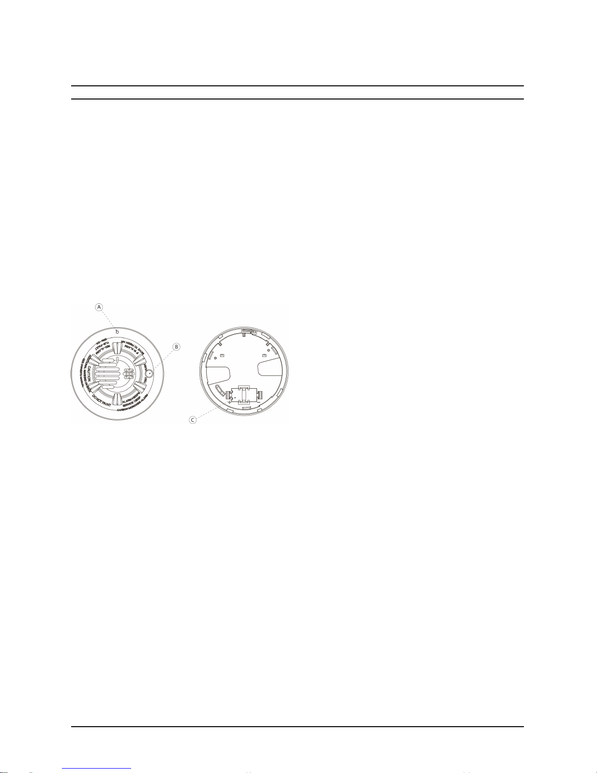
Figure 1: WS4933 Wireless CO Detector
Legend
A. Alarm LED (see Table 1 for LED indications)
B. Test/Hush button
C. Battery compartment
CAUTION: Unauthorized removal of the unit
from the bracket will initiate a tamper alert.
Warnings:
The WS4933 Series wireless Carbon Monoxide
detector shall be installed and used within an environment that provides the pollution degree max 2 and
overvoltages category II in NON HAZARDOUS
LOCATIONS, indoor only. The equipment is
designed to be installed by SERVICE PERSONS
only; (SERVICE PERSON is defined as a person having the appropriate technical training and experience
necessary to be aware of hazards to which that person may be exposed in performing a task and of measures to minimize the risks to that person or other
persons.)
Failure to properly install, test and maintain a CO
detector may cause it to fail, resulting in loss of life.
Installation of the CO detector should not be used as a
substitute for proper installation, use and maintenance
of fuel burning appliances, including appropriate ventilation and exhaust systems.
This carbon monoxide detector is designed for indoor
use only. Do not expose to rain or moisture. Do not
knock or drop the detector. Do not open or tamper
with the detector as this could cause malfunction. The
detector will not protect against the risk of carbon
monoxide poisoning if not properly installed.
CAUTION: This device will only indicate the presence of carbon monoxide gas at the sensor. Carbon
monoxide gas may be present in other areas. This carbon monoxide alarming device is designed to detect
carbon monoxide gas from ANY source of combustion. It is NOT designed to detect smoke, fire or
other gases unless the product has been investigated
and determined to comply with applicable requirements.
Installation Instructions
Battery Installation
To replace the battery:
1. Remove the detector from its mounting base by
twisting it counterclockwise. Remove and dispose of the battery according to your local regulations.
2. To ensure proper power-down sequence, wait a
minimum of 20 seconds before installing the
new battery.
3. Install a new 3-volt CR123A Panasonic Lithium
battery in the battery compartment observing
correct polarity. If the battery is incorrectly
inserted, remove gently with a non-conductive
tool and correctly reinsert.
4. Reinstall the detector onto the mounting base by
turning it clockwise.
5. After the power-up sequence, the green LED
should blink once every 12 seconds to indicate
normal operation. If the battery is not installed
correctly, the detector will not operate and the
battery may be damaged.
Enrollment
At the alarm control panel, program the 6-digit serial
number of the WS4933 (located on the back of the
detector). Please refer to your control panel installation manual for details.
Selecting a Location
Selecting a suitable location is critical for the CO
detector. The Consumer Product Safety Commission
(CPSC) recommends to use at least one CO detector
per household, located as near as possible to sleeping
areas of the home, because the human body is most
vulnerable to the CO gas effect during sleeping hours.
1
WS4933 (433MHz) Series Wireless Carbon Monixide
Detector
Installation and Operating Instructions
Read these instructions thoroughly before installation and use of the WS4933
Page 2
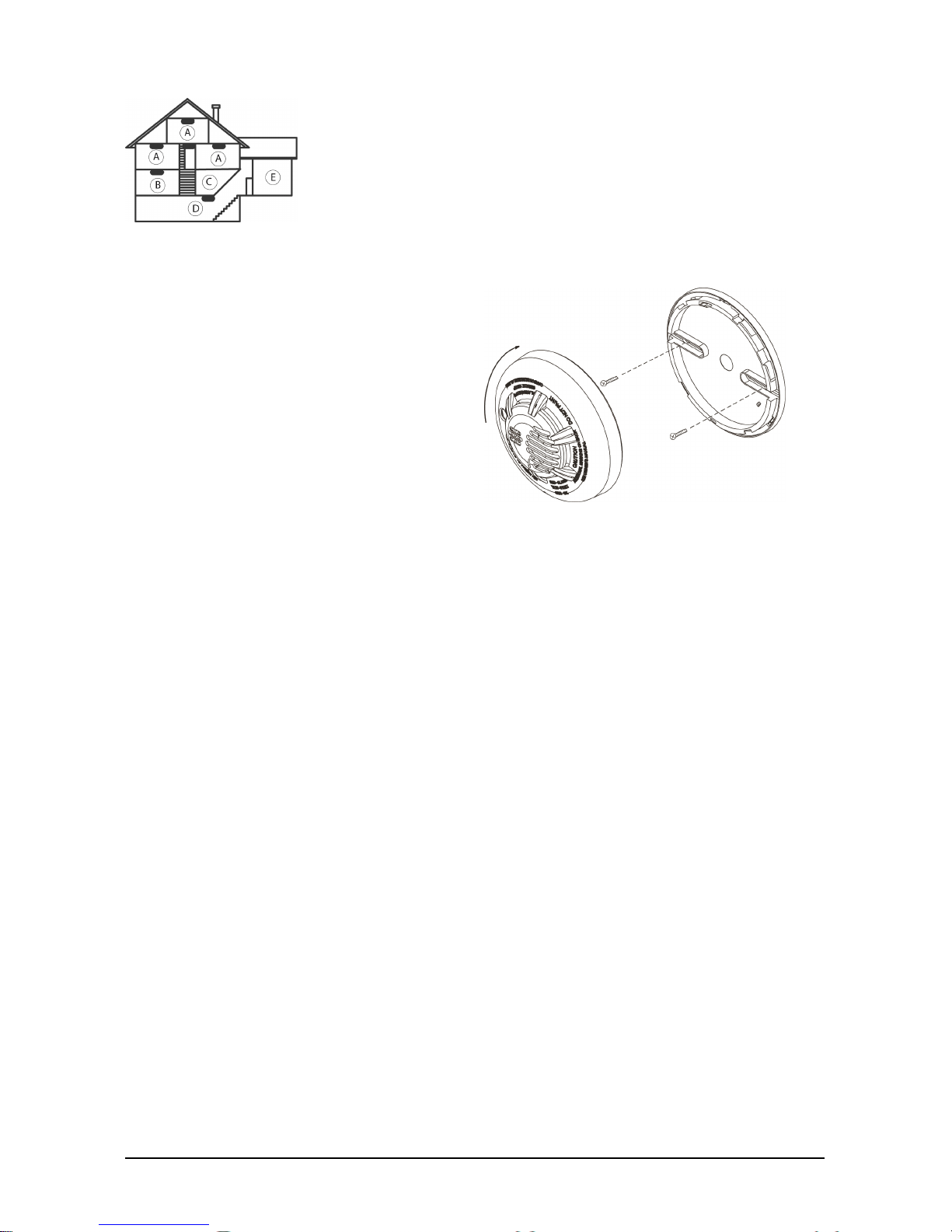
Figure 2: CO Detector Placement
Legend
A: Bedroom
B: Living Room
C: Kitchen
D: Basement
E: Garage
For added protection, install additional CO detectors in every separate bedroom and on every level of
your home. If your bedroom hallway is longer than
14 meters (40 feet), install a CO detector at BOTH
ends of the hallway. Install an additional detector 6
meters (20 feet) away from the furnace or fuel
burning heat source.
For maximum protection, the detector should also
be located outside primary sleeping areas or at each
level of your home. Mount the detector on a firm
wall or ceiling.
DO NOT install CO detectors:
l In locations where temperature may be below
0ºC (14ºF) or above 40ºC (104ºF).
l In locations where humidity is below 10% or
above 93% RH non-condensing.
l Near paint thinner fumes.
l Near air conditioners, furnaces, stoves, fire-
places and any other ventilation source that may
interfere with CO gas entering the detector.
l In locations where furniture or draperies may
obstruct the air flow.
l In exhaust streams from gas engines, vents,
flues or chimneys.
l Where dirt or dust could collect and block the
sensor and prevent it from working.
l In locations that can be reached by children.
l In turbulent air from ceiling fans.
l In close proximity to an automobile exhaust pipe
- this will damage the detector.
Mounting
The detector can be mounted on a wall or ceiling.
For EN approved sites, only ceiling installation is
allowed.
The WS4933 must be mounted with its bracket
(when it is attached to its bracket the tamper switch
is pressed and the detector automatic reset is performed).
1. Refer to the diagram below and install using
screw locations as required. Maneuver the
base so the screws are at the elbow of the
screw slots and secure.
2. Fit the detector inside the mounting bracket by
aligning it as shown in Figure 3 (detector’s
alignment notch should be slightly offset from
the mounting bracket tamper release tab), then
turn the detector in a clockwise direction until
it clicks into place.
3. Test the detector after completing the installation (as described in the TESTING THE
DETECTOR section of this manual) and
refer to the alarm control panel installation
manual for additional information concerning
the use of wireless devices.
Figure 3: Mounting the Detector
Tamper Protection
The WS4933 includes a tamper resistant feature
that prevents removal from the mounting base
without the use of a tool. To engage the tamper resistant feature, cut the small plastic tab located on
the mounting bracket and then install the detector.
To remove the detector from the base once it has
been made tamper resistant, use an appropriate
screwdriver to depress the square tamper release
tab located on the skirt of the mounting bracket and
turn the detector counterclockwise.
Owner's Instructions
Testing the Detector
Note: Before testing, notify the central station.
Test the detector by pressing the Test/Hush button.
The red LED flashes and the sounder emits a temporal 4 pattern. The keypad indicates that the
detector is in alarm.
Maintenance
Press the detector's TEST/Hush button once every
week to ensure proper operation of the detector.
When low battery alarm exists (see specifications)
immediately replace the battery.
Once a month, use a vacuum cleaner to keep the air
vents free of dust.
2
Page 3

Audible and Visual Indications
The tricolored LED (green, yellow, red) and a
sounder on the detector provide local visual and audible indication of the detector’s status as listed in
Table 1.
Status LEDs
Sounder (does
not pulse the
sounder and
LED con-
currently)
Radio Sig-
nalling
Normal
Green
flash
every 12
seconds
Off
Normal
(none)
Alarm/Test
Red flash
every 12
seconds
ANSI S3.41
temporal 4
(press button
to hush for 5
minutes)
Alarm
Detector
Trouble
Yellow
flash
every 6
seconds
One 100ms
chirp every 45
seconds
Fault
Low
Battery
Yellow
flash
every 12
seconds
One 100ms
chirp every 45
seconds (press
button to hush
for 12 hours)
Low
battery
Detector
End of
Life
Yellow
flash
every 23
seconds
One 100ms
chirp every 45
seconds
Fault
Powerup
Green,
yellow,
red flash
sequence
every 12
seconds
One 100ms
chirp at end
of power-up
sequence
None
Tamper
Green,
yellow,
red flash
sequence
every 12
seconds
Off Tamper
Table 1: Detector Status and Indication
Specifications
End of life:
7 years (see date stamped on back
of detector)
Operating
frequency:
433MHz
Audible
signal (temp
4 tone):
85 dBA min. in alarm (at 10ft
(3m))
Operating
current:
10 μA
Temperature
range:
0°C to 40°C (32°F to 104°F)
Operating
humidity
range:
15% to 95% Relative Humidity,
non-condensing
Transmitted
messages:
CO gas alarm, low battery, tamper,
trouble message as a result of
sensor end of life or sensor trouble,
supervision.
Power
source:
One 3-volt CR123A Panasonic
Lithium Battery (included)
Battery
supervision:
Automatic transmission of battery
status data as part of any
transmitted message.
Battery life
expectancy:
5 years (under typical use). Note:
Constant exposure to temperature
or humidity extremes may reduce
battery life.
Low battery
threshold:
2.3 V
You should know about Carbon Monoxide.
Carbon monoxide, also known as "CO" by the chemical form, is considered to be a highly dangerous
poisonous gas, because it is colorless, odorless or
tasteless and very toxic. In general, biochemistry
phenomena have shown that the presence of CO gas
inhibits the blood's capacity to transport oxygen
throughout the body, which can eventually lead to
brain damage. In any enclosed space (home, office)
even a small accumulation of CO gas can be quite
dangerous. Although many products of combustion
can cause discomfort and adverse health effects, it
is CO gas which presents the greatest threat to life.
Carbon monoxide is produced by the incomplete
combustion of fuels such as natural gas, propane,
3
Page 4

heating oil, kerosene, coal, charcoal, gasoline, or
wood. The incomplete combustion of fuel can occur
in any device which depends on burning for energy
or heat such as furnaces, boilers, room heaters, hot
water heaters, stoves, grills, and in any gasoline
powered vehicle or engine (e.g., generator set,
lawnmower). Tobacco smoke also adds CO to the
air you breathe. When properly installed and maintained, your natural gas furnace and hot water
heater do not pollute your air space with CO. Natural gas is known as a “clean burning” fuel because
under correct operating conditions, the combustion
products are water vapor and carbon dioxide
(CO2), which is not toxic. The products of combustion are exhausted from furnaces and water heaters to the outside by means of a fuel duct or
chimney. Correct operation of any burning equipment requires two key conditions:
a. An adequate supply of air for complete com-
bustion.
b. Proper venting of the products of combustion
from the furnace through the chimney, vent or
duct to the outside.
Typical carbon monoxide gas problems are summarized here:
a. Equipment problems, due to defects, poor
maintenance, damaged and cracked heat
exchangers.
b. Collapsed or blocked chimneys or flues, dis-
lodged, disconnected or damaged vents.
c. Downdraft in chimneys or flues. This can be
caused by very long or circuitous flue runs,
improper location of flue exhaust or wind con-
ditions.
d. Improper installation or operation of equip-
ment, chimney or vents.
e. Air tightness of house envelop/inadequate com-
bustion of air.
f. Inadequate exhaust of space heaters or appli-
ances.
g. Exhaust ventilation/fireplace competing for
air supply.
Potential sources of carbon monoxide in your home
or office include clogged chimney, wood stove,
wood or gas fireplace, automobile and garage, gas
water heater, gas appliance, gas or kerosene heater,
gas or oil furnace, and cigarette smoke.
More information about conditions
which result in transient CO situations:
1. Excessive spillage or reverse venting of fuel
burning appliances caused by:
a. Outdoor ambient conditions such as wind
direction and or velocity, including high
gusts of wind; heavy air in the vent pipes
(cold humid air with extended periods
between cycles).
b. Negative pressure differential resulting
from the use of exhaust fans.
c. Simultaneous operation of several fuel
burning appliances competing for limited
internal air.
d. Vent pipe connection vibrating loose from
clothes dryers, furnaces, or water heaters.
e. Obstructions in or unconventional vent
pipe designs which amplify the above situation.
2. Extended operation of unventilated fuel burning devices (range, oven, fireplace, etc).
3. Temperature inversions which can trap
exhaust gases near the ground.
4. Car idling in an open or closed attached garage, or near a home.
Possible Symptoms of Carbon Monoxide Poisoning
Carbon monoxide is colorless, odorless, tasteless,
and very toxic. When inhaled, it produces an effect
known as chemical asphyxiation. Injury is due to the
combining of CO with the available hemoglobin in
the blood, lowering the oxygen-carrying capacity of
the blood. In the presence of CO gas, the body is
quickly affected by oxygen starvation. The following symptoms are related to CO poisoning and
should be discussed with all members of the household:
a. Mild exposure: slight headache, nausea, vomit-
ing, fatigue (often described as "Flu-like"
symptoms).
b. Medium exposure: severe throbbing headache,
drowsiness, confusion, fast heart rate
c. Extreme exposure: unconsciousness, con-
vulsions, cardiorespiratory failure, death.
d. Many cases of reported CARBON
MONOXIDE POISONING indicate that
while victims are aware they are not well,
they become so disoriented they are unable to
save themselves by either exiting the building
or calling for assistance. Young children and
household pets are typically the first affected.
Action to Take When Alarm Sounds
In case harmful levels of CO gas are detected, your
detector will go into continuous full alarm. Try to
take the following necessary actions immediately:
1. Push the detector Test/Hush switch to silence
the alarm. Warning: Never remove the battery
to silence the alarm. Removing the battery
removes your protection! Pushing the
Test/Hush button mutes the alarm for 5
minutes. After 5 minutes, the alarm resumes
if CO levels remain high.
Call your emergency service (Please write the
telephone numbers):
(tel. No. ...........................);
or fire department:
(tel. No. ..........................).
2. Immediately move to fresh air - outdoors or
by opening door/window. Do a head count to
check that all persons are accounted for. Do
4
Page 5

not reenter the premises nor move away from
the open door/window until the emergency services responders have arrived, the premises
have been aired out, and your alarm remains
in normal condition.
3. After following steps 1 - 3, if your alarm
reactivates within a 24-hour period, repeat
steps 1 - 3 and call a qualified technician
(Tel. No. ........) to investigate for sources of
CO gas from fuel burning equipment and appliances, and inspect for proper operation of this
equipment. If problems are identified during
this inspection, have the equipment serviced
immediately. Note any combustion equipment
not inspected by the technician and consult the
manufacturer instructions, or contact the manufacturers directly, for more information
about CO safety and this equipment. Make
sure that motor vehicles are not, and have not
been, operating in an attached garage or adjacent to the residence.
Warning: CO gas can be extremely fatal and
can come from several possible sources. This
detector only indicates the presence of CO gas
near the sensor. CO gas may be present in other
areas of the premises.
Action to be Taken After the Problem
has been Corrected
Once the problem of CO gas presence in the
premises has been corrected, the detector's alarm
should be off. After waiting for 10 minutes, push
the Test/Hush button to verify that the detector is
functioning properly.
Warnings and Limitations
This product is intended for use in ordinary indoor
locations of family living units. It is not designed to
measure compliance with Occupational Safety and
Health Administration (OSHA) commercial or
industrial standards.
Caution: The detector will only indicate the presence of carbon monoxide gas at the sensor. Carbon
monoxide gas may be present in other areas.
Individuals with medical problems may consider
using warning devices which provide audible and
visual signals for carbon monoxide concentrations
under 30 ppm.
The alarm, including the sensor, is not to be located
within 1.5m (5 feet) of any cooking appliance.
The detector may not alarm at low carbon monoxide levels. The Occupational Safety and Health
Association (OSHA) has established that continuous
exposure levels of 50 ppm should not be exceeded in
an 8 hour period. Individuals with medical conditions may consider more sensitive detection
devices.
The CO gas detector is not suitable as a smoke
detector or fire detector. This detector is not suitable to install in hazardous locations as defined in
the National Electrical Code.
Carbon monoxide must reach the detector for
proper performance of CO gas detection. The
detector may not protect people who are at special
risk from carbon monoxide exposure by reason of
age, pregnancy or medical condition. If in doubt,
consult your medical practitioner.
CO detectors may wear out because they contain
electronic parts that fail over time. Test your
detector at least every week.
Instruct children never to play with the detector.
Never use detergents or other solvents to clean the
detector.
Avoid spraying air fresheners, hair spray, paint or
other aerosols near the detector.
Do not paint the detector. Paint will seal the detectors vents and interfere with detecting CO gas.
Detailed information on conditions
which can result in transient CO situations:
1. Excessive spillage or reverse venting of fuel
burning appliances caused by:
a. Outdoor ambient conditions such as wind
direction and/or velocity, including high
gusts of wind; heavy air in the vent pipes
(cold/humid air with extended periods
between cycles).
b. Negative pressure differential resulting
from the use of exhaust fans.
c. Simultaneous operation of several fuel
burning appliances competing for limited
internal air.
d. Vent pipe connection vibrating loose
from clothes dryers, furnaces, or water
heaters.
e. Obstructions in or unconventional vent
pipe designs which amplify the above
situations.
2. Extended operation of unvented fuel burning
devices (range, oven, fireplace, etc.).
3. Temperature inversions which can trap
exhaust gases near the ground.
4. Car idling in an open or closed attached garage, or near a home.
CAUTION: Never disassemble the CO Alarm;
there are no user serviceable parts inside the
unit. You may only remove the CO Alarm from
the mounting bracket to replace the battery if
not serviced by an installer. When replacing the
battery, follow the directions specified within
the Installation Instructions, Installing/Replacing battery.
CAUTION: This product uses a lithium battery,
improper handling may result in HEAT,
EXPLOSION or FIRE causing personal injury.
DO NOT recharge batteries. Follow the battery
manufacturer’s safety instructions. Dispose of
used batteries in accordance with the regulations in your area.
5
Page 6

Never paint the unit. Paint may prevent CO gas
from entering the unit. This is a safety issue the
CO alarm must not be removed .
The WS4933 Wireless Carbon Monoxide Alarm has
been designed to provide an alarm based on various
exposure times at different levels of carbon monoxide concentrations as per UL 2034 standard: This
CO alarm WS4933 meets the following mentioned
response times: At 70ppm, the unit must alarm
within 60- 240 minutes. At 150ppm, the unit must
alarm within 10- 50 minutes. At 400ppm, the unit
must alarm within 4-15 minutes.
Limited Warranty
Digital Security Controls warr ants that for a period of twelve months
from the da te of purc hase, the pr oduct shall be free of de fe cts in
materials and wor kmanship under normal use and that in fulfillment
of any breac h of suc h warranty, Digital Secur ity Controls shall, at its
option, repair or replace the de fe ctive equipment upon re turn of the
equipment to its repair depot. This warranty applies only to defec ts
in parts and workmanship and not to damage incurred in shipping or
handling, or damage due to causes beyond the c ontrol of Digital
Security Controls such as lightning, exc essive voltage, mecha nica l
shock, wa ter damage, or damage a rising out of abuse, alter ation or
improper a pplication of the equipment.
The fore going warra nty shall apply only to the original buyer , and is
and shall be in lieu of any a nd all other warranties, whether
expressed or implied and of all other obligations or liabilities on the
part of Digital Security Controls. Digital Security Controls neither
assumes re sponsibility nor authorize s any other person purporting to
act on its be half to modify or to cha nge this warranty, nor to assume
for it any other warranty or liability c oncer ning this product.
In no event shall Digital Security Controls be liable for any dire ct,
indirect or conse quential damage s, loss of anticipated profits, loss of
time or any other losses incurre d by the buyer in connection with the
purchase, installation or operation or failure of this product.
In no event shall Digital Security Controls be liable for any dire ct,
indirect or conse quential damage s, loss of anticipated profits, loss of
time or any other losses incurre d by the buyer in connection with the
purchase, installation, operation or failure of this product.
Warning: Digital Se curity Controls recomme nds that the entire system be completely tested on a regular basis. However, despite frequent testing, and due to, but not limited to, criminal tampering or
electrical disruption, it is possible for this produc t to fail to perform as
ex pec ted.
Important Information: Changes or modifications not expre ssly
approved by Digital Security Controls could void the user’s authority
to operate this equipment.
EULA
IMPORTANT - READ CAREFULLY: DSC Softwa re purc hased
with or without Produc ts and Components is copyrighted and is purchased unde r the following license terms:
This End-User License Agreement (“ EULA”) is a lega l agr ee ment
between You (the company, individual or entity who acquired the
Software and any r elated Ha rdwar e) and Digital Security Controls,
a division of Tyco Safety Products Canada Ltd. (“DSC”), the manufacture r of the integrated sec urity systems and the de veloper of the
softwar e and a ny re lated products or components (“HARDWARE”)
which You a cquired.
If the DSC software product (“ SOFTWARE PRODUCT” or
“SOFTWARE”) is intended to be ac companied by HARDWARE,
and is NOT a ccompanied by new HARDWARE, You may not use,
copy or install the SOFTWARE PRODUCT. The SOFTWARE
PRODUCT includes computer softwa re , and may include associated
media, printed materials, and “ online” or electronic documentation.
Any software provided along with the SOFTWARE PRODUCT that
is associated with a sepa rate end-user license agr ee ment is licensed
to You under the terms of that license agreement.
By installing, copying, downloading, storing, ac cessing or other wise
using the SOFTWARE PRODUCT, You agr ee unconditionally to be
bound by the terms of this EULA, eve n if this EULA is deemed to be
a modifica tion of any pr evious arrange ment or c ontract. If You do
not agre e to the terms of this EULA, DSC is unwilling to license the
SOFTWARE PRODUCT to You, and You ha ve no r ight to use it.
SOFTWARE PRODUCT LICENSE
The SOFTWARE PRODUCT is protec ted by c opyright laws and
international copyright treaties, as well as other intellec tual prope rty
laws and trea ties. The SOFTWARE PRODUCT is lice nsed, not sold.
1. GRANT OF LICENSE This EULA grants You the following
rights:
Softwar e Installation and Use - For eac h license You a cquire, You
may have only one c opy of the SOFTWARE PRODUCT installed.
Storage/Network Use - The SOFTWARE PRODUCT may not be
installed, acce ssed, displayed, run, shared or used conc urr ently on
or fr om diffe re nt computers, including a workstation, terminal or
other digital electronic device ( “Device” ). I n other words, if You
have seve ra l workstations, You will ha ve to acquire a license for
each workstation where the SOFTWARE will be used.
Backup Copy - You may make back-up copies of the SOFTWARE
PRODUCT, but You may only have one c opy per license installed at
any given time. You may use the bac k-up c opy solely for ar chival
purposes. Exc ept as expressly provided in this EULA, You may not
otherwise make copies of the SOFTWARE PRODUCT, including
the printed materials accompanying the SOFTWARE.
2. DESCRIPTION OF OTHER RIGHTS AND LIMITATIONS
Limitations on Re verse Engineer ing, Decompilation and Disassembly - You may not reve rse engineer, decompile, or disassemble
the SOFTWARE PRODUCT, except and only to the extent that such
activity is expressly permitted by applicable law notwithstanding this
limitation. You may not make any c hanges or modifications to the
Software , without the written permission of an officer of DSC. You
may not remove any proprietary notices, mar ks or labels from the
Software Product. You shall institute re asonable measures to ensure
compliance with the terms and conditions of this EULA.
Separation of Components - The SOFTWARE PRODUCT is
licensed as a single product. Its component parts may not be separated for use on more than one HARDW ARE unit.
Single INTEGRATED PRODUCT - If You a cquired this
SOFTWARE with HARDWARE, then the SOFTWARE PRODUCT
is lice nsed with the HARDWARE as a single integrated product. In
this case, the SOFTWARE PRODUCT may only be used with the
HARDWARE as set forth in this EULA.
Rental - You may not re nt, lease or lend the SOFTWARE
PRODUCT. You may not make it available to others or post it on a
serve r or we b site.
Softwar e Product Transfer - You may tra nsfe r a ll of Your rights
under this EULA only as part of a per mane nt sale or transfer of the
HARDWARE, provided You retain no copies, You transfer all of
the SOFTWARE PRODUCT (including all component parts, the
media and printed materials, any upgra des and this EULA), and
provided the recipient agre es to the terms of this EULA. If the
SOFTWARE PRODUCT is an upgrade, any transfer must also
include all prior ver sions of the SOFTWARE PRODUCT.
Term ination - Without prejudice to any other rights, DSC may terminate this EULA if You fail to c omply with the terms and c onditions of this EULA. In suc h eve nt, You must destroy all copies of
the SOFTWARE PRODUCT and all of its c omponent parts.
Trademar ks - This EULA does not grant You a ny rights in connection with any trade marks or ser vice marks of DSC or its suppliers.
3. COPYRIGHT
All title and intellectual proper ty rights in and to the SOFTWARE
PRODUCT (including but not limited to any images, photogra phs,
and text incorpora ted into the SOFTWARE PRODUCT), the a ccompanying printed materials, and any copies of the SOFTWARE
PRODUCT, are owne d by DSC or its suppliers. You may not copy
the printed materials accompanying the SOFTWARE PRODUCT.
All title and intellectual proper ty rights in and to the content which
may be a cce ssed through use of the SOFTWARE PRODUCT are
the prope rty of the re spec tive content owner and may be protected
by applicable copyright or other intellectual property laws a nd treaties. This EULA grants You no rights to use such c ontent. All rights
not expre ssly granted under this EULA are re served by DSC a nd its
suppliers.
EXPORT RESTRICTIONS - You agree that You will not e xport or
re-export the SOFTWARE PRODUCT to any country, person, or
entity subject to Canadian export restrictions.
CHOICE OF LAW - This Software License Agree ment is governed
by the laws of the Province of Ontario, Canada.
ARBITRATION - All disputes arising in connection with this Agre ement shall be determined by final and binding arbitration in a ccordance with the Arbitration Act, and the parties agree to be bound by
the ar bitrator’s decision. The place of a rbitra tion shall be Toronto,
Canada , and the langua ge of the a rbitra tion shall be English.
6
Page 7

LIMITED WARRANTY
NO WARRANTY - DSC PROVIDES THE SOFTWARE “AS IS”
WITHOUT WARRANTY. DSC DOES NOT WARRANT THAT
THE SOFTWARE WILL MEET YOUR REQUIREMENTS OR
THAT OPERATION OF THE SOFTWARE WILL BE
UNINTERRUPTED OR ERROR-FREE.
CHANGES IN OPERATING ENVIRONMENT - DSC shall not
be responsible for problems caused by change s in the operating cha racteristics of the HARDWARE, or for problems in the intera ction of
the SOFTWARE PRODUCT with non-DSC-SOFTWARE or
HARDWARE PRODUCTS.
LIMITATION OF LIABILITY; WARRANTY REFLECTS
ALLOCATION OF RISK - IN ANY EVENT, IF ANY STATUTE
IMPLIES WARRANTIES OR CONDITIONS NOT STATED IN
THIS LICENSE AGREEMENT, DSC’S ENTIRE LIABILITY
UNDER ANY PROVISION OF THIS LICENSE AGREEMENT
SHALL BE LIMITED TO THE GREATER OF THE AMOUNT
ACTUALLY PAID BY YOU TO LICENSE THE SOFTWARE
PRODUCT AND FIVE CANADI AN DOLLARS (CAD$5.00).
BECAUSE SOME JURISDICTIONS DO NOT ALLOW THE
EXCLUSION OR LIMITATION OF LIABILITY FOR
CONSEQUENTIAL OR INCIDENTAL DAMAGES, THE ABOVE
LIMITATION MAY NOT APPLY TO YOU.
DISCLAIMER OF WARRANTIES - THIS WARRANTY
CONTAINS THE ENTIRE WARRANTY AND SHALL BE IN
LIEU OF ANY AND ALL OTHER WARRANTIES, WHETHER
EXPRESSED OR IMPLIED (INCLUDING ALL IMPLIED
WARRANTIES OF MERCHANTABILITY OR FITNESS FOR A
PARTICULAR PURPOSE) AND OF ALL OTHER OBLIGATIONS
OR LIABILITIES ON THE PART OF DSC. DSC MAKES NO
OTHER WARRANTIES. DSC NEITHER ASSUMES NOR
AUTHORIZES ANY OTHER PERSON PURPORTING TO ACT
ON ITS BEHALF TO MODIFY OR TO CHANGE THIS
WARRANTY, NOR TO ASSUME FOR IT ANY OTHER
WARRANTY OR LIABILITY CONCERNING THIS SOFTWARE
PRODUCT.
EXCLUSIVE REMEDY AND LIMITATION OF WARRANTY -
UNDER NO CIRCUMSTANCES SHALL DSC BE LIABLE FOR
ANY SPECIAL, INCIDENTAL, CONSEQUENTIAL OR
INDIRECT DAMAGES BASED UPON BREACH OF
WARRANTY, BREACH OF CONTRACT, NEGLIGENCE,
STRICT LIABILITY, OR ANY OTHER LEGAL THEORY. SUCH
DAMAGES INCLUDE, BUT ARE NOT LIMITED TO, LOSS OF
PROFITS, LOSS OF THE SOFTWARE PRODUCT OR ANY
ASSOCIATED EQUIPMENT, COST OF CAPITAL, COST OF
SUBSTITUTE OR REPLACEMENT EQUIPMENT, FACILITIES
OR SERVICES, DOWN TIME, PURCHASERS TIME, THE
CLAIMS OF THIRD PARTIES, INCLUDING CUSTOMERS, AND
INJURY TO PROPERTY.
DSC recommends that the entire system be completely tested on a
regular ba sis. However, despite frequent testing, and due to, but not
limited to, criminal tampering or electrical disruption, it is possible
for this SOFTWARE PRODUCT to fail to perf orm as expected.
Regulatory Information
FCC Compliance Statement
CAUTION: Changes or modifications not e xpre ssly approved by
DSC could void your authority to use this equipment.
This equipment gene ra tes and uses radio freque ncy ene rgy a nd if
not installed and used properly, in strict accor dance with the manufacture r’s instructions, may ca use inter fe rence to radio and television reception. It has been type tested a nd found to comply with
the limits for Class B device in ac cordance with the specifications in
Subpart “B” of Part 15 of FCC Rules, which ar e de signed to provide
reasonable protection against such interfer ence in any residential
installation. However, there is no guara ntee that interfer ence will
not occur in a pa rticular installation. If this equipment does cause
interferenc e to television or radio rec eption, which ca n be determined by turning the equipment off a nd on, the user is enc oura ged to
try to corr ect the interfere nce by one or more of the following measures:
• Re-or ient the rec eiving antenna
• Reloca te the alarm control with respec t to the re ceiver
• Move the alarm control away from the rece iver
• Connect the alarm control into a different outlet so that alarm control and re ceiver are on different circuits.
If ne cessary, the use r should consult the de aler or an expe rience d
radio/television technician for a dditional suggestions. The user may
find the following booklet pre pared by the FCC he lpful: “How to
Identify and Resolve Radio/Television Interfere nce Problems”. This
booklet is available from the U.S. Government Printing Office,
Washington, D.C. 20402, Stock # 004-000- 00345-4.
Industry Canada Compliance Statement:
© 2016 Tyco Security Products. All Rights
Reserved.
Tech Support: 1-800-387-3630 (Canada & U.S.)
7
 Loading...