

Page 1
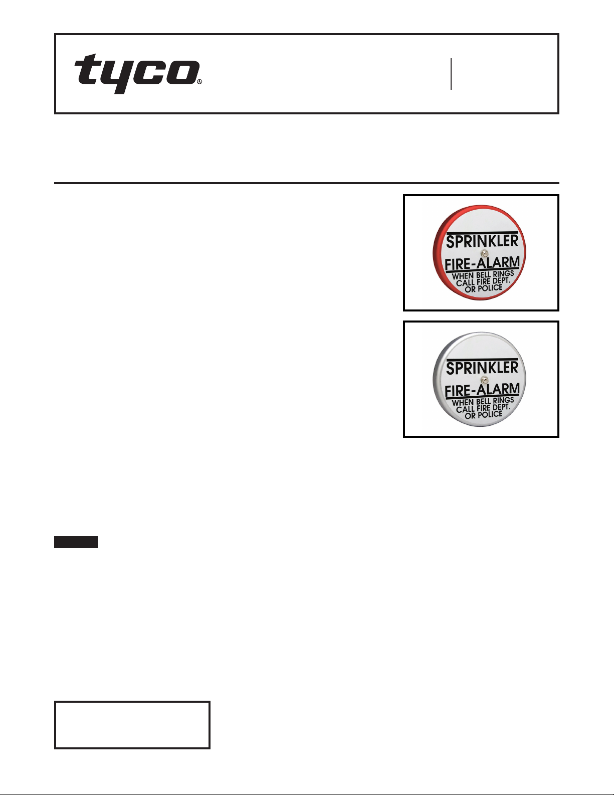
Model WMA-1 Water Motor Alarm
Hydraulically Operated
Mechanical Sprinkler Alarm
Worldwide
Contacts
www.tyco-fire.com
General
Description
The TYCO Model WMA-1 Water Motor
Alarm is a hydraulically operated
outdoor alarm designed for use with
fire protection system waterflow detection valves. It is lightweight yet rugged,
and it can be used in conjunction with
alarm check, dry pipe, deluge, and preaction valves to sound a local alarm.
The Water Motor Alarm is suitable
for mounting to any type of rigid wall
and can accommodate a wall thickness range of 2 in. to 18 in. (50 mm
to 450 mm). It is provided with a listed
and approved TYCO Model WMA-1
Y-Strainer for use in the alarm line.
The Model WMA-1 utilizes a lightweight,
impeller design that can produce a very
high sound pressure level. The Gong,
Gong Mount, and Water Motor Housing
are fabricated from corrosion-resistant
aluminum alloys. The polymer drive
bearings do not require lubrication, and
the Gong is closely fitted to the Gong
Mount to eliminate the need for a separa te cover.
The Model WMA-1 Water Motor Alarm
is a re-designation for the Central
Model F-2, Gem Model F630, and Star
Model S450.
NOTICE
The TYCO Model WMA-1 Water Motor
Alarm described herein must be
installed and maintained in compliance
with this document, as well as with the
applicable standards of the NATIONAL
FIRE PROTECTION ASSOCIATION
(NFPA), in addition to the standards
of any authorities having jurisdiction.
Failure to do so may impair the performance of this device.
IMPORTANT
Refer to Technical Data Sheet
TFP2300 for warnings pertaining to
regulatory and health information.
The owner is responsible for maintaining their fire protection system
and devices in proper operating condition. Contact the installing contractor or product manufacturer with any
questions.
Technical
Data
Approvals
UL and ULC Listed
FM, LPCB and VdS Approved
Gong Finish
Red or Aluminum
Working Water Pressure Range
7 to 300 psi (0,5 to 20,7 bar)
Nozzle K-factor
0.7 gpm/psi½ (10,1 Lp m / b ar½)
Y-Strainer
3/4 in., cast iron, 20 mesh screen
Trim Components
Galvanized steel nipples and cast iron
ttings
Design
Data
The TYCO Model WMA-1 Water Motor
Alarm must be used in accordance with
the following design criteria:
Item 1. The Y-Strainer is to be located
at the alarm outlet of the waterflow
detection valve trim.
Item 2. The Water Motor Alarm
must only be mounted to a rigid
wall surface that will not permit the
Striker /Gong Mount to loosen and fall
out of alignment.
Item 3. In order to obtain the highest
possible sound level, the Water Motor
Alarm should be located as close as
possible to the waterflow detecting
valve. For guidance, refer to NFPA 13.
Item 4. The alarm line piping from the
alarm outlet of the waterflow detection
valve trim to the Water Motor Alarm
must be 3/4 in. (DN20) in size throughout and it must be galvanized steel,
brass, or other suitable corrosion-resistant material.
Item 5. The alarm line piping must be
positioned such that it can be drained
back to the waterflow detection valve
trim.
Item 6. The Clean-Out Sump Plug is to
be located vertically below the Inlet to
the Water Motor.
Item 7. Piping from the Water Motor
Drain must be a minimum of 1 in.
(DN25) in size throughout and directed
to an open drain in order to ensure
proper drainage for obtaining the
maximum sound pressure level.
Note: The Water Motor Alarm Drain
may be connected to the main drain
of a waterflow detection valve if a nonspring loaded swing-type check valve
is installed in a horizontal portion of the
water motor alarm drain piping (before
its connection to the main drain).
Item 8. In order to minimize any wall
staining that can be created by drain
water, it is recommended that the drain
piping from the Water Motor be galvanized steel, brass, or other suitable corrosion-resistant material.
Page 1 of 4 AUGUST 2018 TFP921
Page 2
TFP921
Page 2 of 4
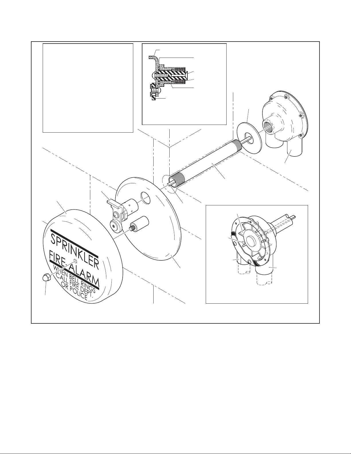
NO. DESCRIPTION REF.
1
Water Motor 92-630-1-012
2
Support Washer
3
Drive Shaft Sleeve
4
Drive Shaft
5
Gong Mount
6
7
8
(a)
(a)
NR: Not Replaceable
. . . . . . . . . . .
Gong
. . . . . . . . . . . .
Cap Nut
Red Gong Repair
Kit includes items:
Aluminum Gong Repair
Kit includes items:
6, 7 (alum.), and 8
7
. . . . . . . . .
. . . . . .
. . .
. . . . . . .
. . . . . .
. . .
QTY.
.
. .
1
1
1
1
1
1
1
1
1
1
6
NR
NR
NR
NR
See (a)Striker
See (a)
See (a)
92-630-1-0256, 7 (red), and 8
92-630-2-025
STRIKER ARM
COUPLING
SPACER
COUPLING
3/4" NPS
STRIKER
SHAFT
STRIKER
RING
CROSS-SECTION VIEW
OF STRIKER (ITEM 6)
BEARING
4
2
1
3
IMPELLER
8
Item 9. Drain water must be directed to
prevent accidental damage to property
or danger to persons when the alarm is
operating or thereafter.
Item 10. The alarm line drain, at the
waterflow detection valve, must be
maintained at a minimum temperature
of 40°F (4°C).
Item 11. A single Water Motor Alarm
may be connected to the alarm lines
from a maximum of three separate fire
protection systems. However, when
two or three alarm lines are interconnected, each alarm line must be provided with the following:
• 3/4 in. Model WM-1 Y-Strainer
(P/N 52-271-1001)
NOZZLE
INLET
5
FIGURE 1
MODEL WMA-1 WATER MOTOR ALARM
AS S E M B LY
•
3/4 in. Check Valve with 3/32 in.
orice (P/N 52-403-1-005)
Strainers must be located at the alarm
outlet in the trim of each of the waterflow detection valves. Check valves
must be located between each strainer
and the interconnection with the alarm
line from another system.
Operation
Upon operation of the alarm check,
dry pipe, deluge, or preaction valve to
which the TYCO Model WMA-1 Water
Motor Alarm is connected, water will
flow to the Water Motor and through
the Inlet Nozzle. As water flows through
DRAIN
INTERNAL VIEW OF
WATER MOTOR (ITEM 1)
the Inlet Nozzle, a high velocity jet is
formed that impinges on the Impeller,
causing the Impeller and the Striker
to rotate. With each rotation, the free
swinging Striker Ring hits the Gong and
sounds the alarm. The spent water is
then drained through the 1 in. outlet.
The alarm will sound as long as water
is flowing into the system and flowing
to the Water Motor Alarm. Water in the
alarm line will automatically drain back
through the orifice, which is also provided in the trim of the waterflow detection valve.
The Water Motor Alarm does not have
to be reset after an operation. However,
if the alarm was silenced during oper-
Page 3

(34,2 mm)
8-1/2" DIA.
2"
Y-STRAINER
2-9/16" T/O
(65,0 mm)
1-3/8"
7/8"
(22,2 mm)
WATER
MOTOR
2-1/2" T/O
(63,5 mm)
2-3/4"
(69,9 mm)
SLEEVE END
3/4" NPT
THREADED
BY INSTALLER
TFP921
Page 3 of 4
(50,8 mm)
3/4" NPS
2-7/16"
(61,9 mm)
(215,9 mm)
3/4" NPT
INLET
3/4" (DN20) NPS
GALVANIZED
STEEL OR
BRASS PIPE
1
3/4"
STRAINER
CLEAN-OUT
CAP
NOTES:
All installation dimensions are shown at nominal value.
1.
2. All dimensions are in inches and (mm).
Items shown in dotted lines are not included with the WMA-1.3.
Consult local Authority Having Jurisdiction for mechanical
4.
alarm isolating control valve requirements.
5. All included trim components are galvanized.
OPTIONAL ELECTRICALLY
SUPERVISED N.O.
ALARM CONTROL VALVE
1" NPT
DRAIN
1" (DN25) NPS
GALVANIZED
4
1
3
2
LOCATION FOR
(SEE NOTE 4)
STEEL OR
BRASS PIPE
MODEL WMA-1 WATER MOTOR ALARM
1-13/16"
(46,0 mm)
DRAIN CL
A
2-1/16"
(52,4 mm)
INLET CL
CLEAN-OUT
SUMP PLUG
STANDARD INLET TRIM
DESCRIPTION
NO.
3/4" x 3" Nipple
1
3/4" 90° Elbow
2
3/4" x 1/4" x 3/4" Tee
3
with 1/4" Plug
3/4" Union
4
FIGURE 2
TYPICAL INSTALLATION
. . . . .
. . . . . .
. . . . . . .
. . . . . . . . .
B
C
D
RIGID WALL
STRUCTURE
16" (457,2 mm)
MAXIMUM
2" (50,8 mm)
MINIMUM
OPTIONAL DRAIN TRIM
QTY.
NO.
DESCRIPTION
A
2
1 . . . . . . .
1
1
1" 90° Elbow
B
1" 45° Elbow
C
Wall Plate
D
1" x 1'-6" Pipe,
. . . . . . .
. . . . . . . . .
. . . . . . . . . . . .T.O.E.
10"
(254,0 mm)
MINIMUM
QTY.
1
1
1
1
ation by closing an alarm control
valve, the alarm control valve must
be reopened after the fire protection
system is restored to service.
Installation
The TYCO Model WMA-1 Water Motor
Alarm must be installed in accordance
with this section.
Step 1. Mark the through-wall locations
for the centerlines of the Sleeve and
Drain Outlet. The Drain Outlet must be
located at least 10 in. (250 mm) below
the Sleeve per Figure 2.
Step 2. Make 1-1/2 in. (38 mm) diameter holes straight through the wall at
both locations.
Step 3. Cut the non-threaded end of
the Sleeve to a length equal to that of
the wall thickness plus 0 in. to 1/8 in.
(0 mm to 3 mm). Thread the cut end to
3/4 in. NPT per ANSI B1.20.1.
Step 4. Install the alarm line piping up
to and including the Union half per Item
4, Figure 2.
Note: Use thread sealant sparingly on
male threads only.
Step 5. Prior to initiating installation
of the Water Motor Alarm, mount the
Drain Trim (less the Wall Plate and 45°
Elbow) as well as the balance of alarm
line piping, including the other Union
half, to the Water Motor.
Step 6. Tighten the NPT threaded end
of the Sleeve into the Body, hand-tight
plus 1/8 turn.
Step 7. Slip the Support Washer over
the Sleeve and place the assembly in
position against the wall.
Step 8. Tighten the 3/4 in. Union.
Install the Wall Plate and tighten the
45° Elbow.
Note: Apply pressure against the
outside edge of the Water Motor Body
and verify that the Body and Support
Washer sit squarely against the wall. If
not, adjust the alarm line and/or drain
piping to suit.
Step 9. From the outside wall, insert
the Drive Shaft through the Sleeve and
fully insert it into the Impeller.
Note: When fully inserted, the Shaft
should protrude beyond the face of
the wall by approximately 20 minus 2 in.
(508,0 minus 50,8 mm) wall thickness.
Mark the Drive Shaft at a point of
approximately 1/8 in. to 1/4 in. (3,2 mm
to 6,4 mm) inside the face of the wall.
Remove the Shaft and cut it where pre-
Page 4

TFP921
Page 4 of 4
viously marked. File off burrs from the
cut end of the Drive Shaft. Re-insert the
Drive Shaft through the Sleeve and fully
insert it into the Impeller.
Step 10. Hold the Gong Mount in
position against the wall, engage the
Coupling with the Drive Shaft, and
then carefully thread the Striker Shaft
Bearing onto the Sleeve. Securely
tighten the Striker Shaft Bearing using
a pair of tongue-and-groove pliers on
the 1-1/2 in. (38 mm) hex end.
Step 11. Spin the Striker by hand and
verify that it spins freely, without any
sign of binding. If it does not, make the
necessary adjustments.
Step 12. Install the Gong and securely
tighten the Cap Nut. The identification sign lettering must be orientated
horizontally.
Step 13. Test the Water Motor Alarm by
opening the alarm test valve in the trim
of the waterflow detection valve. The
alarm must be clear and steady. If it is
not, make the necessary adjustments.
NOTICE
Testing of the Water Motor Alarm may
result in operation of other associated
alarms. Consequently, notification
must be given to the owner and the fire
department, central control station, or
other signal station to which the alarms
are connected.
Care and
Maintenance
The TYCO Model WMA-1 Water Motor
Alarm must be maintained and serviced in accordance with this section.
Before closing a fire protection system
main control valve for maintenance
work on the fire protection system
that it controls, obtain permission to
shut down the affected fire protection
system from the proper authorities
and notify all personnel who may be
affected by this decision.
Testing of the Water Motor Alarm may
result in operation of other associated
alarms. Consequently, notification
must be given to the owner and the fire
department, central control station, or
other signal station to which the alarms
are connected.
If the alarm was silenced during operation, the alarm control valve must be
reopened immediately after the fire protection system is restored to service.
The owner is responsible for the inspection, testing, and maintenance of their
fire protection system and devices in
compliance with this document, as well
as with the applicable standards of the
NATIONAL FIRE PROTECTION ASSOCIATION (e.g., NFPA 25), in addition to
the standards of any other authorities
having jurisdiction. Contact the installing contractor or product manufacturer
regarding any questions.
Automatic sprinkler systems are recommended to be inspected, tested,
and maintained by a qualified Inspection Service in accordance with local
requirements and/or national codes.
The following procedures and inspections should be performed as indicated,
in addition to any specific requirements
of the NFPA, and any impairment must
be immediately corrected:
Step 1. The Model WMA-1 Water Motor
Alarm does not require any regularly
scheduled maintenance. Rotating parts
do not require lubrication. It is recommended, however, that fire alarms be
periodically operated (inspected) to
verify that they generate a clear and
steady sound. Correct any impairment
immediately.
Step 2. The inspection should be made
quarterly or more frequently, as may
be necessary for locations subject to
vandalism.
The Y-Strainer and Sump are to be
cleaned out after each operation of the
Water Motor Alarm and after the alarm
line piping has been drained.
NOTICE
With reference to Figure 2, in the event
of a WMA-1 malfunction, inspect and
clean the Y-Strainer of obstruction prior
to removing the Water Motor.
Make no attempt to disassemble,
repair, or internally clean the Water
Motor. The Water Motor is not a field
serviceable part and must be replaced
if malfunction is determined.
Limited
Warranty
For warranty terms and conditions, visit
www.tyco-fire.com.
Ordering
Procedure
Orders for the WMA-1 Water Motor
Alarm Assembly, Optional Drain Trim,
and replacement parts must include
the description and Part Number (P/N).
The complete Model WMA-1 Alarm
Assembly includes the Model WMA-1
Water Motor Alarm, Model WM-1
Strainer, and Standard Inlet Trim.
WMA-1 Water Motor Alarm
Assembly
Specify: Model WMA-1 Water Motor
Alarm, (specify) Finish, P/N (specify):
Red Finish Gong .........P/N 5 2- 6 3 0 -1- 0 01P
Aluminum Finish Gong. . . . . P/ N 52-630 -2-001P
Optional Drain Trim
Specify: Optional Drain Trim for
Model WMA-1 Water Motor Alarm,
P/N 52-630-2-002
Separately Ordered Parts for
Multiple Systems
Specify: Model WM-1 Y-Strainer,
P/ N 52-271-1-001
Note: One Y-Strainer is required for
two systems; two Y-Strainers are
required for three systems.
Specify: 3/4 in. Check Valve with 3/32
in. Orifice, P/N 52-403-1-005
Note: Two Check Valves are required
for two systems; three Check Valves
are required for three systems.
Replacement Parts for
Water Motor Alarm
Specify: (description) for use with
Model WMA-1 Water Motor Alarm,
P/N (see Figure 1)
1400 Pennbr ook Parkway, Lansdale , PA 19446 | Telephone +1-215-3 62- 0700
© 2018 John son Control s. All right s reserved. A ll specifica tions and ot her informa tion shown wer e current as o f document rev ision date an d are subject t o change wit hout notice.
NATIONAL FIRE P ROTECTION ASSOCIATIO N and NFPA are register ed trademarks of N ational Fire Protec tion Associati on;
 Loading...