

Page 1
Worldwide
Contacts
www.tyco-fire.com
Series TY-L — 5.6 and 8.0 K-factor
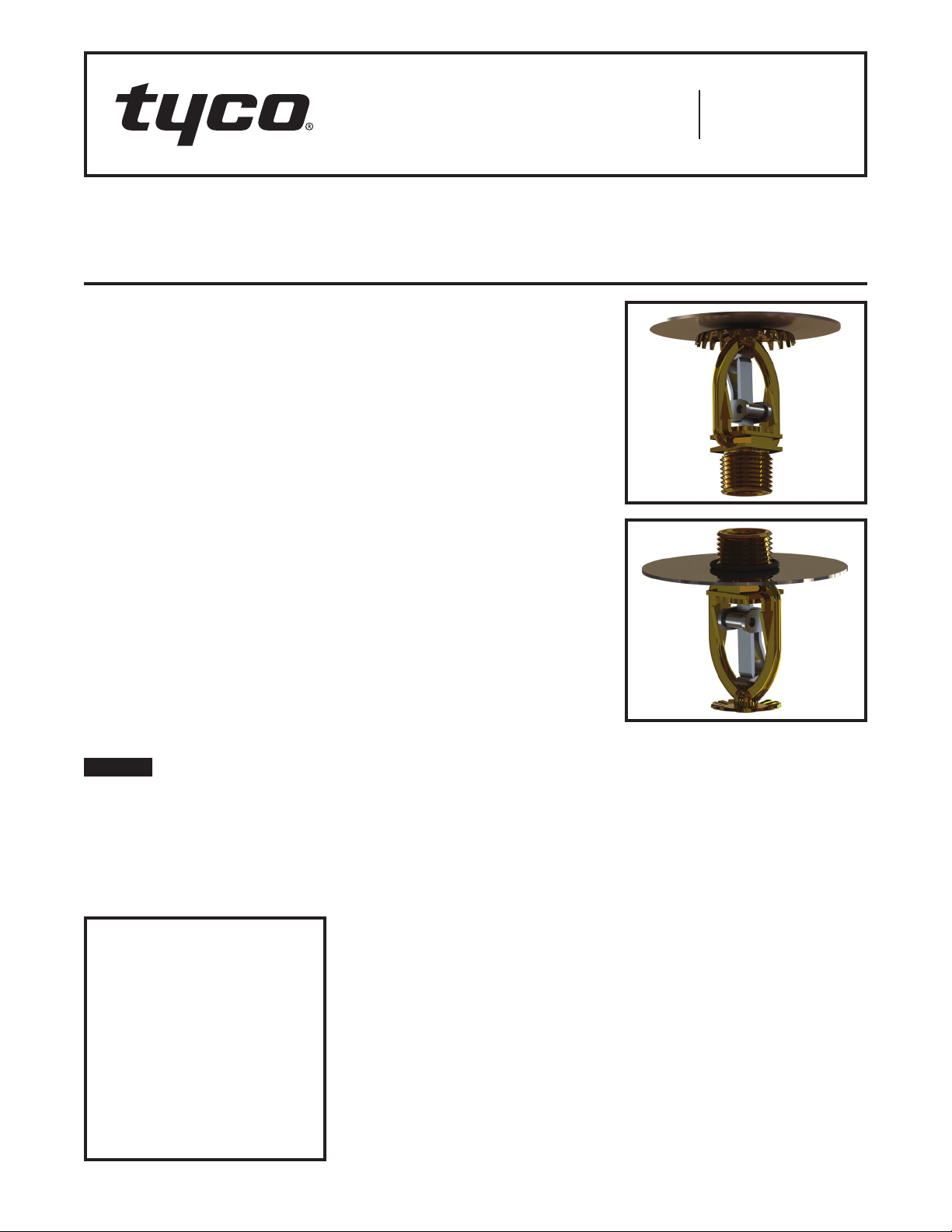
Upright and Pendent Intermediate Level Sprinklers
Standard Response
General
Description
The Series TY-L, 5.6 and 8.0 K-factor Upright and Pendent Intermediate Level Sprinklers described in this
data sheet are automatic sprinklers
of the “standard response” solder
type. They are “standard spray” sprinklers intended for use in fire sprinkler
systems designed in accordance with
the standard installation rules recognized by the applicable Listing or
Approval agency (e.g., UL Listing is
based on NFPA requirements). Both
the Pen dent and Upright Sprinklers
produce a hemispherical water distribution pattern below the deflector.
Intermediate Level Sprinklers are primarily designed for use in rack storage
sprinkler systems where their thermally
sensitive elements must be shielded
from the water spray of higher elevation sprinklers that could operate
earlier during a fire. Intermediate Level
Sprinklers are also used in other applications such as beneath open gridded
catwalks.
NOTICE
The Series TY-L Sprinklers described
herein must be installed and maintained in compliance with this document, as well as with the applicable
standards of the National Fire Protection Association, in addition to the standards of any other authorities hav ing
jurisdiction. Failure to do so may impair
the performance of these devices.
IMPORTANT
Refer to Technical Data Sheet
TFP2300 for warnings pertaining to
regulatory and health information.
Always refer to Technical Data
Sheet TFP700 for the “INSTALLER
WARNING” that provides cautions
with respect to handling and installation of sprinkler systems and components. Improper handling and
installation can permanently damage
a sprinkler system or its components and cause the sprinkler to fail
to operate in a fire situation or cause
it to operate prematurely.
The owner is responsible for maintaining their fire protection system
and devices in proper operating condition. Contact the installing contractor or product manufacturer with any
questions.
Sprinkler
Identification
Number (SIN)
TY3113 – Upright 5.6K, 1/2”NPT
TY3211 – Pendent 5.6K, 1/2”NPT
TY4113 – Upright 8.0K, 3/4”NPT
TY4211 – Pendent 8.0K, 3 /4”NPT
TY3113 is a redesignation for S1809
and G3253
TY3211 is a redesignation for S1801
and G3112
TY4113 is a redesignation for S1822
and G3153
TY4211 is a redesignation for S1811
and G3102
Technical
Data
Approvals
UL and C-UL Listed
FM Approved
(Refer to Table A for complete approval
information including corrosion resistant
status.)
Maximum Working Pressure
175 psi (12,1 bar)
Discharge Coefficient
K = 5.6 gpm/psi½ (80,6 lpm/bar½)
K = 8.0 gpm/psi½ (11 5, 2 l p m /ba r½)
Temperature Ratings
Refer to Table A
Finishes
Natural Brass
Physical Characteristics
Frame . . . . . . . . . . . . . . . . . . . . . . . . . . . . . Brass
Sealing Button . . . . . . . . . . . Bronze w/ TEFLON
Ejection Spring . . . . . . . . . . . . . . Stainless Steel
Strut. . . . . . . . . . . . . . . . . . . . . . . . . . . . . MONEL
Hook ..................... Bronze/MONEL
Deflector . . . . . . . . . . . . . . . . . . . . . . . . . .Bronze
Shield . . . . . . . . . . . . . . . . . . . . . . . . . . . . .Brass
Fusible Element . . . . . . . . . . . . .Solder, Copper,
Stainless Steel
Page 1 of 4 AUGUST 2018 TFP350
Page 2
TFP350
(68,3 mm)
(FIELD ASSEMBLED - SEE INSTALLATION SECTION)(FACTORY ASSEMBLED)
3" (76,2 mm) DIA,
(66,7 mm)
(FACTORY ASSEMBLED)
3" (76,2 mm) DIA,
(69,9 mm)
(FIELD ASSEMBLED - SEE INSTALLATION SECTION)
(68,3 mm)
Page 2 of 4
1/2" NPT
2-11/16"
7/16"
(11,1 mm)
NOMINAL
MAKE-IN
UPRIGHT PENDENT
FACTORY
ASSEMBLED
UPRIGHT
SHIELD
WRENCH
FLANGES
WRENCH
AREA
MODEL S5
PENDENT
SHIELD
WITH
O-RINGS
7/16"
(11,1 mm)
NOMINAL
MAKE-IN
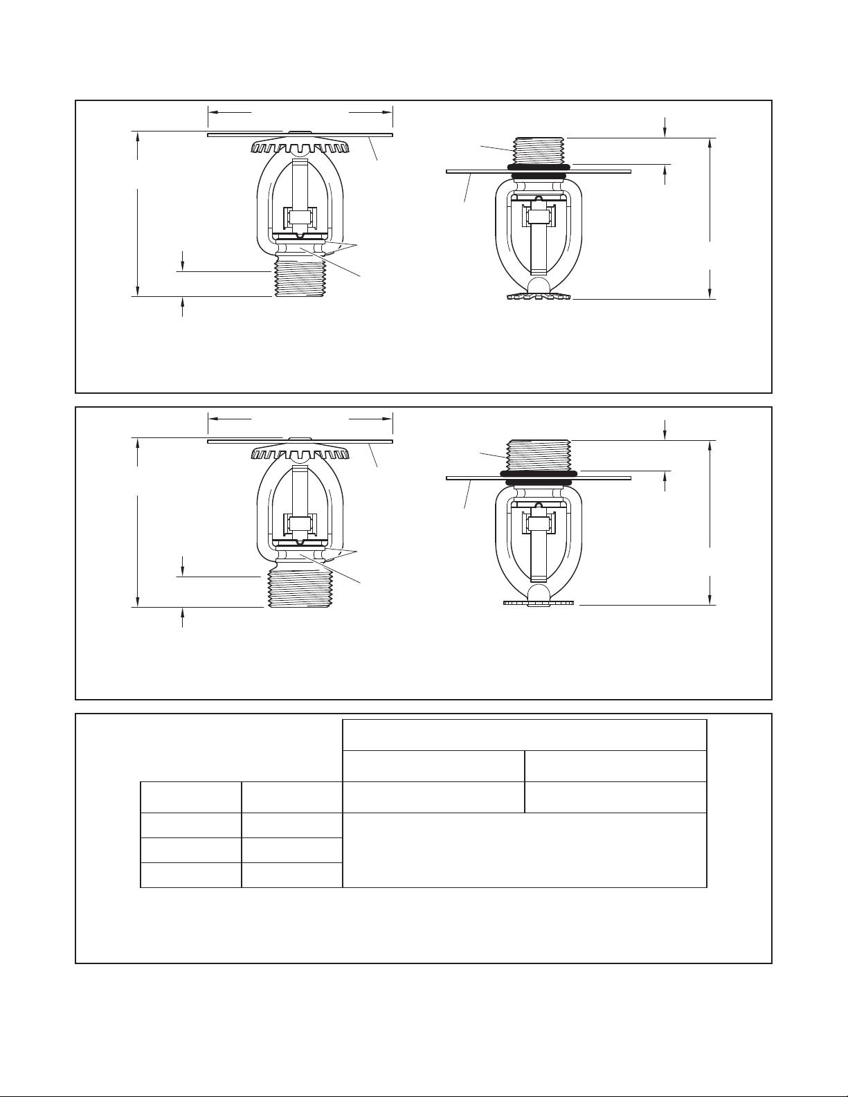
FIGURE 1
STANDARD RESPONSE SERIES TY-L UPRIGHT ( TY3113) AND PENDENT (TY3211) SPRINKLERS
INTERMEDIATE LEVEL SPRINKLERS, 5.6 K-FACTOR, 1/2 INCH NPT
3/4" NPT
2-3/4"
1/2"
(12,7 mm)
NOMINAL
MAKE-IN
FACTORY
ASSEMBLED
UPRIGHT
SHIELD
WRENCH
FLANGES
MODEL S5
PENDENT
SHIELD
WITH
O-RINGS
1/2"
(12,7 mm)
NOMINAL
MAKE-IN
2-5/8"
2-11/16"
WRENCH
AREA
UPRIGHT PENDENT
FIGURE 2
STANDARD RESPONSE SERIES TY-L UPRIGHT ( TY4113) AND PENDENT (TY4211) SPRINKLERS
INTERMEDIATE LEVEL SPRINKLERS, 8.0 K-FACTOR, 3/4 INCH NPT
SPRINKLER FINISH
K = 5.6 UPRIGHT TY3113
K = 5.6 PENDENT TY3211
TEM P.
RATI NG
16 5°F (74° C ) UNPAINTED
280° F (138°C) BLUE
NOTES
1. Listed by Under write rs Lab orator y, Inc. (UL).
2. Listed by Unde rwriters L abora tory, Inc. for use in Ca nada (C-UL)
3. A pprove d by Factor y Mutual Research Corporation.
FRAME COLOR
CODE
NATURAL BRASS NATURAL BRASS
K = 8.0 UPRIGHT TY4113
K = 8.0 PENDENT TY4211
1, 2, 3212°F (100°C) WHITE
TABL E A
LABORATORY LISTINGS AND APPROVALS
Page 3

TFP350
WRENCH
Page 3 of 4
Operation
A copper tube sealed by two stainless
steel balls holds a fusible alloy. When
the rated temperature is reached, the
alloy melts, the balls are forced toward
each other releasing the tension mechanism, allowing the sprinkler to operate.
Design
Criteria
The Series TY-L Pendent and Upright
Intermediate Level Sprinklers are
intended for fire protection systems
designed in accordance with the standard installation rules recognized by
the applicable Listing or Approval
agency (e.g., UL Listing is based on
the requirements of NFPA 13, and FM
Approval is based on the requirements
of FM Global’s Loss Prevention Data
Sheets).
Installation
The Series TY-L Sprinklers must
be installed in accordance with this
section.
NOTE: A leak-tight 1/2 in. NPT sprinkler joint should be obtained by applying a minimum-to-maximum torque of
7 to 14 lb-ft (9,5 to 19,0 N·m). A leak
tight 3/4 in. NPT sprinkler joint should
be obtained by applying a minimumto-maximum torque of 10 to 20 lb-ft
(13,4 to 26,8 N·m). Higher levels of
torque may distort the sprinkler inlet
and cause leakage or impairment of
the sprinkler.
Upright Sprinklers
The Series TY-L Intermediate Level
Upright Sprinklers must be installed
in accordance with the following
instructions.
Step 1. With pipe thread sealant
applied to the pipe threads, hand
tighten the sprinkler into the sprinkler
fitting.
Step 2. Tighten the sprinkler into the
sprinkler fitting using only the W-Type
9 Sprinkler Wrench (Ref. Figure 3). With
reference to Figure 1 or 2, the W-Type
9 Sprinkler Wrench is to be applied to
the wrenching area.
Pendent Sprinklers
The Series TY-L Intermediate Level
Pendent Sprinklers must be installed
in accordance with the following
in structions.
Step 1. Roll one of the two required
O-Rings over the sprinkler threads until
it seats against the sprinkler wrenching
area flange as shown in Figure 1 or 2,
as applicable.
Step 2. Install the Shield over the sprinkler threads, and then roll the second
O-Ring over the sprinkler threads until
it is seated firmly against the Shield.
Step 3. With pipe thread sealant
ap plied, hand tighten the sprinkler into
the sprinkler fitting.
Step 4. Tighten the sprinkler into the
sprinkler fitting using only the W-Type
9 Sprinkler Wrench (Ref. Figure 3). The
wrench is to be applied to the sprinkler
wrenching area shown in Figure 1 or 2,
as applicable.
When installed correctly, the O-Rings
will be slightly compressed and the
Shield will be held firmly in place.
RECESS
FIGURE 3
W-TYPE 9 SPRINKLER
WRENCH
Care and
Maintenance
The Series TY-L Sprinklers must be
maintained and serviced in accordance
with this section.
Before closing a fire protection system
main control valve for maintenance
work on the fire protection system that
it controls, permission to shut down the
affected fire protection system must be
obtained from the proper authorities
and all personnel who may be affected
by this action must be notified.
Sprinklers that are found to be leaking
or exhibiting visible signs of corrosion
must be replaced.
Automatic sprinklers must never be
painted, plated, coated or otherwise
altered after leaving the factory. Modified or over-heated sprinklers must be
replaced.
Care must be exercised to avoid
damage to the sprinklers before,
during, and after installation. Sprinklers damaged by dropping, striking,
wrench twist/slippage, or the like, must
be replaced.
The owner is responsible for the
inspection, testing, and maintenance of
their fire protection system and devices
in compliance with this document, as
well as with the applicable standards
of the National Fire Protection Association (e.g., NFPA 25), in addition to
the standards of any other authorities
having jurisdiction. Contact the installing contractor or product manufacturer
with any questions.
It is recommended that automatic
sprinkler systems be inspected, tested,
and maintained by a qualified Inspection Service in accordance with local
requirements and/or national codes.
Page 4

TFP350
Page 4 of 4
P/N 53 — XXX — X — XXX
SIN
253 5.6K UPRIGHT (1/2 in. NPT) T Y311 3
153 8.0K UPRIGHT (3/4 in. NPT) T Y4113
PART NUMBER SELECTION
SERIES TY-L UPRIGHT INTERMEDIATE LEVEL SPRINKLERS
(UPRIGHT SHIELD INCLUDED WITH SPRINKLER)
P/N 51 — XXX — X — XXX
SIN
112 5.6K PENDENT (1/2 in. NPT) T Y3211
102 8.0K PENDENT (3/4 in. NPT) T Y42 11
PART NUMBER SELECTION
SERIES TY-L PENDENT SPRINKLERS
(MODEL S5 PENDENT SHIELD & O-RING MUST BE SEPARATELY ORDERED)
1 NATURAL BRASS
TABL E B
1 NATURAL BRASS
TABL E C
SPRINKLER
SPRINKLER
TEMPERATURE
RATI NG
165 16 5°F (74° C )
212 212°F (100°C)
280 280° F (138°C)
TEMPERATURE
RATI NG
165 16 5°F (74° C )
212 212°F (100°C)
280 280° F (138°C)
Limited
Warranty
For warranty terms and conditions, visit
www.tyco-fire.com.
Ordering
Procedure
Contact your local distributor for availability. When placing an order, indicate
the full product name and Part Number
(P/N).
Upright Sprinkler Assemblies
with Shield and NPT Thread
Connections
Specify: (Specify Model/SIN), Standard Response, (specify K-factor),
(specify temperature rating), Series
TY-L Upright Intermediate Level Sprinklers with natural brass finish, P/N
(specify from Table B)
Pendent Sprinkler Assemblies with
(Shield Ordered Separately) and
NPT Thread Connections
Specify: (Specify Model/SIN), Standard Response, (specify K-factor),
(specify temperature rating), Series
TY-L Pendent Sprinkler with natural
brass finish, P/N (specify from Table C)
Model S5 Pendent Shield Package
Specify: S5 Pendent Shield Package
(one shield / two O-Rings) for use with
(specify 1/2 in. NPT or 3/4 in. NPT)
Series TY-L Pendent Sprinklers, P/N
(specify)
1/2 in. NPT ...................56-015-6-802
3/4 in. NPT ...................56-015-6-803
Sprinkler Wrench
Specify: W-Type 9 Sprinkler Wrench,
P/N 56-000-1-849
1400 Pennbr ook Par kway, L ansd ale, PA 19446 | Tele phon e +1-215-36 2-07 00
© 2018 John son Control s. All right s reserved. A ll specifica tions and ot her informa tion shown wer e current as o f document rev ision date an d are subject t o change wit hout notice.
NATIONAL FIRE P ROTECTION ASSOCIATIO N and NFPA are register ed trademarks of N ational Fire Protec tion Associati on;
MONEL is a reg istered tradema rk of Special Met als Corporatio n;
TEFLON is a regi stered tradema rk of DuPont
 Loading...