

Page 1
Worldwide
Contacts
www.tyco-fire.com
Worldwide
Contacts
www.tyco-fire.com
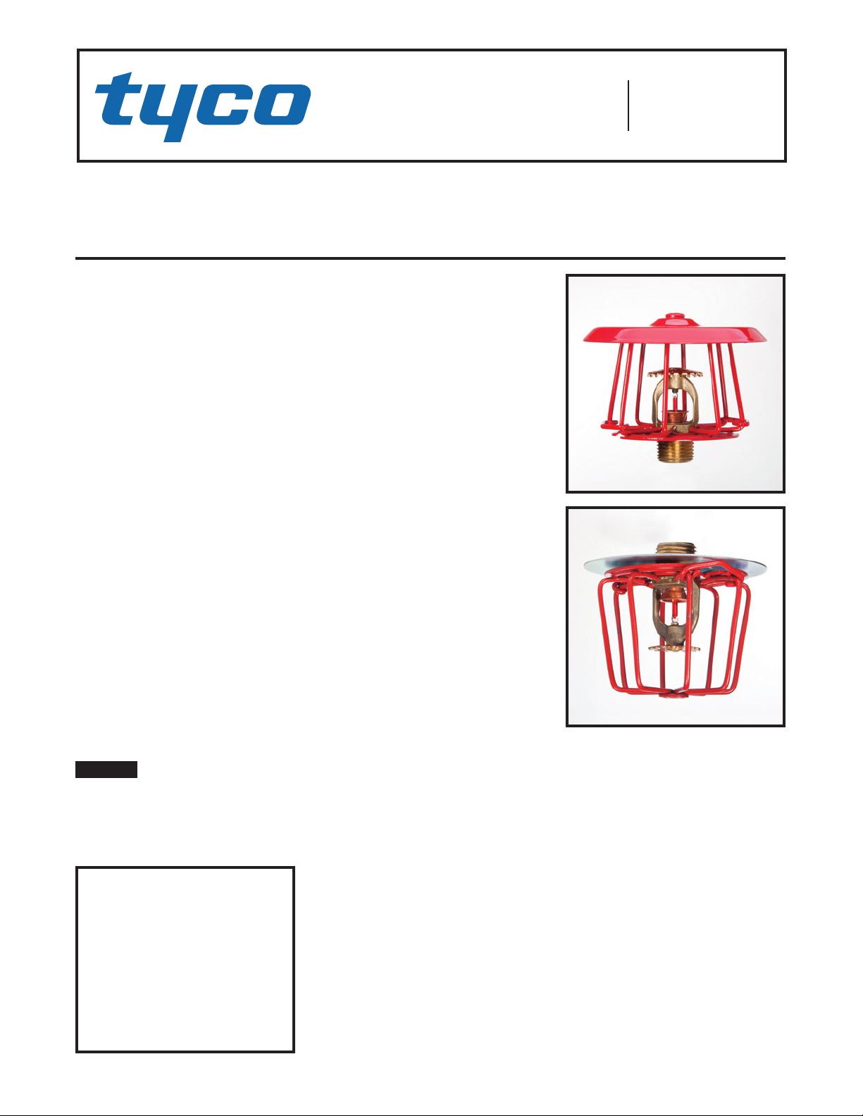
Series TY-FRB — 5.6 K-factor
Upright and Pendent Intermediate Level Sprinklers
Quick Response
General
Description
The Series TY-FRB, 5.6 K-factor Upright and Pendent Intermediate Level
Sprinklers described in this data sheet
are automatic sprinklers of the “quick
response” 3 mm frangible bulb type.
They are “standard spray” sprinklers
intended for use in fire sprinkler systems designed in accordance with the
standard installation rules recognized
by the applicable Listing or Approval
agency (e.g., UL Listing is based on
NFPA requirements). Both the Upright and Pendent Sprinklers produce
a hemispherical water distribution pattern below the deflector.
Intermediate Level Sprinklers are primarily designed for use in rack storage sprinkler systems where their
thermally sensitive elements must be
shielded from the water spray of higher elevation sprinklers that could operate earlier during a fire. Intermediate
Level Sprinklers are also used in other applications such as beneath open
gridded catwalks.
For additional Series TY-FRB Sprinkler information, see Technical Data
Sheet TFP172. For additional Guard
and Shield information, see Technical
Data Sheet TFP780.
NOTICE
The Series TY-FRB Sprinklers described herein must be installed and
maintained in compliance with this
document, as well as with the applicable standards of the National Fire
IMPO R TA N T
Always refer to Technical Data
Sheet TFP700 for the “INSTALLER
WARNING” that provides cautions
with respect to handling and installation of sprinkler systems and components. Improper handling and installation can permanently damage
a sprinkler system or its components and cause the sprinkler to fail
to operate in a fire situation or cause
it to operate prematurely.
Protection Association, in addition to
the standards of any other authorities
having jurisdiction. Failure to do so
may impair the performance of these
devices.
The owner is responsible for maintaining their fire protection system and
devices in proper operating condition. The installing contractor or sprinkler manufacturer should be contacted with any questions.
Sprinkler
Identification
Numbers
TY313 . . . . . . . . . . Upright 5.6K, 1/2” NPT
TY323 ..........Pendent 5.6K, 1/2” NPT
Technical
Data
Approvals
UL and C-UL Listed
FM Approved
(Refer to Table A for complete approval information.)
Maximum Working Pressure
175 psi (12,1 bar)
250 psi (17,2 bar)*
* The Maximum Working Pressure of 250 psi (17,2
bar) only applies to the listing by Underwriters
Laboratory.
Discharge Coefficient
1/2
K=5.6 GPM/psi
Temperature Ratings
Refer to Table A
Finishes
TY-FRB Sprinkler . . . . . . . . . . . . . . . Brass
G1/S1 Guard with Shield .....Red or Zinc
G1 Guard .................Red or Zinc
S2 Shield ...................... Zinc
(80,6 LPM/bar
1/2
)
Physical Characteristics
Frame ....................... Bronze
Button................. Brass/Copper
Sealing Assembly....... Stainless Steel
w/TEFLON
Bulb ......................... Glass
Compression Screw. . . . . . . . . . . . Bronze
Deflector.....................Copper
G1 and G1/S1 Guard ...Painted or Plated
Steel
S2 Shield ................ Plated Steel
Operation
The glass bulb contains a fluid which
expands when exposed to heat. When
the rated temperature is reached, the
fluid expands sufficiently to shatter
the glass bulb, allowing the sprinkler
to activate and water to flow.
Page 1 of 6 MA R CH 2013 TFP357
Page 2
TFP357
*
(73,0 mm)
NOMINAL MAKE-IN
3-1/2" DIA.
ordered seperately.
Pipe thread
*
(73,0 mm)
NOMINAL MAKE-IN
ordered seperately.
Pipe thread
FACTORY ASSEMBLED
4" DIA.
*
3-1/2" DIA.
ordered seperately.
Pipe thread
(50,8 mm)
Page 2 of 6
SHIELD
3"
(76,2 mm)
2-3/8"
(60,3 mm)
7/16" (11,1 mm)
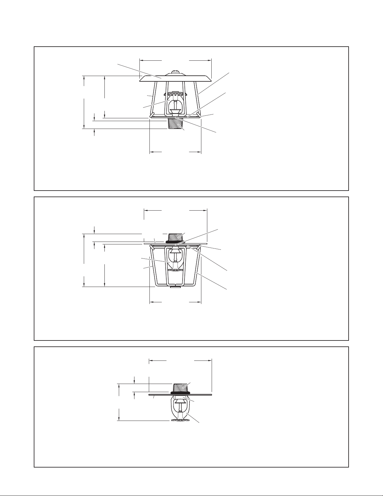
SERIES TY-FRB UPRIGHT (TY313) INTERMEDIATE LEVEL SPRINKLER
7/16" (11,1 mm)
2-3/8"
(60,3 mm)
3"
(76,2 mm)
MODEL G1/S1
GUARD WITH
SHIELD
TY-FRB
TY-FRB
MODEL G1
GUARD
**
MODEL S2
SHIELD WITH
**
(101,6 mm)
2-7/8"
1/2"
NPT
*
GUARD
BAR
GUARD
BASE PLATE
GUARD CLIP
ENGAGED
AGAINST GUARD
BASE PLATES
SPRINKLER
THREAD RELIEF
ENGAGED BY GUARD
BASE PLATES
FIGURE 1
WITH G1/S1 GUARD WITH SHIELD
O-RING
(88,9 mm)
2-7/8"
1/2"
NPT
*
SPRINKLER
THREAD RELIEF
ENGAGED BY GUARD
BASE PLATES
GUARD CLIP
ENGAGED
AGAINST GUARD
BASE PLATES
GUARD
BASE PLATE
GUARD
BAR
connections per
ISO 7-1 can be
provided on
special request.
Temperature
**
rating is indicated
on Deector.
TY-FRB Sprinkler
and G1/S1 Guard
with Shield are
connections per
ISO 7-1 can be
provided on
special request.
Temperature
**
rating is indicated
on Deector.
TY-FRB Sprinkler,
G1 Guard, and
S2 Shield with
O-Ring are
SERIES TY-FRB PENDENT (TY323 ) INTERMEDIATE LEVEL SPRINKLER
FIGURE 2
WITH S2 SHIELD AND G1 GUARD
7/16" (11,1 mm)
NOMINAL MAKE-IN
2"
SHIELD WITH
MODEL S2
O-RING
(88,9 mm)
1/2"
NPT
*
SPRINKLER
WRENCH
FLATS
TY-FRB
**
**
connections per
ISO 7-1 can be
provided on
special request.
Temperature
rating is indicated
on Deector.
TY-FRB Sprinkler
and S2 Shield
with O-Ring are
FIGURE 3
SERIES TY-FRB PENDENT (TY323 ) INTERMEDIATE LEVEL SPRINKLER
WITH S2 SHIELD
Page 3

TFP357
WITH SPRINKLER PROPERLY INSTALLED,
CAREFULLY SPREAD BASE PLATES APART AND FIT
PLATES UNTIL SNUG
PLATES
INSTALLATION
CLIP FULLY
TOWARD BASE PLATES UNTIL FULLY ENGAGED
Page 3 of 6
K TYPE TE M P.
5.6
1/2”
NPT
NOTES :
1. Listed by Underwriters Laboratories, Inc. (UL).
2. Listed by Underwriters Laboratories, Inc. for use in Canada (C-UL).
3. Approved by Factory Mutual Research Corporation (FM).
GUARD ONTO SPRINKLER ENGAGING SPRINKLER
THREAD RELIEF BY BASE PLATES
BASE
PLATES
CLIP
ADJACENT
BAR
MODEL
G1 GUARD
SWIVEL CLIPS OVER ADJACENT
BARS AND SLIDE TOWARD BASE
SERIES TY-FRB
PENDENT
SPRINKLER
BULB
LIQUID
135° F (57 °C ) Orange
UPRIGHT
(T Y313 )
with Guard/
Shield
(G1/S1)
PENDENT
(TY323)
with Guard/
Shield
(G1/S2) or
Shield only
(S2)
155° F (68° C) Red
175°F ( 7 9 °C) Yel l ow
200°F (93°C) Green
28 6°F (141°C ) Blue
135° F (57 °C ) Orange
155° F (68° C) Red
175°F ( 7 9 °C) Yel l ow
200°F (93°C) Green
28 6°F (141°C ) Blue
TABL E A
LABORATORY LISTINGS AND APPROVALS
MODEL
G1/S1 GUARD
WITH SHIELD
SERIES TY-FRB
MODEL
S2 SHIELD
FIRST
CLIP FULLY
ENGAGED
BAR
SLOT
INSTALLATION TOOL
(SHIPPED WITH
GUARDS)
UPRIGHT
SPRINKLER
FIRST
CLIP FULLY
ENGAGED
WITH INSTALLATION TOOL APPLIED OVER
ADJACENT BARS, PRESS SECOND CLIP
SPRINKLER FINISH
NATURAL BRASS
1, 2, 3
INSTALLATION
TOOL
CLIP
SECOND
ENGAGED
BASE
TOOL
CLIP
A PLIER
MAY BE
USED
INSTALLATION PROCEDURES FOR MODEL G1 GUARD AND S2 SHIELD (PENDENT SPRINKLER )
FIGURE 4
AND MODEL G1/S1 GUARD WITH SHIELD (UPRIGHT SPRINKLER)
Page 4

TFP357
WRENCH RECESS
Page 4 of 6
Design
Criteria
The Series TY-FRB, 5.6 K-factor Upright and Pendent Intermediate Level
Sprinklers are intended for fire protection systems designed in accordance with the standard installation
rules recognized by the applicable
Listing or Approval agency (e.g., UL
Listing is based on the requirements
of NFPA 13, and FM Approval is based
on the requirements of FM’s Loss Prevention Data Sheets).
Installation
The Series TY-FRB, 5.6 K-factor Upright and Pendent Intermediate Level
Sprinklers must be installed in accordance with this section:
General Instruction
Do not install any bulb type sprinkler if the bulb is cracked or there is
a loss of liquid from the bulb. With the
sprinkler held horizontally, a small air
bubble should be present. The diameter of the air bubble is approximately
1/16 inch (1,6 mm) for the 135°F (57°C)
to 3/32 inch (2,4 mm) for the 286°F
(141°C) temperature ratings.
A leak tight 1/2 inch NPT sprinkler
joint should be obtained with a torque
of 7 to 14 ft.-lbs. (9,5 to 19,0 Nm).
Higher levels of torque may distort the
sprinkler inlet and cause leakage or
impairment of the sprinkler.
Upright Sprinklers
The Series TY-FRB Intermediate Level Upright Sprinklers must be installed
in accordance with the following
instructions.
Step 1. With pipe thread sealant applied to the pipe threads, hand tighten
the sprinkler into the sprinkler fitting.
Step 2. Tighten the sprinkler into the
sprinkler fitting using only the W-Type
6 Sprinkler Wrench (Ref. Figure 5).
With reference to Figure 1, the W-Type
6 Sprinkler Wrench is to be applied to
the wrench flats.
Step 3. Mount the Model G1/S1
Guard with Shield on the sprinkler.
With the Clips loose, spread the two
halves of the Sprinkler Guard enough
to pass by the sprinkler deflector from
the side.
Step 4. Spread the two halves of
the Sprinkler Base Plates enough to
pass over the sprinkler Thread Relief
portion of the sprinkler. (Refer to
Figure 1.)
Step 5. With the Sprinkler Guard positioned on the Thread Relief portion
of the sprinkler, engage the Bars with
Clips from opposing Guard Halves,
then slide the Clips up until they are
seated against the Base Plates, completing the installation as shown in
Figure 1 and 4.
NOTE: To help assist with the sliding
of the Clips, use the Guard Installation
Tool as shown in Figure 4. Additionally, pliers can be used to facilitate the
final seating of the Clips.
NOTICE
The Clips must seat against the Base
Plates to be fully seated in order to
complete the installation. The Model
G1/S1 Guard with Shield may be located in any position relative to the
sprinkler frame arms.
Pendent Sprinklers
The Series TY-FRB Intermediate Level Pendent Sprinklers must be installed in accordance with the following instructions.
Step A. Thread the S2 Shield on to
the sprinkler threads with the stamped
markings toward the deflector and
just to the end of the threads. The final assembly step is easier to accomplish if the Shield is not disengaged by
continuing to turn the Shield past the
threads.
Step B. Roll the O-Ring over the
sprinkler threads until it seats against
the Shield.
Step C. With pipe thread sealant applied to the pipe threads, hand tighten
the sprinkler into the sprinkler fitting.
Step D. Tighten the sprinkler into the
sprinkler fitting using only the W-Type
6 Sprinkler Wrench (Ref. Figure 5).
With reference to Figure 2 or 3, the WType 6 Sprinkler Wrench is to be applied to the wrench flats.
Step E. Rotate the S2 Shield clockwise (looking up) so that it slightly
compresses the O-Ring between the
Shield and sprinkler fitting.
Note: Installation of the S2 Shield only
is completed at this point (Ref. Figure
3). If installing a G1 Guard, proceed to
the next step.
Step F. Mount the Model G1 Guard
on the sprinkler. With the Clips loose,
spread the two halves of the Sprinkler
Guard enough to pass by the sprinkler
deflector from the side.
Step G. Spread the two halves of
the Sprinkler Base Plates enough to
pass over the sprinkler Thread Relief
portion of the sprinkler. (Refer to
Figure 2.)
Step H. With the Sprinkler Guard positioned on the Thread Relief portion
of the sprinkler, engage the Bars with
Clips from opposing Guard Halves,
then slide the Clips up until they are
seated against the Base Plates, completing the installation as shown in
Figure 2 and 4.
NOTE: To help assist with the sliding
of the Clips, use the Guard Installation
Tool as shown in Figure 4. Additionally, pliers can be used to facilitate the
final seating of the Clips.
NOTICE
The Clips must seat against the Base
Plates to be fully seated in order to
complete the installation. The Model
G1 Guard may be located in any position relative to the sprinkler frame
arms.
(USE ONLY
END "A")
FIGURE 5
W-TYPE 6 SPRINKLER
WRENCH
Page 5

TFP357
Page 5 of 6
P/N 77 – XXX – X – XXX
TEMPERATURE
RATI NG
370 5.6K UPRIGHT2 (1/2 ˝ N PT )
SIN
1
TY 313
1 NATURAL BRASS
SPRINKLER
FINISH
135 135°F (57°C )
155 155°F (68°C)
371 5.6K PENDENT3 (1/2 ˝ N PT )
1. Use suffix “I” for ISO 7-1 connection, for example, 77-370-1-175-I
2. Upright G1/S1 Guard with Shield Assembly must be ordered
se pa rate ly.
3. Model S2 Pendent Shield with O -Ring, and Optional Model G1 Guard
must be ordered separately.
1
TY323
SERIES TY-FRB UPRIGHT AND PENDENT SPRINKLERS
PART NUMBER SELECTION
Care and
Maintenance
The Series TY-FRB, 5.6 K-factor Upright and Pendent Intermediate Level Sprinklers must be maintained
and serviced in accordance with this
section:
Before closing a fire protection system main control valve for maintenance work on the fire protection system that it controls, permission to shut
down the affected fire protection system must be obtained from the prop-
vices in compliance with this document, as well as with the applicable
standards of the National Fire Protection Association (e.g., NFPA 25), in addition to the standards of any other
authorities having jurisdiction. The installing contractor or sprinkler manufacturer should be contacted relative
to any questions.
It is recommended that automatic
sprinkler systems be inspected, tested, and maintained by a qualified Inspection Service in accordance with
local requirements and/or national
code.
er authorities and all personnel who
may be affected by this action must
Ordering
be notified.
Sprinklers that are found to be leaking
or exhibiting visible signs of corrosion
must be replaced.
Automatic sprinklers must never
be painted, plated, coated or otherwise altered after leaving the factory.
Modified sprinklers must be replaced.
Sprinklers that have been exposed to
corrosive products of combustion, but
have not operated, should be replaced
if they cannot be completely cleaned
by wiping the sprinkler with a cloth or
by brushing it with a soft bristle brush.
Care must be exercised to avoid damage to the sprinklers -before, during,
and after installation. Sprinklers damaged by dropping, striking, wrench
twist/slippage, or the like, must be
replaced. Also, replace any sprinkler
that has a cracked bulb or that has
lost liquid from its bulb. (Ref. Installation Section).
The owner is responsible for the inspection, testing, and maintenance
of their fire protection system and de-
Procedure
Contact your local distributor for availability. When placing an order, indicate the full product name and Part
Numbers (P/N).
Series TY-FRB Intermediate Sprinklers are comprised of separately ordered components: Sprinkler, Guard,
and/or Shield.
Upright Sprinkler Assemblies with
NPT Thread Connections
Specify: Series TY-FRB Upright Intermediate Level Sprinkler, K=5.6, (specify SIN), Quick Response, (specify)
temperature rating, (specify) finish,
P/N (specify from Table B)
Pendent Sprinkler Assemblies with
NPT Thread Connections
Specify: Series TY-FRB Pendent
Sprinkler, K=5.6, (specify SIN), Quick
Response, (specify) temperature rating, (specify) finish, P/N (specify from
Table B) .
TABL E B
175 175°F ( 79 ° C)
200 200°F (93°C)
286 286° F (141°C)
Model G1/S1 Guard with Shield
Specify: Model G1/S1 Sprinkler Guard
with Shield, (specify) finish, P/N
(specify).
Red Painted .........P/N 56-938-1-066
Zinc Chromate . . . . . . . P/N 56-938-9-066
Model G1 Sprinkler Guard
Specify: Model G1 Sprinkler Guard,
(specify) finish, P/N (specify).
Red Painted .........P/ N 56 - 938-1- 0 01
Zinc Chromate . . . . . . . P/N 56-938-9-001
Model S2 Pendent Shield with
O-Ring
Specify: Model S2 Pendent Shield
with O-Ring, 1/2” NPT, Series TYFRB Pendent Sprinklers, P/N
56- 070-9-332.
Sprinkler Wrench
Specify: W-Type 6 Sprinkler Wrench,
P/N 56-000-6-387.
Additional* Guard Installation Tools
Specify: Guard Installation Tool for
Model G1 Sprinkler Guards, P/N
56-000-8-597.
* The Guard Installation Tool is included with
orders in original carton quantities.
Page 6

TFP357
Page 6 of 6
GLOBAL HEADQUARTERS | 1400 Pennbrook Parkway, Lansdale, PA 19446 | Telephone +1-215-362-0700
Copyright © 2013 Tyco Fire Products, LP. All rights reserved.
TEFLON is trademark of The DuPont Corporation.
 Loading...