

Page 1

Worldwide
Contacts
www.tyco-fire.com
Series DS-1 – 5.6 K-factor, Dry-type Sprinklers
Pendent, Upright, and Horizontal Sidewall
Standard Response, Standard Coverage
General
Description
TYCO Series DS-1 5.6K Pendent,
Upright, and Horizontal Sidewall, Standard Response (5 mm bulb), Standard
Coverage Dry-type Sprinklers are decorative glass bulb automatic sprinklers
typically used where:
• pendent sprinklers are required on
dry pipe systems that are exposed
to freezing temperatures (e.g., sprinkler drops from unheated portions of
buildings)
• sprinklers and /or a portion of the
connecting piping may be exposed
to freezing temperatures (e.g., sprinkler drops from wet systems into
freezers, sprinkler sprigs from wet
systems into unheated attics, or horizontal piping extensions through a
wall to protect unheated areas of a
building such as loading docks, overhangs, and building exteriors)
• sprinklers are used on systems that
are seasonably drained to avoid
freezing (e.g., vacation resort areas)
IMPORTANT
Refer to Technical Data Sheet
TFP2300 for warnings pertaining to
regulatory and health information.
Always refer to Technical Data
Sheet TFP700 for the “INSTALLER
WARNING” that provides cautions
with respect to handling and installation of sprinkler systems and components. Improper handling and
installation can permanently damage
a sprinkler system or its components and cause the sprinkler to fail
to operate in a fire situation or cause
it to operate prematurely.
NOTICE
Series DS-1 Dry-type Sprinklers
described herein must be installed
and maintained in compliance with this
document, as well as with the applicable standards of the NATIONAL FIRE
PROTECTION ASSOCIATION (NFPA),
in addition to the standards of any other
authorities having jurisdiction. Failure
to do so may impair the performance
of these devices.
The owner is responsible for maintaining their fire protection system
and devices in proper operating condition. Contact the installing contractor or product manufacturer with any
questions.
Series DS-1 Dry-type Sprinklers must
only be installed in fittings that meet
the requirements of the Design Criteria section.
Sprinkler
Identification
Numbers (SINs)
TY3255 – Pendent
TY3155 – Upright
TY3355 – Horizontal Sidewall
Technical
Data
Approvals
UL and C-UL Listed
FM Approved
VdS Approved
TY3255 w/Standard Escutcheon only
NYC Approved
under MEA 352-01-E
LPCB Approved
Reference No. 094a /11
CE Certified
Certificate of Conformity No. 0832-
CPD-2015
(Refer to Tables A and B for details.)
Maximum Working Pressure
175 psi (12,1 bar)
Inlet Thread Connections
1 inch NPT
ISO 7-R 1
Discharge Coefficient
K=5.6 gpm/psi
Temperature Ratings
Refer to Tables A and B.
Finishes
Sprinkler: Refer to Table D.
Escutcheon: Refer to Table D.
Physical Characteristics
Inlet . . . . . . . . . . . . . . . . . . . . . . . . . . . . . Copper
Plug . . . . . . . . . . . . . . . . . . . . . . . . . . . . . Copper
Yok e ....................... Stainless Steel
Casing .............Galvanized Carbon Steel
Insert . . . . . . . . . . . . . . . . . . . . . . . . . . . . .Bronze
Bulb Seat . . . . . . . . . . . . . . . . . . . Stainless Steel
Bulb (5 mm dia.) . . . . . . . . . . . . . . . . . . . . . Glass
Compression Screw . . . . . . . . . . . . . . . . .Bronze
Deflector . . . . . . . . . . . . . . . . . . . . . . . . . .Bronze
Frame . . . . . . . . . . . . . . . . . . . . . . . . . . . .Bronze
Gu i de Tu be . . . . . . . . . . . . . . . . . Stainless Steel
Water Tube . . . . . . . . . . . . . . . . . Stainless Steel
Spring ..................... Stainless Steel
Sealing Assembly ..Beryllium Nickel w/TEFLON
Escutcheon . . . . . . . . . . . . . . . . . . .Carbon Steel
1/2
(80,6 lpm/bar
1/2
)
Page 1 of 10 AUGUST 2018 TFP500
Page 2
TFP500
Page 2 of 10
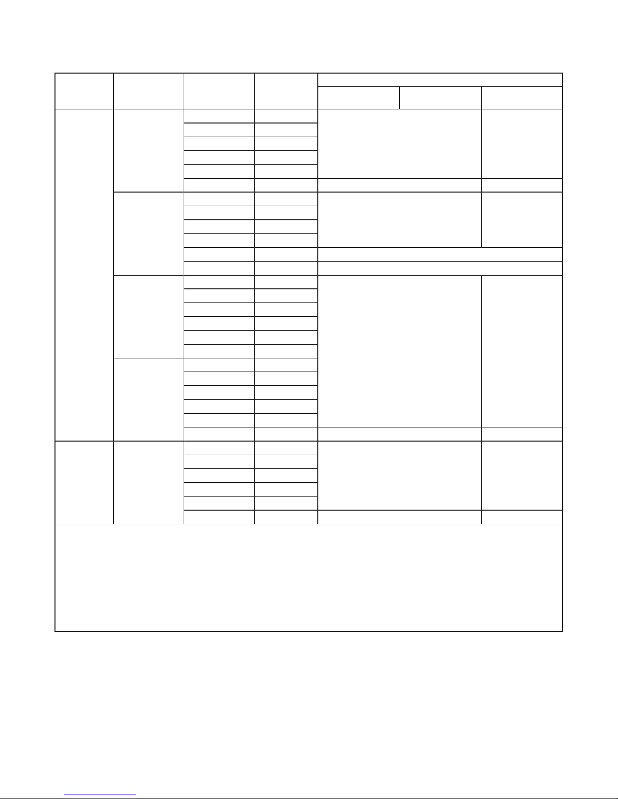
SPRINKLER
TYPE
ESCUTCHEON
TYPE
TEMPERATURE
RATI NG
BULB
COLOR CODE
NATURAL
BRASS
135° F (57 °C ) Orange
155° F (68° C) Red
STANDARD
175°F ( 7 9 °C) Yel l ow
200°F (93°C) Green
28 6°F (141°C ) Blue
360°F (182°C) Mauve 1, 2, 3, 6 1, 2, 6
135° F (57 °C ) Orange
155° F (68° C) Red
RECESSED
175°F ( 7 9 °C) Yel l ow
200°F (93°C) Green
28 6°F (141°C ) Blue 1, 2
PENDENT
(TY3255)
360°F (182°C) Mauve N/A
135° F (57 °C ) Orange
155° F (68° C) Red
DEEP
175°F ( 7 9 °C) Yel l ow
200°F (93°C) Green
28 6°F (141°C ) Blue
360°F (182°C) Mauve
135° F (57 °C ) Orange
155° F (68° C) Red
WITHOUT
175°F ( 7 9 °C) Yel l ow
200°F (93°C) Green
28 6°F (141°C ) Blue
360°F (182°C) Mauve 1, 2, 3 1, 2
135° F (57 °C ) Orange
155° F (68° C) Red
UPRIGHT
(TY3155)
WITHOUT
175°F ( 7 9 °C) Yel l ow
200°F (93°C) Green
28 6°F (141°C ) Blue
360°F (182°C) Mauve 1, 2, 3 1, 2
Notes:
1. Listed by Under write rs Lab orato ries, Inc. (UL), maximu m order l ength of 48 inche s
2. Listed by Unde rwr iters L aboratorie s for use in Canada (C-UL), m aximum order length o f 48 inches
3. A pprove d by FM Glob al (FM Ap provals), maxim um orde r length of 48 inch es
4. L oss Prevention C erti cati on Boar d (LPCB) a nd CE conformit y appl y to these te mper ature ra tings only
5. A pprove d by the Cit y of New York un der ME A 352-01-E
6. A pprove d by VdS
* Frame an d deec tor only
N/A – Not App licab le
TABL E A
SERIES DS-1 PENDENT & UPRIGHT DRY-TYPE SPRINKLERS, 5.6K, STANDARD RESPONSE
LABORATORY LISTINGS AND APPROVALS
SPRINKLER FINISH
CHROME
PL AT ED
POLYESTER*
1, 2, 3, 4, 5, 6 1, 2, 4, 5, 6
1, 2, 3, 5 1, 2, 5
1, 2, 3, 4, 5 1, 2, 4, 5
1, 2, 3, 4, 5 1, 2, 4, 5
Page 3
TFP500
DEFLECTOR
COMPRESSION
WRENCH
WRENCHING AREA
Page 3 of 10
SPRINKLER
TYPE
ESCUTCHEON
TYPE
TEMPERATURE
RATI NG
BULB
COLOR CODE
NATURAL
BRASS
SPRINKLER FINISH
CHROME
PL AT ED
135° F (57 °C ) Orange
155° F (68° C) Red
STANDARD
175°F ( 7 9 °C) Yel l ow
200°F (93°C) Green
28 6°F (141°C ) Blue
360°F (182°C) Mauve
135° F (57 °C ) Orange
155° F (68° C) Red
HSW*
(TY3355)
DEEP
175°F ( 7 9 °C) Yel l ow
200°F (93°C) Green
1**, 2**, 3***, 4, 5 1**, 2**, 4, 5
28 6°F (141°C ) Blue
360°F (182°C) Mauve
135° F (57 °C ) Orange
155° F (68° C) Red
WITHOUT
175°F ( 7 9 °C) Yel l ow
200°F (93°C) Green
28 6°F (141°C ) Blue
360°F (182°C) Mauve 1**, 2* *, 5 1**, 2* *
Notes:
1. Listed by Under write rs Lab orato ries, Inc. (UL), maximu m order l ength of 48 inche s
2. Listed by Unde rwr iters L aboratorie s for use in Canada (C-UL), m aximum order length o f 48 inches
3. A pprove d by FM Glob al (FM Ap provals), maxim um orde r length of 48 inch es
4. L oss Prevention C erti cati on Boar d (LPCB) a nd CE conformit y appl y to these te mper ature ra tings only
5. A pprove d by the Cit y of New York un der ME A 352-01-E
* Horizo ntal si dewall wi th top of deector-to -cei ling dis tance o f 4 to 12 inches (100 to 3 00 mm)
** Light and ordin ary ha zard o ccupa ncies o nly
*** Light hazard occupancies only
**** Fr ame and d eector only
TABL E B
SERIES DS-1 HORIZONTAL SIDEWALL (HSW) DRY-TYPE SPRINKLER, 5.6K, STANDARD RESPONSE
LABORATORY LISTINGS AND APPROVALS
POLYESTER***
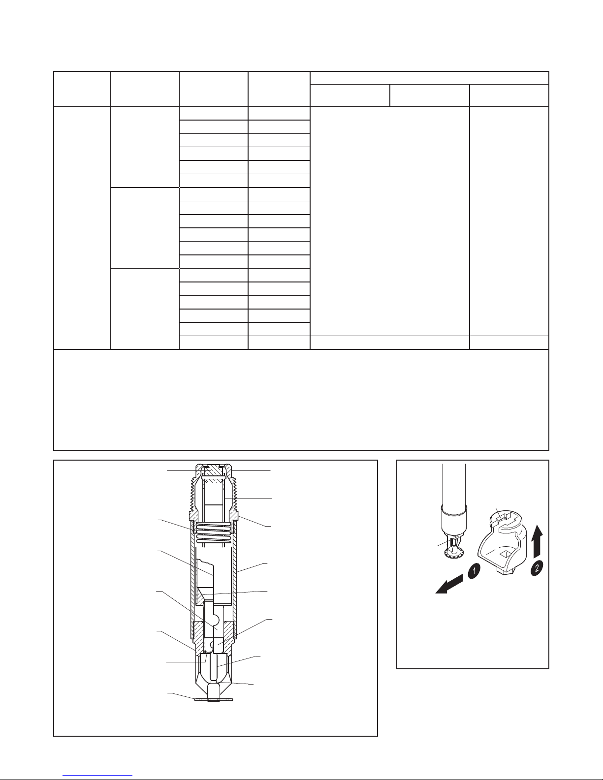
PLUG WITH
INLET
SEALING
ASSEMBLY
YOKE
SPRING
INLET
BAND
WATER
TUBE
GUIDE
CASING
INSERT
TUBE
BULB
FRAME
VENT HOLE
SEAT
5 mm BULB
SCREW
FIGURE 1
SERIES DS-1 DRY-T YPE SPRINKLER, 5.6K, STANDARD RESPONSE
AS SEM B LY
WRENCH
RECESS
FLAT
PUSH WRENCH
IN TO ENSURE
ENGAGEMENT
WITH SPRINKLER
FIGURE 2
W-T Y P E 7
WRENCH
Page 4

TFP500
(95,3 to 1219,2 mm)
SPRINKLER FITTING
(69,9 to 1219,2 mm)
SPRINKLER FITTING
(12,7 to 1168,4 mm)
SPRINKLER FITTING
(127,0 to 1219,2 mm)
SPRINKLER FITTING
CRITERIA SECTION)
SPRINKLER FITTING
(127,0 to 1219,2 mm)
Page 4 of 10
(REFER TO DESIGN
CRITERIA SECTION)
FACE OF
SPRINKLER
FITTING
ORDER LENGTHS:
2-3/4" to 48"
IN 1/4" (6,4 mm)
INCREMENTS
FACE OF
CEILING
2-3/16" ± 1/8"
(55,6 ± 3,2 mm)
1-3/4" DIA.
(44,5 mm)
3" DIA.
(76,2 mm)
FIGURE 3
PENDENT (TY3255)
WITH STANDARD ESCUTCHEON
(REFER TO DESIGN
CRITERIA SECTION)
FACE OF
SPRINKLER
FITTING
(REFER TO DESIGN
CRITERIA SECTION)
FACE OF
SPRINKLER
FITTING
ORDER LENGTHS:
3-3/4" to 48"
IN 1/4" (6,4 mm)
INCREMENTS
FACE OF
CEILING
1-3/8" ± 1/8"
(34,9 ± 3,2 mm)
2-1/4" DIA.
(57,2 mm)
2-7/8" DIA.
(73,0 mm)
FIGURE 4
PENDENT (TY3255)
WITH STANDARD
RECESSED ESCUTCHEON
ORDER LENGTHS:
DEFLECTOR
5" to 48"
SPRINKLER
ORDER LENGTHS:
IN 1/4" (6,4 mm)
INCREMENTS
(108,0 ± 3,2 mm)
TOP OF
(REFER TO DESIGN
CRITERIA SECTION)
FACE OF
FITTING
1/2" to 46"
FACE OF
CEILING
4-1/4" ± 1/8"
3-1/2" DIA.
(88,9 mm)
2-1/2" DIA.
(63,5 mm)
FIGURE 5
PENDENT (TY3255)
WITH DEEP ESCUTCHEON
ORDER LENGTHS:
5" to 48"
IN 1/4" (6,4 mm)
INCREMENTS
MINIMUM
1-3/4" (44,5 mm)
DEFLECTOR
TO CEILING
FIGURE 6
PENDENT (TY3255)
WITHOUT ESCUTCHEON
IN 1/4" (6,4 mm)
INCREMENTS
FACE OF
SPRINKLER
FITTING
(REFER TO DESIGN
FIGURE 7
UPRIGHT (TY3155)
WITHOUT ESCUTCHEON
Page 5

TFP500
CRITERIA SECTION)
OF WATERWAY
ORDER LENGTHS:
(76,2 mm)
(7,9 mm)
OF WATERWAY
2-1/4" (57,2 mm)
ORDER LENGTHS:
CRITERIA SECTION)
CRITERIA SECTION)
OF WATERWAY
ORDER LENGTHS:
(7,9 mm)
3-1/2" DIA.
Page 5 of 10
2-3/4" to 48" (69,9 to 1219,2 mm)
IN 1/4" (6,4 mm) INCREMENTS
FACE OF
SPRINKLER
FITTING
SPRINKLER FITTING
(REFER TO DESIGN
1/2" to 45-3/4" (12,7 to 1162,1 mm)
IN 1/4" (6,4 mm) INCREMENTS
FACE OF
SPRINKLER
FITTING
SPRINKLER FITTING
(REFER TO DESIGN
FACE OF
SPRINKLER
FITTING
SPRINKLER FITTING
(REFER TO DESIGN
FACE OF
MOUNTING
SURFACE
1-3/4" DIA.
(44,5 mm)
CENTERLINE
FIGURE 8
HORIZONTAL SIDEWALL (TY3355)
WITH STANDARD ESCUTCHEON
2-1/2" DIA.
(63,5 mm)
FACE OF
MOUNTING
SURFACE
CENTERLINE
FIGURE 9
HORIZONTAL SIDEWALL (TY3355)
WITH DEEP ESCUTCHEON
5-1/2" to 48" (139,7 to 1219,2 mm)
IN 1/4" (6,4 mm) INCREMENTS
FIGURE 10
HORIZONTAL SIDEWALL (TY3355)
WITHOUT ESCUTCHEON
2-3/8" ± 1/8"
(60,3 ± 3,2 mm)
3.5°
5/16"
4-1/4" ± 1/8"
(108,0 ± 3,2 mm)
3.5°
5/16"
DEFLECTOR TO
CENTERLINE
3" DIA.
(88,9 mm)
MINIMUM
MOUNTING
SURFACE
3.5°
5/16"
(7,9 mm)
Operation
When TYCO Series DS-1 5.6K Pendent,
Upright, and Horizontal Sidewall, Standard Response, Standard Coverage
Dry-type Sprinklers are in service,
water is prevented from entering the
assembly by the Plug with Sealing
Assembly (Ref. Figure 1) in the Inlet of
the sprinkler.
The glass bulb contains a fluid that
expands when exposed to heat. When
the rated temperature is reached, the
fluid expands sufficiently to shatter
the glass bulb, and the Bulb Seat is
released.
The compressed Spring is then able
to expand and push the Water Tube as
well as the Guide Tube outward. This
action simultaneously pulls inward on
the Yoke, withdrawing the Plug with
Sealing Assembly from the Inlet, allowing the sprinkler to activate and flow
wa ter.
Design
Criteria
TYCO Series DS-1 5.6K Pendent,
Upright, and Horizontal Sidewall, Standard Response, Standard Coverage
Dry-type Sprinklers are intended for
use in fire sprinkler systems designed
in accordance with the standard installation rules recognized by the applicable listing or approval agency (e.g., UL
Listing is based on NFPA 13 requirements). For more information on LPCB
Approval, contact Johnson Controls at
the following office:
Kopersteden 1
7547 TJ Enschede
The Netherlands
Tel: +31-(0)53-428-4444
Fax: +31-(0)53-428-3377
Sprinkler Fittings
Install 1 in. NPT Series DS-1 Dry-type
Sprinklers in the 1 in. NPT outlet or run
of the following fittings:
• malleable or ductile iron threaded
tee fittings that meet the dimensional requirements of ANSI B16.3
(Cl ass 150 )
• cast iron threaded tee fittings that
meet the dimensional requirements
of ANSI B16.4 (Class 125)
Do not install Series DS-1 Dry-type
Sprinklers into elbow fittings. The Inlet
of the sprinkler can contact the interior
of the elbow.
The unused outlet of the threaded tee is
plugged as shown in Figure 12.
Page 6

TFP500
Page 6 of 10
Temperatures for Heated Area
Ambient Temperature
Discharge End of Sprinkler
Notes:
1. For prote cted ar ea temperatur es that o ccur be tween v alues listed ab ove, use th e next co oler temperature.
2. These leng ths are inclusi ve of wind ve locities up to 30 m ph (18,6 kph).
Exposed to
40°F
(4°C)
30°F
(-1° C)
20°F
(-7° C)
10°F
(-12 ° C)
0°F
(-18 ° C)
-10°F
(-23°C)
-20°F
(-29°C)
-30°F
(-34°C)
-40°F
(-40°C)
-50°F
(-46°C)
-60°F
(-51°C)
40°F
(4°C)
Minimum Exposed Barrel Length
0 0 0
0 0 0
4
(100)
8
(200)
12
(305)
14
(355)
14
(355)
16
(405)
18
(455)
20
(510)
20
(510)
50°F
(10°C)
Inches
(mm)
0 0
1
(25)
3
(75)
4
(100)
6
(150 )
8
(200)
8
(200)
10
(255)
10
(255)
(1)
60°F
(16°C)
(2)
(100)
(100)
(150 )
(150 )
TABL E C
EXPOSED SPRINKLER BARRELS IN WET PIPE SYSTEMS
MINIMUM RECOMMENDED LENGTHS
You can also install Series DS-1 Drytype Sprinklers in the 1 inch NPT outlet
of a GRINNELL Figure 730 Mechanical
Tee and GRINNELL G-FIRE Figure 522;
however, the use of the Figure 730 Tee
and Figure 522 for this arrangement is
limited to wet pipe systems.
The configuration shown in Figure 13
is only applicable for wet pipe systems
where the sprinkler fitting and waterfilled pipe above the sprinkler fitting are
not subject to freezing and where the
length of the dry-type sprinkler has the
minimum exposure length depicted in
Figure 11. Refer to the Exposure Length
section.
For wet pipe system installations of 1
inch NPT Series DS-1 Dry-Type Sprinklers connected to CPVC piping, use
only the following TYCO CPVC fittings:
• 1 in. x 1 in. NPT Female Adapter (P/N
80145 )
• 1 in. x 1 in. x 1 in. NPT Sprinkler Head
Adapter Tee (P/N 80249)
For dry pipe system installations, use
only the side outlet of maximum 2-1/2
inch reducing tee when locating Series
DS-1 Dry-type Sprinklers directly
below the branchline; otherwise, use
the configuration shown in Figure 12 to
assure complete water drainage from
above Series DS-1 Dry-type Sprinklers and the branchline. Failure to do
so may result in pipe freezing and water
damage.
NOTICE
Do not install Series DS-1 Dry-type
Sprinklers into any other type fitting
without first consulting the Johnson
Controls Technical Services. Failure to
use the appropriate fitting may result in
one of the following:
•
failure of the sprinkler to operate
properly due to formation of ice
over the Inlet Plug or binding of the
Inlet Plug
•
insufficient engagement of the
Inlet pipe-threads with consequent
leakage
0
0
1
(25)
3
(75)
4
4
6
6
Drainage
In accordance with the minimum
requirements of the NATIONAL FIRE
PROTECTION ASSOCIATION for dry
,
pipe sprinkler systems, branch, cross,
and feed-main piping connected to Dry
Sprinklers and subject to freezing temperatures must be pitched for proper
drainage.
Exposure Length
When using Dry Sprinklers in wet pipe
sprinkler systems to protect areas
subject to freezing temperatures, use
Table C to determine a sprinkler’s
appropriate exposed barrel length to
prevent water from freezing in the connecting pipes due to conduction. The
exposed barrel length measurement
must be taken from the face of the
sprinkler fitting to the surface of the
structure or insulation that is exposed
to the heated area. Refer to Figure 11
for an example.
For protected area temperatures
between those given above, the
minimum recommended length from
the face of the fitting to the outside of
the protected area may be determined
by interpolating between the indicated
values.
Clearance Space
In accordance with NFPA 13, when
connecting an area subject to freezing and an area containing a wet pipe
sprinkler system, the clearance space
around the sprinkler barrel of dry-type
sprinklers must be sealed. Due to temperature differences between two
areas, the potential for the formation
of condensation in the sprinkler and
subsequent ice build-up is increased. If
this condensation is not controlled, ice
build-up can occur that might damage
the dry-type sprinkler and/or prevent
proper operation in a re situation.
Use of the Model DSB-2 Dry Sprinkler
Boot, described in technical data sheet
TFP591 and shown in Figures 14 and
15, can provide the recommended seal.
Page 7

TFP500
STRAP TIES
ESCUTCHEON
BOOT)
1-3/4" DIA.
DSB-2
FOR FREEZER
RUN
Page 7 of 10
FACE OF
SPRINKLER
FITTING
HEATED
AREA
DSB-2
INTENDED
FOR FREEZER
STRUCTURES
FIGURE 11
EXPOSURE LENGTH
EXPOSURE
LENGTH
(SEE DESIGN
CRITERIA
SECTION)
TO DRY
SYSTEM
AREA
SUBJECT
TO
FREEZING
FIGURE 12
SPRINKLER FITTING
UNHEATED AREA
(ENDS ON
OPPOSING
SIDES OF
BOOT)
DSB-2 BOOT
ADHESIVE
1-3/4" DIA.
(44,5 mm)
CLEARANCE
HOLE
INSULATED
FREEZER
STRUCTURE
DS-1
SHOWN WITH
STANDARD
OUTLET
PLUGGED
SPRINKLER
FITTING
(SEE DESIGN
CRITERIA
SECTION)
DSB-2
INTENDED
FOR FREEZER
STRUCTURES
(44,5 mm)
CLEARANCE
ADHESIVE
BOOT
STRAP TIES
(ENDS ON
OPPOSING
SIDES OF
HOLE
TO WET
SYSTEM
HEATED
AREA
DSB-2
INTENDED
STRUCTURES
FIGURE 13
SPRINKLER FITTING
HEATED AREA
INSULATED
FREEZER
STRUCTURE
DS-1
SHOWN WITH
STANDARD
ESCUTCHEON
SIDE
OUTLET
PLUGGED
SPRINKLER
FITTING
(SEE DESIGN
CRITERIA
SECTION)
MODEL DSB-2 DRY SPRINKLER
FIGURE 14
BOOT WITH PENDENT SERIES
DS-1 DRY-TYPE SPRINKLER
MODEL DSB-2 DRY SPRINKLER
FIGURE 15
BOOT WITH SIDEWALL SERIES
DS-1 DRY-TYPE SPRINKLER
Page 8

TFP500
Page 8 of 10
Installation
TYCO Series DS-1 5.6K Pendent,
Upright, and Horizontal Sidewall, Standard Response, Standard Coverage
Dry-type Sprinklers must be installed
in accordance with this section.
General Instructions
Series DS-1 Dry-type Sprinklers must
only be installed in fittings that meet
the requirements of the Design Criteria section. Refer to the Design Criteria
section for other important requirements regarding piping design and
sealing of the clearance space around
the Sprinkler Casing.
Do not install any bulb-type sprinkler
if the bulb is cracked or there is a loss
of liquid from the bulb. With the sprinkler held horizontally, a small air bubble
should be present. The diameter of the
air bubble is approximately 1/16 inch
(1,6 mm) for the 135°F (57°C) rating to
1/8 inch (3,2 mm) for the 360°F (182°C)
rating.
Obtain a leak-tight 1 inch NPT sprinkler
joint by applying a minimum-to-maximum torque of 20 to 30 lb-ft (26,8 to
40,2 N·m). Higher levels of torque may
distort the sprinkler Inlet with consequent leakage or impairment of the
sprinkler.
Do not attempt to compensate for
insufficient adjustment in an Escutcheon Plate by under or over-tightening
the Sprinkler. Re-adjust the position of
the sprinkler fitting to suit.
Notes:
• Install pendent sprinklers only in
the pendent position; install upright
sprinklers only in the upright position. The deflector of a pendent or
upright sprinkler is to be parallel to
the ceiling.
• Install horizontal sidewall sprinklers
in the horizontal position with their
centerline of waterway perpendicular to the back wall and parallel to
the ceiling. Ensure the word “TOP”
on the Deflector faces the ceiling.
Step 1. With a non-hardening pipethread sealant such as TEFLON applied
to the inlet threads, hand-tighten the
sprinkler into the sprinkler fitting.
Step 2. Wrench-tighten the sprinkler
using either:
• a pipe wrench on the Inlet Band or
the Casing (Ref. Figure 1)
• the W-Type 7 Sprinkler Wrench on
the Wrench Flat (Ref. Figure 2)
Apply the wrench recess of the W-Type
7 Sprinkler Wrench to the wrench flat.
Note: If sprinkler removal becomes
necessary, remove the sprinkler using
the same wrenching method noted
above. Sprinkler removal is easier when
a non-hardening sealant was used
and torque guidelines were followed.
After removal, inspect the sprinkler for
damage.
Step 3. After installing the ceiling or
wall and applying a ceiling finish, slide
on the outer piece of the escutcheon until it comes in contact with the
ceiling/wall. Do not lift the ceiling panel
out of its normal position.
When using the Deep Escutcheon,
hold the outer piece in contact with the
mounting surface (ceiling or wall). Then
rotate the inner piece approximately 1/4
turn with respect to the outer piece,
to hold the Deep Escutcheon firmly
to gethe r.
Care and
Maintenance
TYCO Series DS-1 5.6K Pendent,
Upright, and Horizontal Sidewall,
Standard Response, Standard Coverage Dry-type Sprinklers must be maintained and serviced in accordance with
this section.
Before closing a fire protection system
main control valve for maintenance
work on the fire protection system
that it controls, obtain permission to
shut down the affected fire protection
systems from the proper authorities
and notify all personnel who may be
affected by this action.
Absence of the outer piece of an
escutcheon, which is used to cover a
clearance hole, may delay the time to
sprinkler operation in a fire situation.
A Vent Hole is provided in the Bulb
Seat (Ref. Figure 1) to indicate if the Dry
Sprinkler is remaining dry. Evidence of
leakage from the Vent Hole indicates
potential leakage past the Inlet seal
and the need to remove the sprinkler
to determine the cause of leakage;
for example, an improper installation
or an ice plug. Close the fire protection system control valve and drain the
system before removing the sprinkler.
Sprinklers which are found to be
leaking or exhibiting visible signs of
corrosion must be replaced.
Automatic sprinklers must never be
painted, plated, coated, or otherwise altered after leaving the factory.
Modified sprinklers must be replaced.
Sprinklers that have been exposed to
corrosive products of combustion, but
have not operated, should be replaced
if they cannot be completely cleaned
by wiping the sprinkler with a cloth or
by brushing it with a soft bristle brush.
Care must be exercised to avoid
damage to the sprinklers before,
during, and after installation. Sprinklers damaged by dropping, striking,
wrench twist/slippage, or the like, must
be replaced. Also, replace any sprinkler that has a cracked bulb or that has
lost liquid from its bulb (Ref. Installation section).
The owner is responsible for the inspection, testing, and maintenance of their
fire protection system and devices in
compliance with this document, as well
as with the applicable standards of the
NATIONAL FIRE PROTECTION ASSOCIATION (e.g., NFPA 25), in addition to
the standards of any other authorities
having jurisdiction. Contact the installing contractor or product manufacturer
with any questions.
Automatic sprinkler systems are recommended to be inspected, tested,
and maintained by a qualified Inspection Service in accordance with local
requirements and/or national codes.
Page 9

P/ N* 60 – XXX – X – XXX
TFP500
Page 9 of 10
SIN
96
Standard Escutcheon (1 in. NPT )
93
97
Recessed Escutcheon (1 in. NPT)
92
94
Standard Escutcheon (1 in. NPT )
53
54
98
Notes:
1. Escutc heon Finish applies to sprinklers pr ovided w ith esc utcheons.
2. 360°F (182°C) tem perature rati ng applies to non -rece ssed s prink ler
assemblies.
3. D ry-t ype Sp rinklers are f urnis hed bas ed upon “Order Length” as measured p er Figures 3 thro ugh 10, as applicab le, and fo r each in dividual
sprinkler where it is to b e insta lled. Af ter the m easur ement i s taken,
round it to the near est 1/4 inch in creme nt.
* Use Pre x “I” for IS O 7-R 1 Connection (e.g., I-60 -961-1-180).
Pendent with
Pendent with
Deep Escutcheon (1 in. NPT)
Pendent with
Pendent without
Escutcheon (1 in. NPT)
Sidewall with
Sidewall with
Deep Escutcheon (1 in. NPT)
Sidewall without
Escutcheon (1 in. NPT)
Upright without
Escutcheon (1 in. NPT)
TY3255
(Figure 3)
TY3255
(Figure 5)
TY3255
(Figure 4)
TY3255
(Figure 6)
TY3355
(Figure 8)
TY3355
(Figure 9)
TY3355
(Figure 10)
TY3155
(Figure 7)
SPRINKLER
FINISH
0
1
2
4
9
TEMPERATURE
0 135° F (57 °C)
1 155°F ( 68°C)
2 175°F ( 7 9 °C)
3 200°F (93°C)
4 28 6°F (141°C )
5 360°F (182°C)
CHROME
PL AT E D
NAT U R A L
BRASS
NAT U R A L
BRASS
SIGNAL WHITE
(RAL9003)
POLYESTER
CHROME
PL AT E D
RATI NG
(2)
ESCUTCHEON
SIGNAL WHITE
POLYESTER
SIGNAL WHITE
POLYESTER
SIGNAL WHITE
POLYESTER
055 5.50 in.
082 8.25 in.
180 18.00 in.
187 18.75 in.
372 37. 25 i n .
480 48.00 in.
(1)
FINISH
(RAL9003)
(RAL9003)
BRASS
PL AT E D
(RAL9003)
CHROME
PL AT E D
ORDER
LENGTH
(3)
SERIES DS-1 DRY-T YPE SPRINKLERS, 5.6K, STANDARD RESPONSE
Limited
Warranty
For warranty terms and conditions, visit
www.tyco-fire.com.
Ordering
Procedure
Contact your local distributor for availability. When placing an order, indicate the full product name, including
description and part number (P/N).
Dry-type Sprinklers
When ordering Series DS-1 5.6K
Pendent, Upright, and Horizontal Sidewall, Standard Response, Standard
Coverage Dry-type Sprinklers, specify
the following information:
TABL E D
PART NUMBER SELECTION
• SIN:
TY3255 – Pendent
TY3155 – Upright
TY3355 – Horizontal Sidewall
• Order Length:
Dry-type Sprinklers are furnished
based upon Order Length as measured per Figures 3 through 10, as
applicable. After the measurement is
taken, round it to the nearest 1/4 inch
increment.
• Inlet Connections:
1 Inch NPT
(Standard)
ISO 7-R 1
(For information on ISO Inlet Thread
Connections, contact your Johnson
Controls Sales Representative.)
• Temperature Rating
• Sprinkler Finish
• Escutcheon Type and Finish, as
applicable
• P/N from Table D
Part numbers are for 1 inch NPT
standard order sprinklers. Orders
for all other sprinkler assemblies
must be accompanied by a complete
description.
Sprinkler Wrench
Specify W-Type 7 Sprinkler Wrench,
P/N 56-850-4-001
Sprinkler Boot
Specify Model DSB-2 Dry Sprinkler
Boot, P/N 63-000-0-002
This part number includes one (1) Boot,
two (2) Strap Ties, and 1/3 oz. of Adhesive (a sufficient quantity for installing
one boot).
Page 10

TFP500
Page 10 of 10
1400 Pennbr ook Parkway, Lansdale, PA 19446 | Tel epho ne +1-215-3 62- 0700
© 2018 John son Control s. All right s reserved. A ll specifica tions and ot her informa tion shown wer e current as o f document rev ision date an d are subject t o change wit hout notice.
NATIONAL FIRE P ROTECTION ASSOCIATIO N and NFPA are register ed trademarks of N ational Fire Protec tion Associati on;
TEFLON is a regi stered tradema rk of DuPont
 Loading...