

Page 1
Digital Security Controls
TL880LTB Dual Path Controller
TL880LEBDual Path Controller
TL880LEAT-LAT Dual Path Controller
TL880LEAT-PE Dual Path Controller
WARNING: This manual contains information on limitations regarding product use and function and
information on the limitations as to liability of the manufacturer. The entire manual should be carefully
read.
Page 2

Introduction 5
Features 5
Communicator ratings 6
Communicator compatibility 6
ULInstallation Requirement s 7
Installation 8
Tools and supplies required 8
Step 1: Enable module 9
Step 2: Connecting the module 9
Step 3: Verify installer code t o activate Alarm.com module 10
Step 4: Perform dual-path test (module registration) 10
Step 5: Allow module t o auto-program 11
Panel settings 11
Troubleshooting 14
Module status information 14
Troubleshooting LEDs 14
Various module states (modes) 17
Improving wireless signal strength 17
Walking t he customer through new user set up on the web 18
Interactive Service Menu 19
Interactive menus 19
Installer programming 19
User functions 19
Limited Warranty 21
End User License Agreement 21
Regulatory Information 23
- 2 -
Page 3

Warning: Installer Please Read Car efully
Note to installers
The wa rnings on this page contain vital inf ormation. As the only individual in conta ct with system user s, it is the installer’s r esponsibility to br ing
each item in this wa rning to the attention of all use rs of this system.
System failures
This system has be en ca ref ully designed to be a s e ffe ctive as possible. There ar e cir cumstance s, howe ver, involving fire, burgla ry, or other types
of eme rgenc ies w here it may not provide protection. A ny a larm system of any type may be compromised deliber ately or may f ail to oper ate a s
expected for a var iety of r ea sons. Some, but not all, of the r easons may be :
Access by intruders
Intruders ma y e nter through an unpr otected a ccess point, circ umvent a sensing devic e, eva de dete ction by moving through an ar ea of insufficient
coverage , disconne ct a wa rning device , or interfe re with or prevent the prope r oper ation of the system.
Component failure
Although e very e ffort ha s be en made to make this system a s r eliable a s possible, the system may fa il to f unction a s intende d due to the failure of a
component.
Compromise of radio frequency (Wireless)
A device 's signals may not r eac h the re ceive r under a ll circumstance s, whic h c ould include: metal objec ts plac ed on or ne ar the r adio pa th,
delibera te jamming or othe r inadver tent r adio signal interfer ence .
Criminal knowledge
This system conta ins sec urity f eature s w hich w ere known to be eff ective a t the time of ma nufac ture. It is possible for persons with cr iminal intent
to de velop technique s which re duce the eff ectiveness of these fe ature s. It is important that your secur ity system be re viewed pe riodically to
ensure that its fe atures r emain effec tive a nd tha t it is update d or r eplac ed if it is found that it doe s not provide the protec tion expe cted.
Failureof replaceable batteries
This system’s wire less transmitters have been de signed to provide sever al ye ars of ba ttery life under nor mal c onditions. The e xpecte d ba ttery life
is a f unction of the device environme nt, usage , a nd type . Ambient conditions suc h a s high humidity, high or low temper atures, or large temperature
fluctuations may re duce the expec ted batter y life . W hile e ach tra nsmitting device has a low ba ttery monitor whic h identifie s whe n the batterie s
need to be replace d, this monitor ma y f ail to oper ate a s e xpecte d. Regular te sting and maintena nce will kee p the system in good opera ting
condition.
Inadequate installation
A sec urity system must be installed pr operly in or der to provide adequa te protec tion. Eve ry installation should be eva luated by a sec urity
profe ssional to ensure that all a cc ess points and a rea s a re c overe d. Loc ks a nd latches on windows and door s must be sec ure and ope rate a s
intended. Windows, door s, wa lls, ce ilings and other building mater ials must be of suffic ient stre ngth a nd c onstruction to provide the level of
protec tion expe cted. A r eeva luation must be done during a nd a fter a ny c onstruction activity. A n e valuation by the fire and/or police de partment is
highly re commended if this se rvice is ava ilable.
Inadequate t esting
Most proble ms that would preve nt a n a larm system from oper ating a s intende d can be found by regula r testing a nd maintenance . The complete
system should be tested we ekly and immediately a fter a brea k-in, an attempted br eak- in, a fire, a storm, a n e arthqua ke, an a ccident, or a ny kind
of construc tion ac tivity inside or outside the pr emises. The testing should include a ll sensing devic es, keypa ds, c onsoles, a larm indicating device s,
and any othe r opera tional de vices that ar e par t of the system.
Insufficient time
There may be c ircumstance s w hen the system will oper ate a s intende d, ye t the oc cupants will not be protecte d f rom a n e merge ncy due to their
inability to r espond to the warnings in a timely manner . I f the system is re motely monitored, the r esponse may not occ ur in time to prote ct the
occupants or their belongings.
Motion detectors
Motion dete ctors ca n only dete ct motion within the de signated ar eas a s shown in their re spective installation instruc tions. They c annot discriminate
between intruders a nd intende d oc cupa nts. Motion de tectors do not pr ovide volumetric area protection. They ha ve multiple be ams of detec tion and
motion ca n only be de tecte d in unobstructe d a rea s c overe d by these bea ms. They c annot detec t motion w hich occ urs be hind walls, ce ilings, floors,
closed doors, glass pa rtitions, glass door s or windows. A ny type of tampering whe ther intentional or unintentional such as masking, painting, or
spraying of a ny ma terial on the lenses, mirror s, windows or a ny othe r part of the de tection system w ill impair its prope r operation. Passive infr are d
motion detec tors opera te by sensing cha nges in temperature . Howe ver their e ffe ctiveness c an be re duce d when the ambient temper ature rises
near or above body te mperatur e or if ther e ar e intentional or unintentional sourc es of he at in or ne ar the detec tion ar ea. Some of these heat
source s c ould be he ater s, r adiators, stoves, bar becue s, f ireplac es, sunlight, stea m vents, lighting and so on.
Power failure
Control units, intrusion detec tors, smoke detec tors a nd many other se curity device s r equire a n adequate powe r supply for proper opera tion. If a
device opera tes from batteries, it is possible f or the batter ies to fa il. Eve n if the ba tteries ha ve not f ailed, they must be char ged, in good condition
and installed cor rec tly. If a device operates only by AC power, a ny interruption, howeve r brie f, will re nder tha t devic e inopera tive while it doe s
not ha ve power. Powe r interruptions of any length are ofte n a ccompa nied by voltage fluctua tions which may da mage ele ctronic e quipment such
as a se curity system. Af ter a pow er inter ruption ha s occurre d, immediately conduct a c omplete system te st to e nsure tha t the system oper ates as
intended.
Security and insurance
Regardless of its ca pabilities, an a larm system is not a substitute f or prope rty or life insuranc e. An ala rm system a lso is not a substitute for pr operty
owner s, re nters, or othe r occ upants to ac t pr udently to pre vent or minimize the har mful e ffe cts of an eme rgenc y situation.
- 3 -
Page 4

Smokedetectors
Smoke de tectors that ar e a pa rt of this system may not properly a lert occ upants of a fire for a number of r easons, some of w hich f ollow. The
smoke detec tors ma y ha ve bee n imprope rly installed or positioned. Smoke may not be able to re ac h the smoke de tectors, such a s whe n the fire is
in a chimney, wa lls or roof s, or on the othe r side of closed doors. Smoke dete ctors may not detec t smoke f rom f ires on another le vel of the
residence or building. Ever y fire is diff ere nt in the amount of smoke produc ed and the r ate of bur ning. Smoke dete ctors ca nnot sense all type s of
fires equa lly we ll. Smoke detec tors ma y not provide timely warning of f ires ca used by ca rele ssness or safe ty haz ards suc h a s smoking in be d,
violent e xplosions, esca ping ga s, imprope r storage of flammable ma terials, over loaded electrica l c ircuits, c hildren playing with ma tches, or a rson.
Even if the smoke de tector ope rate s a s intende d, ther e may be c ircumstanc es when the re is insufficient wa rning to a llow a ll occ upants to e scape
in time to avoid injury or dea th.
Telephone lines
If tele phone lines are used to transmit a larms, they may be out of se rvice or busy f or ce rtain periods of time. Also a n intruder may c ut the
telephone line or defe at its oper ation by more sophisticated mea ns which may be difficult to de tect.
Warning d evices
Warning de vices such a s sire ns, be lls, horns, or strobe s may not wa rn people or wake n someone sleeping if there is a n inter vening w all or door. If
war ning devic es ar e locate d on a differ ent level of the residenc e or pr emise, then it is less likely tha t the oc cupants will be aler ted or awa kened.
Audible war ning de vices may be inter fer ed with by othe r noise source s suc h a s ster eos, ra dios, televisions, air c onditioners, other a ppliance s, or
passing tr affic . A udible wa rning device s, how ever loud, may not be he ard by a hear ing-impaired pe rson.
IMPORTANT
This installation manual shall be used in conjunction with the control panel installation manual available online
from the DSC website at www.dsc.com. All the safety instructions specified within that manual shall be
observed. The control panel is referenced as the “panel” throughout this document. This installation guide
provides the basic wiring, programming and troubleshooting information.
The alar m communicator is a f ixed, wall-mounted unit, and shall be installed in the location specified in these
instructions. The equipment enclosure must be fully assembled and closed, with all the necessary screws/tabs,
and secured to a wall before operation. Internal wiring must be routed in a manner that prevents:
l Excessive strain on wire and on terminal connections.
l Interf erence between power limited and non power limited wiring.
l Loosening of terminal connections.
l Damage to the conductor insulation.
Safety information
The installer must instruct the system user on each of the following:
l Do not attempt to service this product. Opening or removing covers may expose the user to dangerous
voltages or other risks.
l Any servicing shall be referred to skilled persons only.
l Use authorized accessories only with this equipment.
l Do not stay close to the equipment during device operation.
l Do not touch the external antenna.
Safety instructions for skilled workers
When using equipment connected to the telephone network, always f ollow the basic safety instructions
provided with this product. Save these instructions for future r eference.
Follow all WARNINGS AND INSTRUCTIONS specif ied within the manual of the alarm controller.
Do NOT connect this equipment to electrical outlets controlled by wall switches or automatic timers.
AVOID installing equipment near heaters, air conditioners, ventilators, and refrigerators.
AVOID locating equipment close to or on top of lar ge metal objects, for example wall studs.
Safety precautions required during installation
NEVER install this equipment during a lightning storm.
Position cables so that accidents cannot occur.
- 4 -
Page 5

This equipment must be installed and used within an environment that provides the pollution degree max 2 and
over-voltages category II NONHAZARDOUS LOCATIONS, indoor only. The equipment is designed to be
installed, serviced and/or repaired by Skilled Persons only; (skilled person is defined as a person having the
appropriate technical training and experience necessary to be aware of hazards to which that person may be
exposed in performing a task and of measures to minimize the risks to that person or other persons).
Before installing/servicing, DISCONNECT the power and the telephone line of the alarm controller.
These safety instructions should not prevent you from contacting the distributor and/or the manufacturer to
obtain any further clarification and/or answers to your concerns.
Introduction
This guide provides installation and operating instructions for the Alarm.com communicator module. The
following sections offer you a brief overview of its capabilities. Some capabilities and features vary based on
the Alarm.com service plan selected. Visit www.alarm.com/Dealer or contact Alarm.com for more
information.
Note: The Dual Path IP/L TE module is available in the model TL880LTB/TL880LEB/TL880LEATLAT /TL880LEAT-PE.
The module contains the IP/Radio subassembly model ADC-620T and the PC-Link to RS422 conversion
interface. The module is compatible with PowerSeries Neo Alarm Control Unit models HS2128, HS2064,
HS2032 and HS2016 software versions 1.1 and above and PowerSeries Pro Alarm Control Unit models
HS3032, HS3128, and HS3248 software versions 1.0 and above.
The module enables wireless reporting of all alarms and other system events from the PowerSeries Neo and
PowerSeries Pro control panel using an all-digital, LTE wireless (cellular) network or an Ethernet network.
The module can be used as the primary communication path for all alarm signaling, or as a backup to a
telephone connection to the central monitoring station. The wireless alarm signaling and routing service is
operated by Alarm.com. The module also features integrated support for Alarm.com’s home automation
solution with built-in Z-Wave capabilities.
Note: Alarm.com's home automation solution with built-in Z-Wave capabilities is not UL evaluated.
Contact information
For additional information and support on Alarm.com modules, initial account setup, home automation, and all
other Alarm.com products and services, please visit: www.Alarm.com/dealer or contact Alarm.com technical
support at: 1-866-834-0470.
Features
l 128-bit AES encryption via cellular and I nternet.
l Models TL880LTB and TL880LEAT-LAT have NI ST validation certificate number 4684.
l Models TL880LEB and TL880LEAT-PE have NISTvalidation certificate number 5100.
l Back up or primary cellular alarm communication and Ethernet.
l Remote firmwar e upgrade via cellular or Internet using Alarm.com management portal.
l Full event reporting to central station.
l Cellular periodic test transmission.
l Integrated call r outing.
l Panel remote uploading/downloading support via cellular or Internet.
l PC-LINK connection.
l Programmable labels.
l SIA and Contact ID (CID) formats supported.
l Signal strength and trouble display LE Ds.
l Subscriber Identity Module (SIM) card included with communicator.
- 5 -
Page 6
l Supervision heartbeats over Ethernet path or over the Cellular path, when the E thernet path is known to be
in a trouble condition.
l 2-way audio capable when used with audio module HSM2955(R) - Refer to HSM2955(R) manual.
Communicator ratings
Model
TL880LTB and
TL880LEAT-LAT
Power supply ratings
11.3V - 12.5V DC
Input Voltage
(provided by c ompatible DSC
control panel)
Current consumptio n
Standby Current (Average Value) 150mA
Alarm (Transmitting) Current (Peak Value) 400mA
Cellular Network
TL880LTB: LTE Verizon
TL880LEAT-LAT:LTE AT&T
TL880LTB: 700 / AWS1700MHz
Operating Frequency
TL880LEAT-LAT: LTE bands 1,
2, 3, 4, 5, 7, 28
Environmental specifications
Operating Temperature 32°F to 120°F (0°C to 49°C)
Storage Temperature -34°C t o 60°C
Humidity 93%RH non-condensing
Mechanical specifications
Dimensions 6" x 8.9" x 1.3"
Weight 365g
Communicator compatibility
Communicator
TL880LTB
TL880LEB
TL880LEAT-LAT
TL880LEAT-PE
Receiver/
Panel
Receiver
Panel
Description
l Sur-Gard System I-IP Receiver, version 1.13+
l Sur-Gard System II Receiver, version 2.10+
l Sur-Gard SG-DRL3-IP, version 2.30+(for Sur-Gard System I II Receiver)
l Sur-Gard SG-DRL4-IP version 1.20+ (for Sur-GardSystem IV Receiver)
l Sur-Gard SG-DRL5-IP version 1.00+ (for Sur-GardSystem 5 Receiver)
l HS2016, version 1.1+
l HS2032, version 1.1+
l HS2064, version 1.1+
l HS2128, version 1.1+
TL880LEB and
TL880LEAT-PE
TL880LEB: LTE AT&T/T elus
TL880LEAT-PE: LTEAT&T
TL880LEB: 1700/1900
AWS700/850MHz
TL880LEAT-PE: LTE bands 1,
2, 3, 4, 5, 7, 28
l HS3032, version 1.0+
l HS3128, version 1.0+
l HS3248, version 1.0+
Note: Enter [*][8][Installer Code][900][000] at keypad to view the panel version number.
Products or components of products, which perform communications functions only shall comply with the
requirements applicable to communications equipment as specified in UL60950-1, Information Technology
Equipment - Safety - Part 1: General Requirements. Such components include, but are not limited to: hubs;
routers; NIDs; third-party communications ser vice providers; DSL modems; and cable modems.
- 6 -
Page 7

ULInstallation Requirements
Note: For equipment used at the protected premises and intended to facilitate IPcommunications (hubs,
routers, NI Ds, Digital Subscriber Line (DSL), cable models), 24-hour back-up power is r equired. Where such
cannot be facilitated, a secondary (back-up) communication channel is required.
Domain Name Servic e (DNS) programming i s not permitted i n UL1610 and ULC-S304 listed
sy stems.
- 7 -
Page 8
Installation
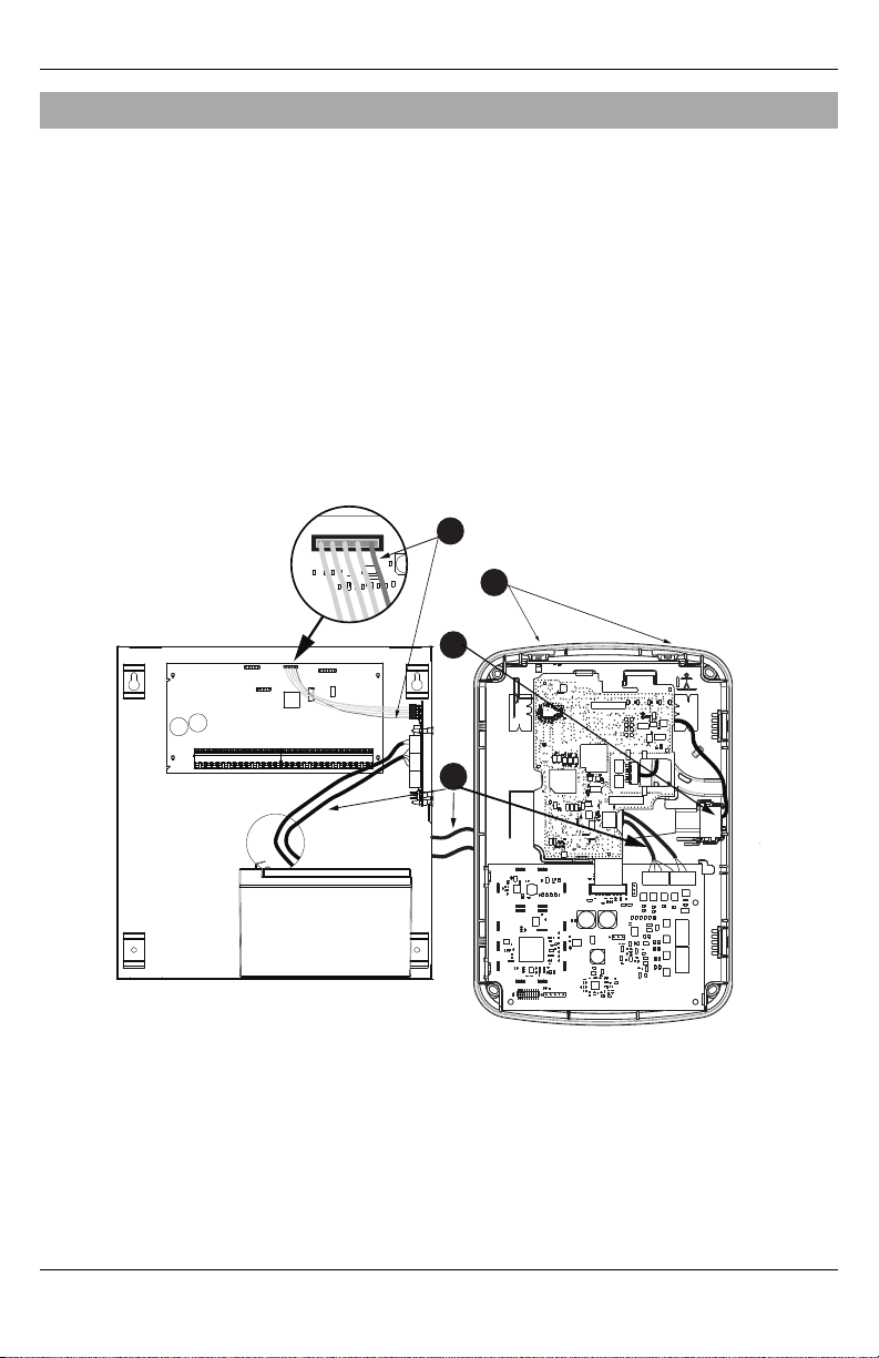
Alarm controller PCB
PCLINK_2
Alarm Controller Cabinet
TL880LTB/TL880LEB
/TL880LEA
T-LAT/TL880LEAT-PE controller
A
B
D
C
INSTALLATION
Follow these guidelines during installation.
l Before affixing the communicator to a wall, verify the LT E signal level at the installation location. On a
keypad, press and hold the 5 key for 2 seconds to view the LTE signal level. An installation location with
a sustained signal level of two or more bars is recommended.
l When using panel power for the module, do not exceed the panel's maximum rated total output power.
Refer to the specific panel installation instructions for details. Only one module can be used per panel.
l Do not mount the module inside of the metal alarm panel enclosure.
Tools and supplies required
You will need the following tools and supplies:
l Small flat-head and Phillips screwdrivers
l Screws (included)
l Antenna (included)
l 16 pin ribbon cable (included)
- 8 -
Page 9

PCL-422
Mounted in Alarm Controller Cabinet
Controller Board
RX-
RX+
TX+
TX-
+12V
GND
+12V
GND
E
F
A Red wire on alarm controller PCLink2 Header
B Antennaaccess ports
C Ethernet cable
D Quad cables (100' / 30m maximum)
E Red wire on PCL-422 PCLink Header
F LTE Controller Board power t erminals. Can be connected to power s upply module.
Installation
Step 1: Enable module
For the Alarm.com module to communicate with the panel, section [382] option 5 at the panel must be set to
ON. T his section is OFF by default and must be enabled for the system to function properly. This should be
done before connecting the PC-Link cable to power up the module to ensure all initialization commands are
processed properly.
Step 2: Connecting the module
Caution: Power down the alarm panel by removing both AC and the battery prior to connecting the module.
1: Connect data bus
The maximum cable length permitted for the data bus is 100ft/30m.
l Connect the RX+ terminal on the module to the TX+ terminal on the PCL-422
l Connect the RX- terminal on the module to the TX- terminal on the PCL-422
l Connect the TX- terminal on the module to the RX- terminal on the PCL-422
l Connect the TX+ terminal on the module to the RX+ terminal on the PCL- 422
2: Connect power
- 9 -
Page 10

Installation
The maximum cable length permitted for the power connection is 100ft/30m.
l Connect the GND terminal on the module to the GND terminal on the PCL- 422
l Connect the +12V terminal on the module to the +12V terminal on the PCL-422
3:Connect the PC-Link cable
Note: To ensure correct orientation, refer to items A and D in the wiring diagrams for the proper position of
the red wire on the PC-link cable.
l Connect one end of the supplied PC-Link cable to the PC-Link header on the PCL-422
l Connect the other end of the PC-L ink cable to the PC-LINK_2 header on the alarm panel
4: Connect Ethernet (optional)
Note: Refer to item C in the wiring diagram for the correct placement of the Ether net cable.
l Connect one end of the Ethernet cable to the Ethernet port on the communicator
l Connect the other end of the Ethernet cable to the E thernet port on the router
5: Connect remote external antennas (optional)
Remote external antennas are available for the module if there is inadequate cellular r eception at the preferred
mounting location. Contact DSC technical support for antenna options.
The module has two covered access ports on the top of the enclosure. Remove the plastic tab covering the
desired port and either mount the antenna on the enclosure or use the opening to pass through the antenna cable.
Note: Due to the curvature of the enclosure, the plastic port covers are NOT interchangeable. Ensure that any
unused ports are covered with their original plastic tab.
Warning: The external antenna must be installed in a manner to prevent end users fr om accessing any
conductive part of the anntena or antenna cable ( i.e., recessed mounting or equivalent).
6: Power up
Connect panel battery and AC power.
Step 3: Verify installer code to activate Alarm.com module
Alarms and other signals will not be sent to Alarm.com until the installer code is verified. To activate the
account, perform the following steps:
1. Press [*][8] to enter Installer Programming.
2. Enter the installer code.
3. Press [#] to exit Installer Programming.
To remotely activate a system that is already signaling, perform the following steps:
1. Go to www.alarm.com/dealer.
2. Go to the customer's account.
3. Select the error message at the top of the page.
4. Enter the installer code.
Step 4: Perform dual-path test (module registration)
To initiate module communication with Alarm.com and the cellular network for the first time, perform a
“Dual-Path phone test”. Note that the test can also be used at any time by the installer to force communication
with Alarm.com. To test the cellular path, press and hold [3] for two seconds. To test the broadband path,
press and hold [4] for two seconds. A Dual-Path test can also be completed through the Interactive Services
menu. To perf orm the Dual-Path test, press [*][ 6] followed by the master code and [04].
- 10 -
Page 11

Installation
The panel indicates when the test has completed by activating the siren output on medium volume for 2 seconds
followed by full volume for 2 seconds. However, if the test was initiated via the [3] or [4] key, or through the
Interactive Services menu, the siren will not sound. All display lights and LCD pixels turn on. This indicates
that Alarm.com has received and acknowledged the signal. This does not guarantee that the signal went
through to a central station; it confirms that Alarm.com’s Network Operations Center received the signal. The
central station should be contacted directly to verify that the signal was received on the correct account and
that the central station routing settings have been set up correctly. If the signal does not go through to the
central station, the panel displays a “Failure to Communicate” message. Double check the account’s central
station Forwarding Settings on Alarm.com and contact technical support if the trouble persists.
Step 5: Allow module to auto-program
After a successful dual-path test, wait 2 minutes for the module to automatically program and initialize before
entering the I nstaller Programming menus. Entering Installer Programming during module initialization will
cancel the process. LCD keypads display a message indicating when auto-programming is occurring and when
it has completed. During the auto-programming session, the module automatically programs panel settings
required for proper functionality with Alarm.com as noted in the “Panel Settings” section.
Panel settings
Central station and telephone line settings
Central Station (CS) and telephone line settings will be automatically configured through the CS Forwarding
Settings page of the Alarm.com Dealer Site. The following are the panel settings that are configured through
the Dealer Site page (when required) and should not be configured in the panel:
Section Opt ion Description
015 7 Telephone line monitoring
300 [001] -- Panel Communication Path - Receiver 1
300 [002] -- Panel Communication Path - Receiver 2
300 [003] -- Panel Communication Path - Receiver 3
300 [004] -- Panel Communication Path - Receiver 4
301 [001] -- Communication telephone number 1
301 [002] -- Communication telephone number 2
301 [003] -- Communication telephone number 3
301 [004] -- Communication telephone number 4
309 [001] -- System Call Direction - Maintenance
309 [002] -- System Call Direction - Test Transmission
310 [000] -- System account number
310 [001] -- Partition 1 account number
310 [002] -- Partition 2 account number
310 [003] -- Partition 3 account number
310 [004] -- Partition 4 account number
310 [005] -- Partition 5 account number
310 [006] -- Partition 6 account number
310 [007] -- Partition 7 account number
310 [008] -- Partition 8 account number
- 11 -
Page 12

Installation
Section Opt ion Description
311 [001] -- Partition 1 Call Direction - Alarm/Restore
311 [002] -- Partition 1 Call Direction - Tamper/Rest ore
311 [003] -- Partition 1 Call Direction - Opening/Closing
312 [001] -- Partition 2 Call Direction - Alarm/Restore
312 [002] -- Partition 2 Call Direction - Tamper/Rest ore
312 [003] -- Partition 2 Call Direction - Opening/Closing
313 [001] -- Partition 3 Call Direction - Alarm/Restore
313 [002] -- Partition 3 Call Direction - Tamper/Rest ore
313 [003] -- Partition 3 Call Direction - Opening/Closing
314 [001] -- Partition 4 Call Direction - Alarm/Restore
314 [002] -- Partition 4 Call Direction - Tamper/Rest ore
314 [003] -- Partition 4 Call Direction - Opening/Closing
315 [001] -- Partition 5 Call Direction - Alarm/Restore
315 [002] -- Partition 5 Call Direction - Tamper/Rest ore
315 [003] -- Partition 5 Call Direction - Opening/Closing
316 [001] -- Partition 6 Call Direction - Alarm/Restore
316 [002] -- Partition 6 Call Direction - Tamper/Rest ore
316 [003] -- Partition 6 Call Direction - Opening/Closing
317 [001] -- Partition 7 Call Direction - Alarm/Restore
317 [002] -- Partition 7 Call Direction - Tamper/Rest ore
317 [003] -- Partition 7 Call Direction - Opening/Closing
318 [001] -- Partition 8 Call Direction - Alarm/Restore
318 [002] -- Partition 8 Call Direction - Tamper/Rest ore
318 [003] -- Partition 8 Call Direction - Opening/Closing
350 [001] -- Receiver 1 communicator f ormat
350 [002] -- Receiver 2 communicator f ormat
384 2 Communicator backup options
Notifications
The following panel settings may alter the behavior of customer notifications:
Section Option Description
015 4
If t his option is ON, k eyfob arming notifications will not be associated w ith a specific
user.
Panel settings changed automatically
Some panel settings are changed automatically when the module is connected to the control panel. These
settings should not be altered. They are:
Section Option Value Description
015 6 OFF
Master code is not changeableand must be
OFF to ensure t he module communicates the
correct mast er code.
- 12 -
Page 13

Section Option Value Description
017 6 OFF
019 6
024 5 OFF
377
377
377
380 1 ON
380 2 OFF
380 5 OFF
382 6 OFF
804 [sensor #] 003 Five minute delay [ 07]
Swinger Shutdown
(Maintenance)
AC F ailure
Communication Delay
Wireless Device Low
Battery Transmission
Delay
Set according to
dealer's Alarm.com
setting
010
Random value between
001 and 030
001
Daylights saving time must be disabled to
ensure panel time is accurate.
Enables Duress Code changes from
Alarm.com.
Realtime clock must be disabled t o ensure
panel time is accurate.
Swinger Shutdown for maintenance signals
must be set t o 010 t o ensure trouble
notifications can be sent.
AC F ailure Communication Delay should be
set between 001 and 030 t o ensure
notifications for power f ailures are received.
Wireless Device Low Battery Transmission
Delay should be s et to 001 to ensure
notifications for low batteries are received.
Communications must be enabled for the
module to communicate wit h the panel.
System s hould transmit alarm restores
immediately when the zone is restored.
The redundant communications method must
be set as backup.
AC F ailure Transmission Delay should be in
minutes.
High Traffic Shutdown s hould be set t o five
minutes for devices being used with
Alarm.com's Activity Monitoring.
Note: This feature may reduce t he battery lif e
of wireless PIR sensors. In order to avoid this,
hardwiredPIR sensors may be used instead.
Installation
Clock
The module sets the panel clock when it connects to Alar m.com and then updates it every 18 hours. It is
important to select the correct panel time zone on the Alarm.com website, or the panel time will not be
accurate. If a system is powered up before the customer account has been created, the time zone will default
to Eastern St andard Time.
- 13 -
Page 14

Troubleshooting
TROUBLESHOOTING
Module status information
Module status information for verifying and troubleshooting the module connection status or errors can be
found through the Interactive Services menus. To access these, press [*][8][Installer Code][851]. See the
following table for potential module states.
Statu s Description
Idle Most common st ate. Module is not actively sending data and no errors are present.
Roaming Roaming on partner network.
SIM Miss ing The SIM card is missing.
PowerSave
Mode
Registering... The module is trying to register on t he LTE network.
Connection
Error
Radio Error
Server Error Identifies a server error. I f it persist s, the account may have been set up incorrectly.
Connected Currently connected and transmitting information to the Alarm.com servers.
Connecting... In the process of c onnecting to Alarm.com.
Updating... Updating signal level.
In addition, some of the information can be r etrieved via long key presses from the keypad. Press and hold the
following panel keys for 2 seconds to display the given information on the panel display. Most messages are
displayed for less than 30 seconds but can be cut short by pressing the 0 Key for 2 seconds.
Statu s
keys
1 key 10-digit module serial number needed to create the Alarm.com cust omer account.
2 key M odule firmware version (e.g., 181a).
3 key
4 key I nitiate communication test over t he broadband path.
5 key
6 key
7 key U se only when instructed by Alarm.com Technical Support.
8 key LTE frequency used by the module.
AC power is down.
The moduleis registered on the LTE network but cannot connect wit h Alarm.com. Contact Alarm.com
technical support f or more information.
Radio portion of t he module is not operating correctly. Power c ycle the panel and call Alarm.com
technical support if the t rouble persists.
Description
Initiate communication test over t he cellular path.
Impor tant: This t est is required to correctly c omplete the installation.
Wireless signal strength level and module status or error, if any. The panel will display the signal level in
bars (0 to 5) and as a numerical value (0 to 31) f ollowed by the connection mode.
Battery voltage as read by the module, t o two decimal places, and the AC power st atus. (e.g., Battery:
6.79v, AC Power OK).
Troubleshooting LEDs
Status L EDs indicate network and module status. T he following figure shows the location of the status LEDs
on the module.
- 14 -
Page 15

Statu s LEDs
L1 L2 L3 L4 L5
LED functions
LED Functio n
General & Cellular Error LED. Flashes 1 t o 8 times in an 8-second interval t o indicate specific error. See s ection
1
“LED L1 (red)” for errors and c ommon fixes.
Broadband Errors & Panel Communication. Flashes 2 to 8 times in an 8-second interval to indicate a s pecific
2
error on the broadband path. Also flashes once every time the module communicates with the panel. See
section “LED L2 (yellow)” f or errors and common fixes.
Cellular Communication. Flashes every t ime t he cellular signal level is checked and w hen packets are
3
exchanged with Alarm.com
Cellular Signal Strength Level. Flashes 0 to 5 times t o indicate signal strength or t oggles on/off slowly when
4
communicating with Alarm.com servers
5 Z-Wave Status & Error LED. See section “LED L5 (yellow)” f or patterns.
Troubleshooting
LED details
LED L1 (red)
L1 flashes when there is a general error or an error on the cellular path. T he number of flashes indicates the
error number. If there are two or more errors at the same time, the errors will flash one after the other. The
LED will stay off for at least f our seconds between err ors.
Number of
flashes
1
2
3
Module cannot communicate wit h the panel. Ensure section [382] option [ 5] is ON. Verify panel
software is version 1.1 or higher. C heck the connectors (between t he panel and communicator) and
powercycle the panel. If the error persists, there may be an issue wit h the module or panel.
The SIM c ard is missing. T he SIM card holder can be found on the module. Verify that the SIM card
holderis closed securely and that t here is a SIM card in t he holder.
The moduleis t rying to register on t he LTE network. If it persists for more than a few minutes, the
module is having problems registering wit h the LTE network. Check L4 for signal level. If s ignal level
is lower t han 2 “bars”, changethe panel’s location or use a remote antenna option. If t he signal is
good, the module may be roaming on a LTE network that does not partner wit h our LTE providers, or
the SIM card was not act ivated yet because the Alarm.com account was not created correctly.
Error and solution
- 15 -
Page 16

Troubleshooting
Number of
flashes
The moduleis registered on the LTE network but cannot connect wit h Alarm.com. Power down the
module, wait one minute, restore power and perform a communications test. Verify s ignal strength
4
and try a different location for the module/antenna. If the problem persists, contact Alarm.com
Technical Support.
Radio portion of t he module is not working correctly. If t his persists f or more than a few minutes the
5
module may need to be replaced. This error is extremely rare so verify that the module is flashing 5
times.
This is an error only if it persists for m ore than a minute. Otherwise, it is just an indication t hat the
6
module is fixing an unusual c ondition regarding communication wit h the LTE network.
7 The module is not compatible with this panel t ype. Please insert a compatible module.
If it persists, the account may have been set up incorrectly. Contact Alarm.c om T echnical Support.
8
You will be asked to check the s erial number of the module.
Error and solution
LED L2 (yellow)
LED L2 indicates an error on the Broadband path and also flashes with every communication between the
module and the panel when there is no error condition present. Normal pattern calls for a series of quick
flashes every two seconds in Idle mode or four seconds in PowerSave mode.
Number of
flashes
Flashes for each c ommunication with t he panel, except when LED is displaying a broadbanderror.
1
This is normal behavior.
The modulecannot est ablish a connection with t he router. Verify the physical connection/wiring to
2
the router. Verify MAC filtering is disabled on the router or add the module’s MAC to the allowed list
of MACs on the router. Verify that DH CP is enabled on the router.
The modulecannot est ablish a connection with t he internet. Verify other devices on the s ame
3
network can connect, t hat t he panel has AC power, and that there are no special firewall or network
management settings running on the router.
4 The module cannot establish communication with Alarm.com. Contact Alarm.com Tech Support.
The Alarm.c om backend cannot reach module due to an error with t he local firewall blocking signals
6
from reaching the module.
Error and solution
LED L3 (yellow)
L3 flashes with every communication between the module and its radio unit in Idle mode, and with every
communication with Alarm.com in Connected mode. In PowerSave mode, this LED flashes in unison with
LED 2.
LED L4 (green)
L4 indicates the L TE signal level as a number of f lashes (0 to 5 bars). T he number of bars may not correspond
to the bars shown on your cell phone. A level of 5 bars is obtained only in the strongest signal conditions.
Signal level is updated ever y ten seconds if it fluctuates, or every 30 seconds if it is fairly stable. If L4 is not
flashing it indicates one of the following states:
l The module is in PowerSave mode
l The module just powered up
l There is no LTE coverage in the area. Alarm.com recommends a steady signal level of 2 or higher for
proper operation of the module
Note: In Connected Mode, the LED toggles on and off.
- 16 -
Page 17

LED L5 (yellow)
LED L5 indicates Z-Wave state and errors. See the table below for more information.
Number of flashes Device status or error
1 Success fully added/removed node (last 60 seconds)
2 Delete Mode
3 Add node att empt failed (last 60 seconds) because device already in network
4 Add Mode
5 Replicate Mode
6 Learn Mode Error (last s 60 seconds)
7 No Node I nfo
8 No other nodes are in the network
Various module states (modes)
There are four module states, or modes, as described in the following:
Mode Description
AC power is okay and the module is not currently talking to Alarm.com.
L1 - Flashes general or cellular errors, if any
Idle
PowerSave
Connected
Sleep
L2 – Flashes broadband errors, if any; Communication with panel
L3 - Communication with radio unit
L4 - Signal level (0 to 5 bars)
L5 - Flashes Z-Wave st ate or errors, if any
The modulejust powered up, AC power is down, or AC power was recently restored and t he battery is
recharging. The module is fully functional and will go into Connected mode as soon as a signal needs to
be sent. Press and hold the 5 Key for 2 seconds to switch the module into Idle mode and update the
signal level reading. The system will go into I dle mode every 2 hours to check for any incoming
messages.
L1 - Inactive
L2 - Communication with panel
L3 - Same f lashing pattern as L2
L4 - Inactive
L5 - Inactive
The moduleis c urrently t alking to Alarm.com. The modulestays in Connected mode f or at least f our
minutes after reporting an event t o Alarm.com, unless the 5 Key is pressed and held for 10 seconds,
which will cause the module to go back to Idle mode.
L1 - Flashes general or cellular errors, if any
L2 - Flashes broadband errors, if any; Communication with panel
L3 - Communication with Alarm.com
L4 - Alternates two seconds on, then two seconds off
L5 - Flashes Z-Wave st ate or errors, if any
The panel is not connected to AC power, or t here is an AC power failure, and the battery level is low. The
module will connect to Alarm.com to send a s ignal, but will otherwise draw almost no power.
Troubleshooting
Note: If the module is powered down for a short period of time, buffered messages from Alarm.com may be
received when module power is restored.
Improving wireless signal strength
As you make changes to the module location to improve signal strength, request updated signal readings to
verify changes. To request an updated reading, press and hold the “5” key for 2 seconds. In the image below,
- 17 -
Page 18

Troubleshooting
the radio has 3 out of 5 bars or 13/31 and is connected to the network.
Radio: 123__ 13
Connected
Guidelines for optimal wireless signal strength:
l Install the module above ground level, as high up as possible within the structure.
l Install the module near or adjacent to an exterior- facing wall of the structure.
l Do not install the module inside a metal structure or close to large metal objects or ducts.
l Upgrade the antenna. Contact DSC technical support for antenna options.
Walking the customer through new user setup on the web
This section describes how to help your customer set up their website account, and only applies to customers on
an interactive service plan with an online account. (Skip this step for customers using the module for wireless
signaling only).
Before the customer can configure their website account, the Alarm.com account for that customer must be
created on the Dealer Site, and the LTE module associated with the account must be installed successfully.
To log in and access their account, the customer can go to www.alarm.com (or custom dealer website address)
to complete the new subscriber setup procedure.
The customer will need the f ollowing:
l The web site login and temporary password included on the Alarm.com Welcome Letter, which is
generated when the account was created by the dealer
l A list of their system sensors with corresponding zone IDs
l At least one phone number and e-mail address where notifications can be sent
Note: At least one sensor must be learned into the panel to complete the new subscriber setup. If not all
sensors and touch screens were learned in before powering up the module, an updated sensor list must be
requested by performing a LTE phone test or requesting an updated equipment list from the Dealer Site.
- 18 -
Page 19

Interactive Service Menu
INTERACTIVE SERVICE MENU
Interactive menus
The “Interactive Services” menu can be used to access information about the module, install or remove ZWave devices and configure or troubleshoot other interactive features.
The menu will time out after 20 minutes. Refer to the following tables for the menu options.
Installer programming
Press [*][ 8][Installer Code][851] to enter Interactive Services menu.
Menu Description
--Alarm.com Module Status Scroll down through the various Alarm.com module information screens.
---Radio Signallevel, connection status, roaming status, and errors (if any)
---LTE Freq. LTE f requency used by the module
---SN Module serial number. Needed to create or troubleshoot an Alarm.com account
---SIM Card
---Version
---Advanced - Network Use only when inst ructed by Alarm.com Technical Support.
--Z-Wave Setup
--Number of Z-Wave
Devices
1
2
SIM card number. Sometimes needed to troubleshoot an account. N ot applicableto
CDMA radios
Module firmware version and sub-version. Example: 181a; 181 = module f irmware
version, a = subversion
This menu is used to add, remove, and t roubleshoot Z-Wave devices and
networks. To c ontrol Z-Wave devices via the Alarm.com website and smart phone
apps, you w ill also need to enable Z-Wave services on the account
The t otal number of Z-Wave devices currently k nown to the module
Press [*] to enter Z -Wave Add Mode. Make sure t he device being added is powered
--Add Z-Wave Device
---Remove Z-Wave Device
---Z-Wave H ome ID
---Extended Range Option Press [*] to enable/disable extended range
---Communications Test Press [*] to perform ADC communication test
1
up and within 3 to 6 feet of the panel. Ref er to the manufacturer’s instructions for
button presses requiredto enroll devices
Press [*] to remove an existing Z-Wave device, or to “reset” a Z-Wave device that
1
was previously learned into a different Z-Wave network. Previously enrolled
devices must be reset before t hey c an be enrolled into the module
1
Press [*] to query t he Z-Wave network Home ID. If the ID is 0, verify that the
module has communicated with Alarm.com and that the Alarm.com account is s et
up for Z-Wave.
User functions
Press [*][ 6][Master Code] to enter User Functions menu. T hen scroll to Interactive Services.
Menu Description
--Alarm.com Module Status See Installer Programming section
---Radio See Inst aller Programming section
---LTE Freq. See Inst aller Programming section
- 19 -
Page 20

Interactive Service Menu
Menu Description
--SN See Inst aller Programming section
---SIM card See Inst aller Programming section
---Version See Installer Programming section
---Advanced - Network See Inst aller Programming section
--Z-Wave Setup
---Number of Z-Wave Devic es1See Inst aller Programming section
---AddZ-Wave Device
---Remove Z-Wave Device1See Inst aller Programming section
---Z-Wave H ome ID
--Communication T est See Installer Programming section
1
Refer to the Home Automation installation instructions and guides on the Alarm.com Dealer Site for more
1
1
1
See Inst aller Programming section
See Inst aller Programming section
See Inst aller Programming section
information on Z -Wave enrollment and troubleshooting.
- 20 -
Page 21

Limited Warranty
Digital Sec urity Controls w arr ants the original pur chase r that for a
period of twe lve months fr om the da te of purc hase, the pr oduct shall be
fre e of de fec ts in materia ls and w orkmanship unde r norma l use.
During the wa rra nty per iod, Digital Secur ity Controls sha ll, at its option,
repa ir or re place any def ective pr oduct upon r eturn of the pr oduct to
its fa ctory, at no cha rge f or labour a nd ma terials. Any re place ment
and/or re paire d pa rts a re w arr anted for the rema inder of the or iginal
war ranty or ninety (90) days, whiche ver is longer. The original
purcha ser must promptly notify Digital Security Controls in writing that
there is def ect in mater ial or workmanship, such wr itten notice to be
rec eived in all eve nts prior to e xpiration of the war ranty per iod. The re
is a bsolutely no war ranty on softwa re a nd a ll softwa re produc ts a re
sold a s a use r license under the te rms of the software license
agre ement included with the produc t. The Customer a ssumes a ll
responsibility for the proper selec tion, installation, operation a nd
maintenanc e of a ny pr oducts pur chase d f rom D SC. Custom products
are only warra nted to the extent that they do not function upon
delivery. I n suc h c ases, DSC c an re place or cr edit a t its option.
Internatio nal Warranty
The wa rra nty for international c ustomers is the same as for a ny
customer within Canada and the United States, with the exc eption that
Digital Sec urity Controls sha ll not be re sponsible f or any customs fee s,
taxes, or V AT that ma y be due.
Warranty Procedure
To obtain se rvice under this w arr anty, ple ase r eturn the item(s) in
question to the point of purc hase. All authorized distributors a nd
dealers have a war ranty progr am. Anyone r eturning goods to Digital
Security Controls must f irst obtain a n a uthorization number. Digital
Security Controls will not a cce pt a ny shipment wha tsoever f or which
prior author ization ha s not be en obtained.
Con ditions to Void Warranty
This wa rra nty a pplies only to de fe cts in par ts and wor kmanship r elating
to normal use. It doe s not cove r:
l damage incurred in shipping or handling;
l damage caused by disaster such a s fire , flood, wind, ear thquake
or lightning;
l damage due to causes beyond the c ontrol of Digital S ecurity
Controls such as exce ssive voltage, mec hanical shock or water
damage;
l damage caused by unauthorized attachment, a lterations,
modifications or foreign objects;
l damage caused by periphera ls (unless such peripherals wer e
supplied by Digital Se curity C ontrols);
l defects caused by failure to provide a suitable installation
environment for the products;
l damage caused by use of the products for purposes other than
those for which it was designed;
l damage fr om improper maintenance;
l damage arising out of any other abuse, mishandling or improper
application of the pr oducts.
Items Not Covered by Warranty
In addition to the items which void the W arr anty, the following items
shall not be c overe d by W arr anty: ( i) fre ight cost to the re pair ce ntre;
(ii) produc ts which a re not identified with DSC's product labe l a nd lot
number or se rial number; (iii) produc ts disassembled or repa ired in
such a manne r as to adve rsely af fec t pe rfor mance or preve nt a dequate
inspection or testing to ve rify any wa rra nty c laim. Ac cess c ards or tags
returned for r eplac ement under w arr anty will be c redited or repla ced
at DSC's option. Products not c overe d by this war ranty, or othe rwise out
of warranty due to age, misuse, or damage shall be evalua ted, a nd a
repa ir estimate shall be provided. N o r epair work w ill be performe d
until a va lid purc hase orde r is r ece ived fr om the Customer and a
Return Merc handise Author isation number ( RMA) is issued by DSC's
Customer Ser vice.
Digital Sec urity Controls’s liability for f ailure to re pair the product
under this war ranty af ter a r easonable number of attempts will be
limited to a re place ment of the produc t, as the e xclusive re medy for
brea ch of warra nty. Under no circumstance s shall Digital Security
Controls be liable f or any special, incidental, or c onsequential da mages
based upon br eac h of war ranty, bre ach of contrac t, ne gligence, strict
liability, or any other legal theor y. Such da mages include, but ar e not
limited to, loss of pr ofits, loss of the produc t or a ny a ssociated
equipment, cost of capital, c ost of substitute or re place ment e quipment,
fac ilities or se rvices, down time, purc haser ’s time, the claims of third
parties, including customer s, a nd injury to property. The laws of some
jurisdictions limit or do not a llow the disclaimer of c onsequential
damage s. I f the laws of suc h a jurisdiction apply to any c laim by or
against DSC, the limitations and disclaimer s c ontained her e shall be to
the gre atest extent per mitted by law. Some states do not allow the
exclusion or limitation of incidenta l or c onsequential dama ges, so tha t
the above may not a pply to you.
Disclaimer of Warranties
This w arranty c ontains the entire warr anty and shall be in lieu of
any and all ot her warr anties, whether expresse d or implied
(including all implied w arranties of m er chantability or fitness for a
particular purpose) A nd of all other obligations or liabilities on the
part of Digital Securit y Contr ols Digital Security C ontrols neither
assumes r esponsibility for , nor authorize s any other person
purport ing to act on its behalf t o m odify or t o c hange this w arranty,
nor t o assume f or it any ot her war ranty or liability conce rning this
product.
This disclaimer of war ranties and limited warr anty ar e gover ned by
the laws of the province of Ontario, Canada.
Digital Sec urity Controls r ec ommends that the e ntire system be
completely tested on a regular ba sis. How ever , de spite f reque nt testing,
and due to, but not limited to, c riminal tampe ring or elec trical
disruption, it is possible for this product to fa il to pe rfor m as expe cted.
Installer’s Lockout
Any products re turned to DSC which ha ve the Installer’s Lockout
option ena bled and e xhibit no othe r problems will be subject to a
service cha rge.
Out of Warranty Repairs
Digital Sec urity Controls w ill at its option r epair or replac e out-of war ranty produc ts which a re r eturned to its fa ctory a ccor ding to the
following c onditions. Anyone r eturning goods to Digital Secur ity
Controls must fir st obtain an a uthorization number. Digital Secur ity
Controls will not ac ce pt any shipment wha tsoever f or which prior
authoriza tion has not bee n obtaine d.
Products w hich Digital Sec urity Controls de termines to be r epaira ble
will be r epaired and re turned. A se t fe e which D igital Secur ity Controls
has pre determined a nd whic h may be revised f rom time to time, w ill be
charged for eac h unit re paire d.
Products w hich Digital Sec urity Controls de termines not to be
repa irable w ill be re place d by the ne are st e quivalent product a vailable
at that time. The current marke t pr ice of the r eplac ement produc t will
be cha rged f or ea ch re place ment unit.
End User License Agreement
IMPORTANT - READ CAREFULLY: DSC Software purc hased w ith
or without Produc ts and Components is c opyrighted and is purchased
under the f ollowing license terms:
This End- User Lic ense Agr eeme nt (“ EULA” ) is a legal agree ment
between You (the c ompany, individual or e ntity who ac quired the
- 21 -
Page 22

Software and any r elated Hardwa re) and Digital Security Controls, a
division of Tyco Saf ety Products Canada Ltd. ( “DSC”), the
manufa cturer of the integra ted sec urity systems and the de veloper of
the softwar e and a ny r elated pr oducts or components
(“H ARDWARE”) which You a cquired.
If the D SC software product (“ SOFTWARE PRODUCT” or
“SOFTWARE”) is intende d to be a ccompa nied by H ARDWARE, and
is NOT a ccompa nied by ne w HARDW ARE, You may not use, c opy or
install the SOFTWARE PRODUCT. The SOFTWARE PRODUCT
includes computer softwar e, and may include a ssociated media , pr inted
materia ls, and “ online” or e lectronic doc umentation.
Any softwar e provided a long with the SOFTWARE PRODUCT that is
associated w ith a separa te e nd-user license a gree ment is license d to
You under the terms of that license agre ement.
By installing, c opying, downloading, storing, ac cessing or otherwise
using the SOFTWARE PRODUCT, You agr ee unc onditionally to be
bound by the te rms of this EULA, e ven if this EU LA is de emed to be a
modification of any pr evious a rra ngement or c ontract. If You do not
agre e to the terms of this EULA, DSC is unwilling to license the
SOFTWARE PRODUCT to You, and You ha ve no right to use it.
SOFTWARE PRODUCT LICENSE
The SOFTWARE PRODUCT is prote cted by copyr ight laws a nd
international c opyright tre aties, as we ll as other intellectual prope rty
laws and tre aties. The SOFTWARE PRODUCT is license d, not sold.
GRANT OF LICENSE This EU LA grants You the following rights:
Softwar e Installation and Use - For ea ch license You ac quire, You
may have only one c opy of the SOFTWARE PRODUCT installed.
Storage/Ne twor k Use - The SOFTWARE PRODUCT ma y not be
installed, a ccessed, displayed, r un, shared or use d c oncurr ently on or
from diffe rent c omputers, including a workstation, terminal or other
digital ele ctronic de vice (“ Devic e”) . I n other words, if You ha ve
sever al workstations, You will ha ve to acquire a lice nse for e ach
workstation wher e the SOFTWARE will be used.
BackupC opy - You may ma ke bac k-up copies of the SOFTWARE
PRODUCT, but You may only have one copy pe r license installed a t
any given time. You may use the back- up c opy solely for arc hival
purposes. Exc ept as expr essly pr ovided in this E ULA, You may not
otherwise ma ke copie s of the SOFTWA RE PRODUCT, including the
printed mater ials a ccompa nying the SOFTWARE.
DESCRIPTION OF OTHER RIGHT S AND
LIMITATIONS
Limitations on Re ver se Engineer ing, Dec ompilation and
Disassembly - Y ou ma y not re verse enginee r, dec ompile, or
disassemble the SOFTWARE PRODUCT, e xce pt and only to the exte nt
that suc h a ctivity is expre ssly permitted by applica ble law
notwithstanding this limitation. You may not make any cha nges or
modifications to the Softwa re, without the written pe rmission of an
officer of DSC. Y ou ma y not re move any propr ietary notice s, mar ks or
labels fr om the Softwar e Product. You shall institute re asonable
measures to e nsure complianc e with the terms and c onditions of this
EULA.
Separation of C omponents - The SOFTWARE PRODUCT is lice nsed
as a single produc t. I ts compone nt par ts may not be se para ted for use
on more than one HA RDWARE unit.
Single INTEGRATED PRODUC T - If Y ou a cquire d this
SOFTWARE w ith HARDW ARE, then the SOFTWA RE PRODUCT is
licensed w ith the HARDW ARE a s a single integr ated produc t. I n this
case, the SOFTWARE PRODUCT may only be used w ith the
HARDWA RE as se t for th in this EULA.
Rental - You may not re nt, lea se or lend the SOFTWARE PRODUCT.
You may not ma ke it a vailable to others or post it on a serve r or we b
site.
Softwar e Product Transfer - You may tra nsfer all of Your rights
under this EULA only as pa rt of a per manent sale or transfe r of the
HARDWA RE, provide d You r etain no copies, You tra nsfer a ll of the
SOFTWARE PRODUCT (including all component par ts, the media a nd
printed mater ials, a ny upgr ades a nd this E ULA), a nd pr ovided the
rec ipient a gree s to the ter ms of this EULA. I f the SOFTWARE
PRODUCT is an upgra de, any transfer must also include a ll prior
versions of the SOFTWARE PRODUCT.
Term ination - Without pre judice to any other rights, DSC ma y
terminate this EULA if Y ou fail to comply with the terms and
conditions of this EULA. I n suc h e vent, You must destroy a ll copies of
the SOFTWARE PRODUCT a nd a ll of its c omponent pa rts.
Trademar ks - This E ULA does not gra nt You a ny rights in c onnection
with a ny tra demar ks or se rvice marks of DSC or its suppliers.
COPYRIGHT - All title a nd intellec tual pr operty rights in a nd to the
SOFTWARE PRODUCT (including but not limited to any image s,
photographs, and te xt incor porated into the SOFTWARE PRODUCT),
the ac companying printed mate rials, a nd any copie s of the
SOFTWARE PRODUCT, ar e owne d by DSC or its suppliers. You may
not c opy the pr inted ma terials ac companying the SOFTWARE
PRODUCT. All title a nd intellec tual pr operty rights in a nd to the
content which ma y be acc essed through use of the SOFTWARE
PRODUCT a re the pr operty of the r espec tive c ontent ow ner a nd may
be prote cted by applica ble copyr ight or other intellectual property laws
and tre aties. This EU LA grants You no rights to use such content. All
rights not expr essly gr anted under this EULA a re r eser ved by DSC and
its suppliers.
EXPORT RESTRICTIONS - You a gree that Y ou will not e xport or re export the SOFTWARE PRODUCT to a ny c ountry, person, or e ntity
subject to Ca nadian expor t r estrictions.
CHOICE OF LA W - This Software License A gree ment is gover ned by
the laws of the Provinc e of Ontar io, Cana da.
ARBITRATION - All disputes ar ising in c onnection with this
Agre ement shall be dete rmined by final and binding ar bitration in
accorda nce with the Ar bitration Ac t, a nd the pa rties agr ee to be bound
by the arbitra tor’s dec ision. The plac e of a rbitration shall be Toronto,
Canada , a nd the la nguage of the arbitra tion shall be English.
LIMITED WARRANTY
NO WA RRANTY - D SC PROVI DES THE SOFTWARE “ AS IS”
WITHOUT WA RRANTY. D SC DOES N OT WARRANT TH AT THE
SOFTWARE W ILL MEET YO UR REQUI REMENTS OR THAT
OPERATION OF THE SOFTWARE W ILL BE U NINTERRUPTED
OR ERROR-FREE.
CHANGES IN OPERATING ENVIR ONMENT - D SC shall not be
responsible for problems ca used by cha nges in the ope rating
charac teristics of the HARDWA RE, or f or problems in the intera ction
of the SOFTWARE PRODUCT w ith non-DSC-SOFTWARE or
HARDWA RE PRODUCTS.
LIMITATION OF LIABILITY; WA RRANTY REFLECTS
ALLOCATION OF R ISK - IN ANY EVENT, I F ANY STATUTE
IMPLIES W ARRANTIES OR COND ITIONS NOT STATED I N THIS
LICENSE AGREEMENT, DSC’S ENTIRE LIABILITY UND ER
ANY PROVISION O F THIS LICENSE AGREEMENT SHALL BE
LIMITED TO THE GREATER OF THE AMOU NT ACTUALLY
PAID BY YOU TO LICENSE THE SOFTWA RE PRODUCT A ND
FIVE CANADI AN DOLLARS (CAD$5.00). BECAUSE SOME
JURISDICTIONS DO NO T A LLOW TH E EX CLUSION OR
LIMITA TION OF LIA BILITY FOR CONSEQUENTIAL OR
INCIDENTAL DAMAG ES, THE A BOVE L IMITATI ON MAY NO T
APPLY TO Y OU.
DISCLAIMER OF WAR RANTIES - THI S WA RRANTY
CONTAIN S THE ENTIRE W ARRANTY AND SHALL BE IN LI EU
OF AN Y A ND ALL OT HER W ARRANTIES, W HETHER
- 22 -
Page 23

EXPRESSED OR IMPLIED (I NCLUDIN G A LL IMPLIED
WARRANTIES OF MERCHANT ABILITY OR FITNESS FOR A
PARTICULAR PURPOSE) AN D OF AL L O THER OBLIGATIO NS
OR LI ABILITI ES ON TH E PART OF DSC. DSC MAKE S NO
OTHER WA RRANTI ES. DSC NEITHER ASSUMES NOR
AUTHO RIZES ANY OTHER PERSON PURPORTING TO ACT ON
ITS BEHA LF TO MOD 8IFY OR TO CHAN GE THIS WA RRANTY,
NOR TO ASSUME FOR IT ANY OTHER WARRANTY OR
LIABILI TY CONCERNING TH IS SOFTWARE PRODUCT.
EXCLUSIVE REMEDY AN D LIMITATION OF WA RRANTY -
UNDER NO CIRCUMSTANCES SHALL DSC BE LI ABLE FOR
ANY SPECIAL, INCIDE NTAL, CONSEQUEN TIAL OR IND IRECT
DAMAGES BASED UPON BREACH OF W ARRANTY, BREACH
OF CONTRACT, NEG LIGENCE, STRICT LIABILITY , O R ANY
OTHER LEGA L TH EORY. SUCH DAMAGES IN CLUDE, BUT ARE
NOT LI MITED TO, LO SSO F PROFITS, LOSS OF THE SOFTWARE
PRODUCT OR ANY A SSOCIATED EQUIPMENT, COST OF
CAPITAL, COST OF SUBSTITUTE OR REPLACEMENT
EQUIPMENT, FACILITI ES OR SERVICES, DOW N TIME,
PURCHASERS TIME, THE CLAI MS OF T HIRD PARTIES,
INCLUDI NG CUSTOMERS, AND I NJURY TO PROPERTY.
DSC re commends that the entire system be c ompletely tested on a
regula r basis. However, despite fr equent testing, and due to, but not
limited to, criminal tamper ing or e lectrical disruption, it is possible for
this SOFTWARE PRODUCT to fa il to pe rfor m a s e xpected.
Regu latory In formation
FCC MODIFICATION STATEMENT
Digital Sec urity Controls ha s not a pproved a ny c hanges or
modifications to this de vice by the use r. Any cha nges or modifica tions
could void the user’s a uthority to opera te the equipment.
Digital Sec urity Controls n’ approuve auc une modification appor tée à
l’appa reil par l’ utilisateur , que lle qu’ en soit la na ture. Tout cha ngement
ou modific ation pe uvent annuler le droit d’ utilisation de l’appa reil par
l’utilisateur.
ISED CANADA INTERFERENCE STATEMENT
This de vice complies with Part 15 of the FCC Rules a nd ISED Canada
licenc e-e xempt RSS standar d(s). Ope ration is subjec t to the following
two c onditions: (1) this de vice may not c ause interf ere nce, a nd ( 2) this
device must ac cept a ny inter fer ence , inc luding interfe rence that may
cause unde sired ope ration of the device.
Le pré sent appa reil est conf orme aux CNR d'ISED Cana da applicables
aux appa reils ra dio exempts de lice nce . L'exploitation est autorisée aux
deux conditions suiva ntes : (1) l'appare il ne doit pas produire de
brouillage, e t (2) l'utilisateur de l'appa reil doit ac ce pter tout br ouillage
radioé lectrique subi, ême si le brouillage est susc eptible d'en
compromettre le fonc tionnement.
FCC CLASS B DIGITAL DEVICE NOTICE
This e quipment ha s been tested and f ound to comply with the limits for
a Class B digital de vice, pur suant to pa rt 15 of the FCCRules. The se
limits a re de signed to pr ovide r easona ble protec tion aga inst har mful
interfe renc e in a re sidential installation. This e quipment ge nera tes uses
and ca n radia te r adio fre quenc y e nergy a nd, if not installed and use d in
accorda nce with the instructions, may ca use har mful interf ere nce to
radio c ommunica tions. Howe ver, ther e is no gua rante e that
interfe renc e will not occur in a pa rticular installation. If this e quipment
does ca use har mful interfere nce to ra dio or te levision re ce ption, which
can be determined by turning the e quipment off and on, the user is
encourage d to try to corr ect the inter fer ence by one or more of the
following me asures:
- Reorie nt the re ce iving antenna.
- Inc rea se the sepa ration betwe en the equipment and r ece iver.
- Connect the e quipment into an outlet on a cir cuit diff ere nt fr om that to
which the re ce iver is c onnec ted.
- Consult the dea ler or e xperie nced r adio/television tec hnician for help.
CAN ICES-3 ( B) / N MB-3 (B)
FCC/ISED CANADA WIRELESS NOTICE
This e quipment c omplies with FCC and ISED Cana da ra diation
exposure limits se t for th for an uncontr olled e nvironment. T he antenna
should be installed a nd ope rate d with minimum distance of 20 m
between the ra diator and your body. The antenna (s) used f or this
transmitter must not be c o-located or opera ting in conjunction with a ny
other a ntenna or tra nsmitter , e xcept as desc ribed in this user manual.
Cet a ppare il est conforme a ux limites d'exposition a ux r ayonneme nts de
la IC pour un environne ment on c ontrôlé. L'antenne doit êtr e installé de
faç on à gar der une distanc e minimale de 20 ce ntimètres entre la
source de ra yonnements et votre c orps. L'antenne (s) utilisée pour c et
émetteur ne doit pa s ê tre situé ou opéra nt e n c onjonction a vec une
autre antenne ou é metteur, sauf tel que déc rit da ns ce mode d'emploi.
Antenna ga in must be below/Gain de l'antenne doit ê tre c i-dessous:
Carrie r Frequenc y ba nd (MHz ) Antenna Gain (dBm)
LTE Ve rizon
LTE AT&T/Telus
Warning: To satisfy FCC RF exp osure re quire ment s for mob ile
transmitt ing d evices, a sep aration distance of 20c m or more must
be maint ained be tween the anten na of this device an d persons
dur ing d evice ope ration.
For UL/ULC Listed installation the pr oducts are intended to be installed
in a ccor dance with the f ollowing:
A.
NFPA 70, "National Electrica l Code."
B.
NFPA 72, "National Fire Alarm C ode."
C.
UL 1641, "Installation and C lassification of R esidential Burglar
Alarm S ystems."
D.
National Building Code ( NBC) ;
E.
CSA C 22.1 - Ca nadian Elec trical C ode, P art 1;
F.
CAN/ULC- S302 - S tandard for Installation and Classification of
Burglar Alar m Systems for F inancial and Commercial Pr emises,
Saf es a nd Vaults;
G.
CAN/ULC- S540 - S tandard for the Installation of R esidential
Fire Wa rning Systems;
H.
CAN/ULC- S310 - S tandard for the Installation and
Classification of Residential Burglary Alarm Systems.
I.
CAN/ULC S 301 - Standard for the Signal Re ceiving Ce ntre
Burglar Alar m Systems and Operations
J.
Local Authorities Having Jurisdiction ( AHJ).
K.
Manufacturer 's Installation I nstructions.
For UL Residential Fire and Burgla ry installations, the
TL880LT/TL880LE is listed a s a sole means of c ommunication or as a
back up whe n use d in conjunc tion with a POTS line (dialer).
For UL Commerc ial Burgla ry installations, the TL880LT/TL880LE is
listed a s a sole me ans of communica tion (supe rvision window of 200s
required at monitoring station) or a s a back- up w hen used in
conjunction with a POTS line (diale r).
For ULCCommerc ial Burgla ry installations the TL880LEis listed a s a n
active c ommunication system with line se curity level A1- A4 (90
second c heck- in signal enabled and 180 se cond supervision window
enabled a t monitoring rec eiver and enc ryption e nabled) and as a
passive communica tion system with c ommunication line sec urity le vel
P1 whe n use d a lone or as P2-P3 w hen used in conjunction with the
integrate d POTS line ( dialer) in the c ompatible N EO Alar m Control
700 ( B13) 6.94
AWS1700 (B4) 6.00
1700/1900 3.20
AWS700/850 4.40
- 23 -
Page 24

panels HS2128/HS2064/HS2032/HS2016. The TL880LE ca n be used in
commerc ial burglary a pplications up to Secur ity Leve l IV. For
ULCListed installations re fer a lso to ULCInstallation Guide P/N
29002157.
Note s for using P rivate, C orporate and High Speed Data N etwor ks
when using TL880LE: Ne twork access and domain ac ce ss policies
shall be set to r estrict unauthoriz ed networ k a cce ss, a nd "spoofing" or
"denial of ser vice" attac ks. Select the internet ser vice provide rs tha t
have r edundant servers/systems, bac k-up power , r outers with f irewa lls
enabled a nd me thods to identify and prote ct aga inst "denial of ser vice"
attac ks (i.e . via "spoofing").
For ULCResidential Fire and Burgla ry installations the TL880LE is
listed a s a sole me ans of communica tion or a s a back- up when used in
conjunction with a POTSline (dialer).
The TL880LT /TL880LE sha ll be pow ere d f rom the c ompatible listed
control unit HS2128/HS2064/HS2032/HS2016 or compa tible listed
power supply HSM2204/HSM2300 that complies with the ratings
specified in this ma nual.
- 24 -
Page 25

© 2020 Johnson Controls. All rights reserved. JOHNSON CONTROLS, TYCO and DSC are trademarks of
29010001R003
Johnson Controls.
Tech Support: 1-800-387-3630 (Canada & U.S.) or 905-760-3000
www.dsc.com
The tra demarks, logos, a nd servic e marks displayed on this doc ument a re r egistere d in the United States a nd/or othe r countries. Any misuse of the
trade marks is stric tly prohibited and Tyc o w ill aggre ssively e nforc e its intellec tual property rights to the f ullest exte nt of the la w, inc luding pursuit
of cr iminal prosecution whe reve r nec essar y. A ll trade marks not owned by Tyc o a re the pr operty of the ir r espec tive ow ners, and a re use d with
permission or allowed unde r applica ble la ws.
Product offe rings a nd spe cifica tions ar e subject to change without notice . Ac tual products may va ry from photos. Not a ll produc ts include all
fea tures. Ava ilability varies by region; c ontact your sale s repre sentative.
 Loading...