

Page 1
Technical Service s: Tel: (800) 381-9312 / Fax: (800) 791-5500
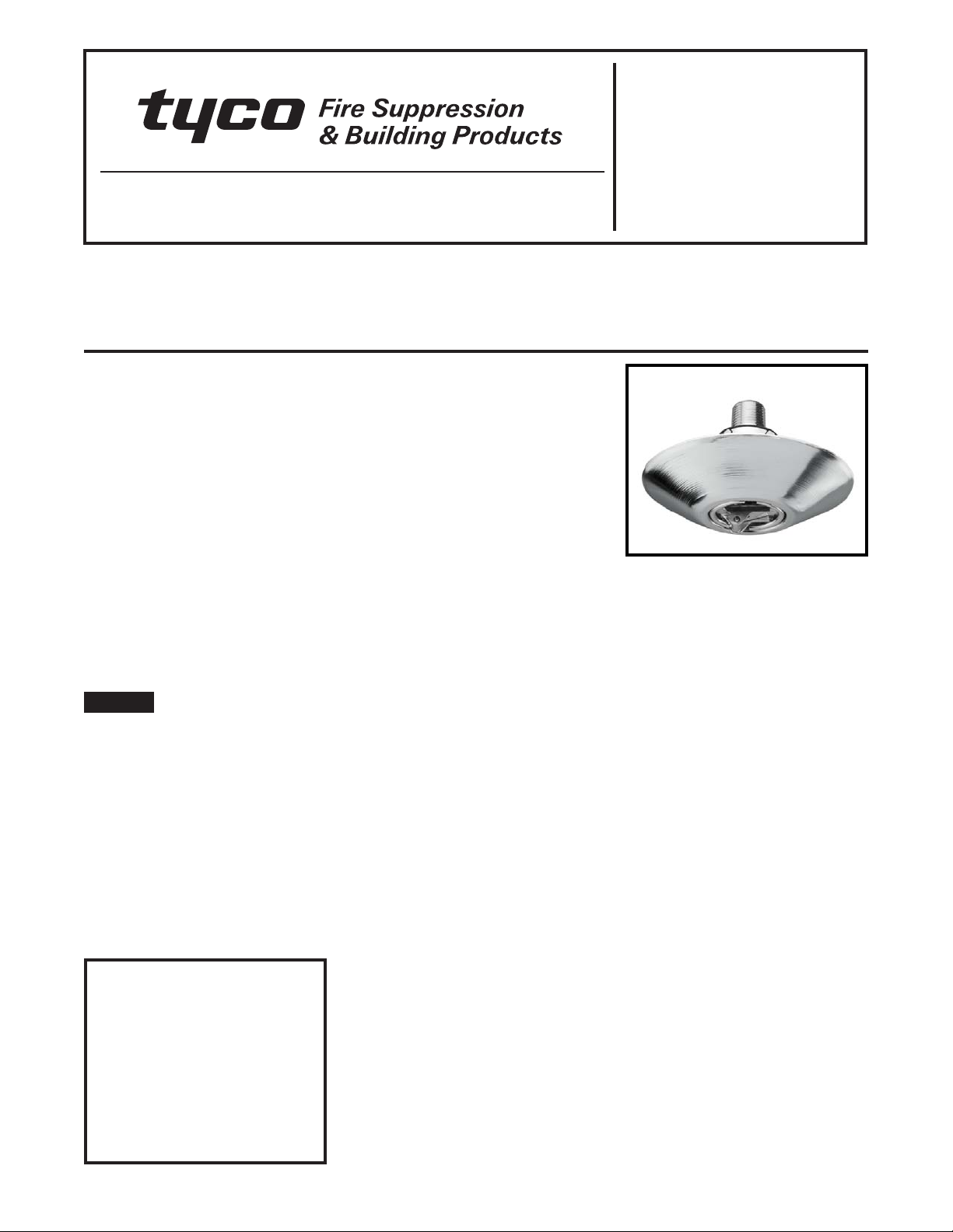
Model TFP PH2 — 5.6 K-factor
Institutional Pendent Sprinklers
Standard Response, Standard Coverage
General
Description
The Tyco® Model TFP PH2, 5.6
K-factor, Institutional Pendent Sprinklers are standard response standard
coverage, fusible solder type spray
sprinklers designed for use in areas
such as correctional, detention, and
mental health care facilities.
The unique features of the Model TFP
PH2 provide a tamper resistant sprinkler design that helps eliminate the
opportunity for individuals to injure
themselves or others with the components of a fire sprinkler. At the same
time, the Model TFP PH2 optimizes an
aesthetically appealing flush design
that conceals most of the operating
parts.
NOTICE
The Model TFP PH2 Institutional Pendent Sprinklers described herein must
be installed and maintained in compliance with this document, as well as
with the applicable standards of the
National Fire Protection Association, in
addition to the standards of any other
authorities having jurisdiction. Failure
to do so may impair the per formance
of these devices.
The owner is responsible for maintaining their fire protection system and
devices in proper operating condition.
The installing contractor or manufacturer should be contacted with any
questions.
IMPORTANT
Always refer to Technical Data
Sheet TFP700 for the “INSTALLER
WARNING” that provides cautions
with respect to handling and installation of sprinkler systems and components. Improper handling and
installation can permanently damage a sprinkler system or its components and cause the sprinkler to fail
to operate in a fire situation or cause
it to operate prematurely.
Sprinkler
Identification
Number (SIN)
TY3290
Technical
Data
Approvals
UL and C-UL Listed
NYC under MEA 351-01-E
(Refer to the Design Criteria section.)
Maximum Working Pressure
175 psi (12,1 bar)
Inlet Thread Connection
1/2 inch NPT
Discharge Coefficient
K=5.6 GPM/psi
Temperature Ratings
165°F/74°C or
212°F/100°C
Finishes
Sprinkler: Chrome Plated
Escutcheon: Chrome Plated
Physical Characteristics
Body ..................... Brass
Deflector................. Bronze
Deflector Reinforcement .... B r o n z e
Deflector Post............. Bronze
Deflector Post Pin ......... Bronze
Deflector Core ............ Bronze
Compression Screw........ Bronze
Lever.................... Bronze
Release Spring ............ Bronze
Core Sleeve ..............Copper
Sealing Assembly................
. . . . . . . . .Beryllium Nickel w/ Teflon†
Fusible Element .................
. . . . . Solder, Copper, Stainless Steel
Dust Cover .... Chrome Plated Steel
1/2
(80,6 LPM/bar
†
DuPont Registered Trademark
1/2
)
Operation
In the standby condition, the design
of the Model TFP PH2 is such that a
dynamic load of 80 lbs. (36 kg) or more
applied to the linkage mechanism will
release the sprinkler. Also, when properly installed, the escutcheon is held
fast to the ceiling to deter its removal.
The shape of the escutcheon cannot
be easily grasped, which further deters tampering.
A fusible solder operating element secures the linkage mechanism of the
Model TFP PH2. When the rated temperature is reached, the solder melts,
releasing the linkage mechanism that
holds the sprinkler closed. This allows
the deflector to extend downward and
water to flow.
Design
Criteria
The Tyc o® Model TFP PH2, 5.6
K-factor, Institutional Pendent Sprinklers (TY3290) are intended for use
with fire protection systems designed
in accordance with the standard installation rules recognized by the applicable Listing or Approval agency
(for example, Listing is based on NFPA
13 requirements).
Page 1 of 4 JULY 2009 TFP650
Page 2
TFP650
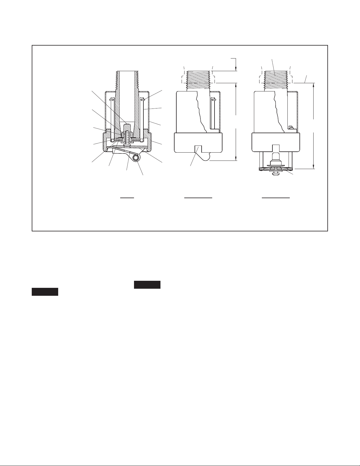
CROSS-SECTION
VIEW
INSTALLED
SIDE VIEW SIDE VIEW
OPERATED
Components:
1/2" NPT
SPRINKLER
WRENCHING
NOTCH (2)
DEFLECTOR
IN OPERATED
POSITION
SPRINKLER
FITTING
FACE OF
NOMINAL MAKE-IN
7/16" (11.1 mm)
(80.8 mm)
3.18"
2.81"
(71.4 mm)
13
12
9
1
4
5
10
8
2
3
11
7
6
-
2 Deflector
Screw
Deflector Core
Compression
Deflector Post
Deflector
-
8
-
4
7
-
3
-
Body1
-
Pin (2 Req'd)
Deflector Post
-
6
5
-
Reinforcement
(2 Req'd)
Dust Cover
Sealing Assembly
Fusible Element
Core Sleeve
Release Spring
Lever
9
-
10
-
11
-
12
-
13
-
Page 2 of 4
Only the Institutional Escutcheons
shown in Figure 2 can be utilized with
the Model TFP PH2. A maximum of
three Model 1752 Spacers only can be
utilized with Style B1 or C Institutional
Escutcheons when vertical adjustment
is desired.
NOTICE
The integrity of the tamper resistant
design of the Institutional Escutcheons
is dependent on the piping installation
d e si g n. W h en i n st a ll e d p ro p e r ly , th e I nstitutional Escutcheon is held fast to the
mounting surface by the tightening of
the sprinkler assembly into the sprinkler
fitting. In order to accomplish a proper
installation, the sprinkler fitting must be
p r o p e r l y l o c a t e d w i t h r e s p e c t t o t h e d i s tance from the face of the sprinkler fitting to the face of the mounting surface
(Ref. Fig. 2); the sprinkler fitting being
r i g i d l y s e c u r e d a n d h e l d i m m o b i l e ; a n d ,
the center-line of the sprinkler fitting
being perpendicular to the mounting
surface to assure that the escutcheon
sits squarely against the mounting
surface around the entire perimeter of
the Institutional Escutcheon.
fIguRe 1
MOdel TfP Ph2
INsTITuTIONAl PeNdeNT sPRINkleR
Installation
The Ty c o® Model TFP PH2, 5.6
K-f a ctor, Sprinklers must be installed
in accordance with the following
instructions.
NOTICE
Refer to the Design Criteria section for
important information regarding the
piping installation design and its effect
o n m ai nt ain in g t he int eg ri ty o f t he ta mper resistant design of the Institutional
Escutcheons.
Obtain a 1/2 inch NPT sprinkler joint
by applying a minimum to maximum
torque of 7 to 14 ft.lbs. (9,5 to 19,0
Nm). Higher levels of torque can distort the sprinkler Inlet with consequent
leakage or impairment of the sprinkler.
Do not attempt to compensate for improper location of the sprinkler fitting by
under- or over-tightening the sprinkler.
Re-adjust the position of the sprinkler
fitting to suit, or increase or decrease
the number of Model 1752 Spacers,
as applicable.
A f te r th e i n st a l la t i on i s c om p le t e, ma k e
certain that the Institutional Escutcheon
i s h e l d f a s t t o t h e m o u n t i n g s u r f a c e a n d
that it sits squarely against the ceiling
around its entire perimeter.
Step 1. Install the TFP PH2 Sprinklers
only in the pendent position and with
the center-line of the waterway perpendicular to the ceiling.
Step 2. With the Institutional Escutcheon in place and with pipe thread sealant applied to the pipe threads, hand
tighten the sprinkler into the sprinkler
fitting.
Step 3. Wrench-tighten the Sprinkler using only the Model 1509-3
Sprinkler Wrench (Ref. Fig. 4). Apply
the wrenching teeth of the Sprinkler
Wrench to the sprinkler wrenching
notch areas (Ref. Fig. 1).
Step 4. After the installation is complete, make certain that the Institutional Escutcheon is held fast to
the mounting surface and that it sits
squarely against the ceiling around its
entire perimeter.
Page 3

UP TO
#1752
THREE
SPACERS
1-3/16"
(30.2 mm)
1.11" (28.2 mm) MIN.
1.33" (33.8 mm) MAX.
1.70" (43.2 mm) MAX.
1.48" (37.6 mm) MIN.
WITH 3 SPACERS
WITH NO SPACERS
(127.0 mm)
5" DIA.
DIAMETER DETERMINED
BY CLEARANCE FOR
REDUCING COUPLING
(82.6 mm)
3-1/4" DIA.
(4.8 mm)
3/16"
(41.1 mm)
1.62"
(30.2 mm)
1.19"
DIAMETER DETERMINED
REDUCING COUPLING
BY CLEARANCE FOR
WITH 3 SPACERS
WITH NO SPACERS
DIAMETER DETERMINED
BY CLEARANCE FOR
REDUCING COUPLING
4-1/4" DIA.
(108.0 mm)
SPACERS
2-9/16"
UP TO
THREE
#1752
(65.1 mm)
2.81" (71.4 mm) MAX.
2.59" (65.8 mm) MIN.
FLUSH MIN.
0.22" (5.6 mm) MAX.
STYLE C
STYLE A
SPACERS
STYLE B1
WITH 3
(1)
(2)
(1)
(2)
(1)
(2)
(1)
(2)
(1)
(2)
(1)
(2)
TFP650
Page 3 of 4
Care and
Maintenance
The Tyc o® Model TFP PH2, 5.6
K-fa ctor Sprinklers must be maintained and serviced in accordance
with the following instructions.
NOTICE
Service inspections should be made
on a regular basis to detect possible
damage or alterations to the sprinkler
and escutcheon. Inspections should
include making certain that the Institutional Escutcheon is held fast to the
mounting surface. Damaged or altered
sprinklers are to be replaced immediately
to avoid personal injury and to prevent
use for causing personal injury, as well
as to maintain the sprinkler system in an
operative condition.
Before closing a fire protection system
main control valve for maintenance work
on the fire protection system that it controls, obtain permission to shut down
the affected fire protection systems
from the proper authorities and notify
all personnel who may be affected by
this action.
Replace sprinklers that are leaking or
exhibiting visible signs of corrosion.
Never paint, plate, coat, or otherwise
alter automatic sprinklers after they
leave the factory. Replace modified or
over-heated sprinklers.
Exercise care to avoid damage to the
sprinklers before, during, and after
installation. Replace sprinklers damaged by dropping, striking, wrench
twisting, wrench slipping, or the like.
Responsibility lies with the owner for
the inspection, testing, and maintenance of their fire protection system
and devices in compliance with this
document, as well as with the applicable standards of the National Fire
Protection Association (for example,
NFPA 25), in addition to the standards
of any other authorities having jurisdiction. Contact the installing contractor or sprinkler manufacturer regarding
any questions.
Automatic sprinkler systems should
be inspected, tested, and maintained
by a qualified Inspection Service in
accordance with local requirements
and/or national codes.
fIguRe 2
INsTITuTIONAl escuTcheON OPTIONs
fOR use wITh The MOdel TfP Ph2
Page 4

SHOULDER
PIPE PLUG
SPRINKLER
REDUCING
FITTING
CUP
RECESSED
CONCRETE
WOODEN
FORM
SYSTEM
PIPE
1"
SUPPORT
PIPE
MODEL 1754
MODEL 1290-8
MODEL 1753
1/2" DRIVE
ACCEPTS
TEETH
WRENCHING
TFP650
Page 4 of 4
INsTAllATION IN cONcReTe wITh sTyle A escuTcheON
fIguRe 3
Ordering
Procedure
Contact your local distributor for availability. When placing an order, indicate the full product name.
Sprinkler Assemblies
Specify: 5.6 K-factor, Chrome Plated, (temperature rating), Model TFP
PH2 (TY3290) Institutional Pendent
Sprinkler.
16 5F/ 74C ................ P/N 51-10 4-9 -165
212F/100C ............... P/ N 51-104-9-212
Separately Ordered Escutcheons
Specify: Style (A, B1, or C), Chrome
Plated, Institutional Escutcheons.
Style A ...................P /N 56- 012-7- 622
Style B1 .................P /N 5 6-0 01-7- 511
Style C ..................P /N 56 -001-7-513
Separately Ordered Wrenches
Specify: Model 1509-3 Sprinkler
Wrench, P/N 56-001-5-093.
Limited
Warranty
Products manufactured by Tyco Fire
Suppression & Building Products
(TFSBP) are war ranted solely to the
original Buyer for ten (10) years against
defects in mate rial and workmanship
when paid for and properly installed
and maintained under normal use and
service. This warranty will expire ten
(10) years from date of shipment by
TFSBP. No warranty is given for products or com ponents manufactured by
companies not affiliated by ownership
with TFSBP or for products and components which have been subject to
misuse, improper installation, corrosion, or which have not been installed,
maintained, modi fied or repaired in accordance with ap plicable Standards of
the National Fire Protection Association, and/or the standards of any other
Authorities Having Jurisdiction. Materials found by TFSBP to be defective
shall be either repaired or replaced, at
TFSBP’s sole option. TFSBP neither
assumes, nor authorizes any person
to assume for it, any other obligation
in connection with the sale of products
or parts of prod ucts. TFSBP shall not
be responsible for sprinkler system
design errors or inac curate or incomplete information sup plied by Buyer or
Buyer’s repre sentatives.
In no event shall TFSBP be liable, in
contract, tort, strict liability or under
any other legal theory, for incidental, indirect, special or consequential
dam ages, including but not limited to
labor charges, regardless of whether TFSBP was informed about the
fIguRe 4
MOdel 1509-3
sPRINkleR wReNch
possibility of such damages, and in no
event shall TFSBP’s liability exceed an
amount equal to the sales price.
The foregoing warranty is made in
lieu of any and all other warranties,
express or implied, including warranties of merchantability and fitness for
a particular purpose.
This limited warranty sets forth the exclusive remedy for claims based on
failure of or defect in products, materials or components, whether the claim
is made in contract, tort, strict liability
or any other legal theory.
This warranty will apply to the full extent permitted by law. The invalidity,
in whole or part, of any portion of this
warranty will not affect the remainder.
Separately Ordered Spacers for
Vertical Adjustment
Specify: Model 1752 Spacers for use
with Style B-1 and C Institutional Escutcheons, P/N 56-000-1-752.
Separately Ordered Parts for
Installation in Concrete With
Type A Escutcheon
(Refer to Figure 3.)
Specify: Model 1753 Recessed
Cup for use with Style A Escutcheon for installation in concrete,
P/N 56-000-1-753.
Specify: Model 1290-8 Pipe Plug With
Shoulder for use with Style A Escutcheon for installation in concrete,
P/N 56-001-2-908.
Specify: Model 1754 Pipe Support for
use with Style A Escutcheon for installation in concrete, P/N 56-000-1-754.
© 200 9 TYCO FIRE SUPPRESSION & BUILDING PRODUCTS
, 451 North Cannon Avenue, Lansdale, Pennsylvania 19446
 Loading...