

Page 1

Illustra Essentials
Indoor / Outdoor HD Bullet
Quick Start Guide
8200-1102-01 B0
Page 2

i
Notice
Please read this manual thoroughly and save it for future use before attempting to connect or operate this unit.
The information in this manual was current when published. The manufacturer reserves the right to revise and
improve its products. All specifications are therefore subject to change without notice.
Copyright
Under copyright laws, the contents of this manual may not be copied, photocopied, reproduced, translated or
reduced to any electronic medium or machine-readable form, in whole or in part, without prior written consent of
Tyco Security Products. © 2014 Tyco Security Products. All rights reserved.
Customer Service
Thank you for using Tyco Security Products. We support our products through an extensive worldwide network
of dealers. The dealer through whom you originally purchased this product is your point of contact if you need
service or support. Our dealers are empowered to provide the very best in customer service and support.
Dealers should contact Tyco Security Products at (800) 507-6268 or (561) 912-6259 or on the Web at
www.illustraessentials.com.
Trademarks
The trademarks, logos, and service marks displayed on this document are registered in the United States [or
other countries]. Any misuse of the trademarks is strictly prohibited and Tyco Security Products. will
aggressively enforce its intellectual property rights to the fullest extent of the law, including pursuit of criminal
prosecution wherever necessary. All trademarks not owned by Tyco Security Products. are the property of their
respective owners, and are used with permission or allowed under applicable laws.
Product offerings and specifications are subject to change without notice. Actual products may vary from
photos. Not all products include all features. Availability varies by region; contact your sales representative.
Page 3

ii
Important Safeguards and Warnings
1.Electrical safety
All installation and operation should conform to your local electrical safety codes.
The power shall conform to the requirement in the SELV (Safety Extra Low Voltage) and the Limited
power source is rated 12V DC or 24V AC in the IEC60950-1. (Refer to general introduction)
Please note: Do not connect two power supplying sources to the device at the same time; it may result in
device damage! The product must be grounded to reduce the risk of electronic shock.
We assume no liability or responsibility for all the fires or electrical shock caused by improper handling or
installation.
We are not liable for any problems caused by unauthorized modification or attempted repair.
2.Transportation security
Heavy stress, violent vibration or water splash are not allowed during transportation, storage and
installation.
3.Installation
Do not apply power to the camera before completing installation.
Please install the proper power cut-off device during the installation connection.
Always follow the instruction guide the manufacturer recommended.
4.Qualified engineers needed
All the examination and repair work should be done by the qualified service engineers.
We are not liable for any problems caused by unauthorized modifications or attempted repair.
5.Environment
This series network camera should be installed in a cool, dry place away from direct sunlight,
inflammable, explosive substances and etc.
Please keep it away from the electromagnetic radiation object and environment.
Please make sure the CCD (CMOS) component is out of the radiation of the laser beam device.
Otherwise it may result in CCD (CMOS) optical component damage.
Please keep the sound ventilation.
Do not allow the water and other liquid falling into the camera.
Thunder-proof device is recommended to be adopted to better prevent thunder.
The grounding studs of the product are recommended to be grounded to further enhance the reliability of
the camera.
Page 4
iii
6. Daily Maintenance
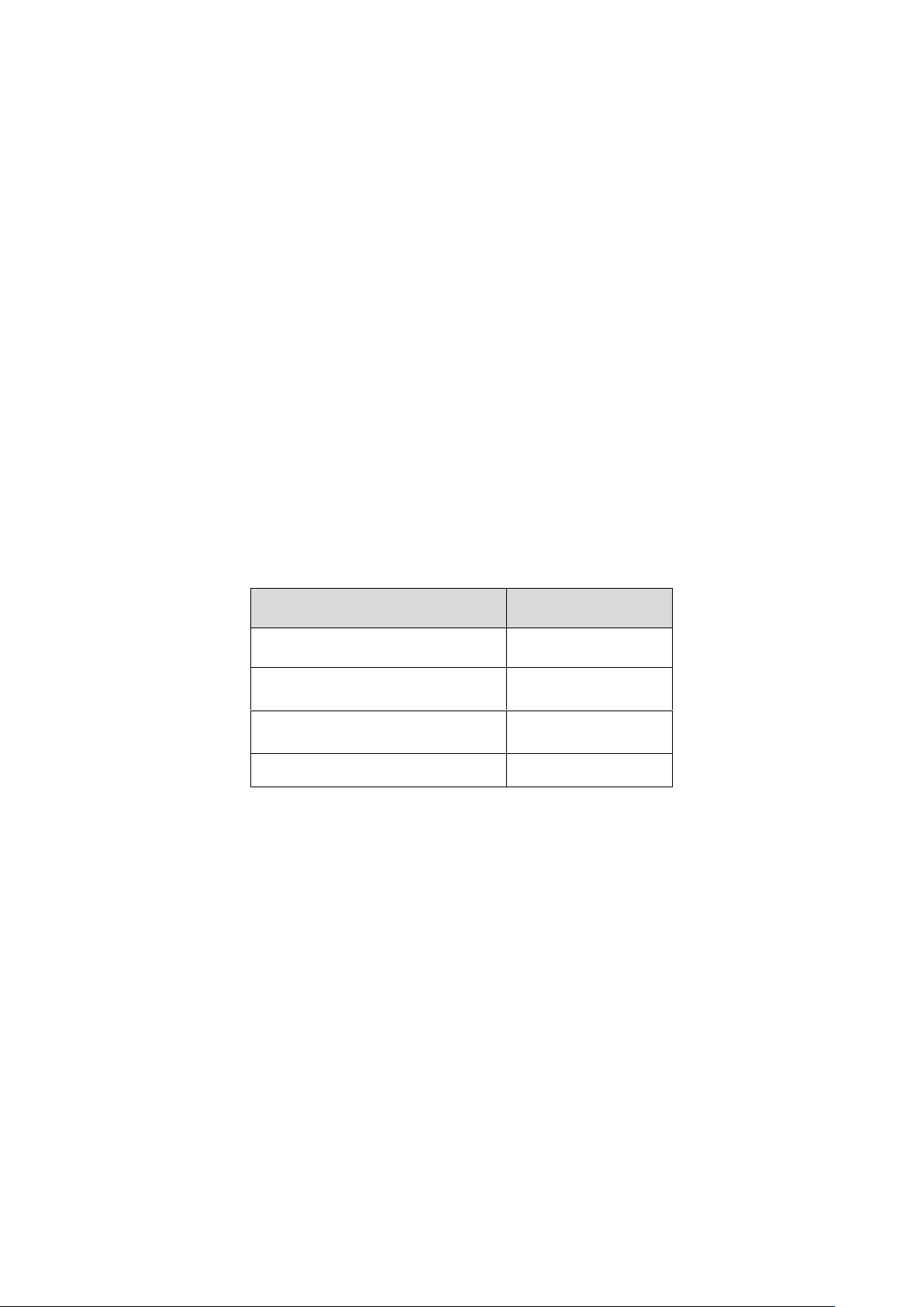
Accessory Name
Amount
Network Camera Unit
1
Quick Start Guide
1
Installation Accessories Bag
1
CD
1
Please shut down the device and then unplug the power cable before you begin daily maintenance work.
Do not touch the CCD (CMOS) optic component. You can use the blower to clean the dust on the lens
surface.
Always use the dry soft cloth to clean the device. If there is too much dust, please use the water to dilute
the mild detergent first and then use it to clean the device. Finally use the dry cloth to clean the device.
Please put the dustproof cap to protect the CCD (CMOS) component when you do not use the camera.
Dome enclosure is the optical component, do not touch the enclosure when you are installing the device
or clean the enclosure when you are doing maintenance work. Please use professional optical clean
method to clean the enclosure. Improper enclosure clean method (such as use cloth) may result in poor
IR effect of camera with IR function.
7. Accessories
Be sure to use all the accessories recommended by manufacturer.
Before installation, please open the package and check all the components are included.
Contact your local retailer ASAP if something is broken in your package.
Page 5

iv
Table of Contents
Important Safeguards and Warnings .................................................................................................................. ii
Table of Contents .............................................................................................................................................. iv
Framework ......................................................................................................................................................... 1
Cable ......................................................................................................................................................... 1
Framework and Dimension ....................................................................................................................... 2
Device Installation .............................................................................................................................................. 4
Quick Configuration Tool ................................................................................................................................... 6
Overview ................................................................................................................................................... 6
Operation .................................................................................................................................................. 6
Web Operation ................................................................................................................................................... 8
Network Connection .................................................................................................................................. 8
Login and Main Interface .......................................................................................................................... 8
Appendix Toxic or Hazardous Materials or Elements .................................................................................... 10
Page 6

1
No.
Port
Name
Function
Connection
Note
1
LAN
Network port
Ethernet
port
Connect to standard Ethernet cable.
Note: Some devices do not support PoE.
Before making crystal head, pull the anti-dust, waterproof
cover through network cable.
2
DC 12V
Power input
port
/
Power port. Input DC 12V.
Cable
You can refer to the following figure for cable information. See Figure 1-1
Framework
Figure 1-1 Cable
Please refer to the following sheet for detailed information.
Page 7

2
Framework and Dimension
Please refer to the following figures for dimension information. The unit is mm. See Figure 1-2 to
Figure 1-4
Figure 1-2
Page 8

3
Figure 1-3
Figure 1-4
Page 9

4
Device Installation
Note
Before the installation, please make sure the installation environments can at least support 3x weight
of the camera.
Figure 2-1 Device installation 1
Please see Figure 2-1 and Figure 2-2.
Step 1
Stick installation sticker to designated surface where you will install the device (wall or ceiling).
Step 2
Dig a hole according to position of hole on installation sticker.
Step 3
Open accessories bag, take out expansion bolt and insert it into the hole you just dug.
Step 4
Open accessories bag, take out screw. Tighten the 4 screws to fix the device on the installation
surface (wall or ceiling). You can move device sunshade back and forth. When you have fixed the
device, you must tighten screws on sunshade.
Step 5
Plug external wiring of the device properly.
Page 10

5
Figure 2-2 Device installation 2
Step 6
Use Philip’s head screw (in accessories bag) to loosen adjusting screw.
Step 7
Adjust the device in all possible directions, and set its monitoring direction.
Step 8
Use Philip’s head screw to tighten the screws.
Page 11

6
Quick Configuration Tool
Overview
Quick configuration tool can search current IP address, modify IP address. At the same time, you can
use it to upgrade the device.
Please note the tool only applies to the IP addresses in the same segment.
Operation
Double click the “ConfigTools.exe” icon, you can see an interface is shown as in Figure 3-1.
In the device list interface, you can view device IP address, port number, subnet mask, default
gateway, MAC address and etc.
Figure 3-1 Search interface
Select one IP address and then right click mouse, you can see an interface is shown as in Figure 3-2.
Select the “Open Device Web” item; you can go to the corresponding web login interface.
Page 12

7
Figure 3-2 Search interface 2
If you want to modify the device IP address without logging in the device web interface, you can
go to the configuration tool main interface to set.
In the configuration tool search interface (Figure 3-1), please select a device IP address and then
double click it to open the login interface. Or you can select an IP address and then click the
Login button to go to the login interface. See Figure 3-3.
In Figure 3-3, you can view device IP address, user name, password and port. Please modify the
corresponding information to login.
Please note the port information here shall be identical with the port value you set in TCP port in
Web Network interface. Otherwise, you cannot login the device.
If you are using device background upgrade port 3800 to login, other setups are all invalid.
Figure 3-3 Login prompt
After you logged in, the configuration tool main interface is shown as below. See Figure 3-4.
Figure 3-4 Main interface
Page 13

8
Input your IP
address here
Web Operation
This series network camera products support the Web access and management via PC.
Web includes several modules: Monitor channel preview, system configuration, alarm and etc.
Network Connection
Please follow the steps listed below for network connection.
Make sure the network camera has connected to the network properly.
DHCP is enabled by default.
Please set the IP address, subnet mask and gateway of the PC and the network camera
respectively. Network camera default IP address is 192.168.1.168. Subnet mask is
255.255.255.0. Gateway is 0.0.0.0
Use order ping ***.***.***.***(* network camera address) to check connection is OK or not.
Login and Main Interface
Open IE and input network camera address in the address bar. See Figure 4- 1.
Figure 4- 1
The login interface is shown as below. See Figure 4- 2.
Please input your user name and password.
Default factory name is admin and password is admin.
Note
For security reasons, please modify your password after you first login.
Page 14

9
Figure 4- 2
After you successfully logged in, please install WEB plug-in unit. Please refer to the Web Operation
Manual included in the resource CD for detailed operation instruction.
See Figure 4- 3.
Figure 4- 3
Page 15

10
Component Name
Toxic or Hazardous Materials or Elements
Pb
Hg
Cd
Cr VI
PBB
PBDE
Circuit Board Component
○ ○ ○ ○ ○
○
Device Construction Material
○ ○ ○ ○ ○
○
Wire and Cable
○ ○ ○ ○ ○
○
Packing Components
○ ○ ○ ○ ○ ○ Accessories
○ ○ ○ ○ ○
○
Appendix
Toxic or Hazardous Materials or Elements
O: Indicates that the concentration of the hazardous substance in all homogeneous materials in the
parts is below the relevant threshold of the SJ/T11363-2006 standard.
X: Indicates that the concentration of the hazardous substance of at least one of all homogeneous
materials in the parts is above the relevant threshold of the SJ/T11363-2006 standard. During the
environmental-friendly use period (EFUP) period, the toxic or hazardous substance or elements
contained in products will not leak or mutate so that the use of these (substances or elements) will not
result in any severe environmental pollution, any bodily injury or damage to any assets. The
consumer is not authorized to process such kind of substances or elements, please return to the
corresponding local authorities to process according to your local government statutes.
Note
1. This user’s manual is for reference only. Slight difference may be found in user interface.
2. All the designs and software here are subject to change without prior written notice.
3. All trademarks and registered trademarks mentioned are the properties of their respective
owners.
4. If there is any uncertainty or controversy, please refer to the final explanation of us.
5. Please visit our website for more information.
 Loading...