

Page 1
HS2TCHPRO/HS2TCHPROBLK Touchscreen User Manual
Uživatelská příručka dotykové obrazovky
HS2TCHPRO/HS2TCHPROBLK
HS2TCHPRO/HS2TCHPROBLK Touchscreen
Benutzerhandbuch
WARNING: This manual contains information on limitations regarding product use, function and information
on the limitation as to liability of the manufacturer. The entire manual should be carefully read.
UPOZORNĚNÍ: Tento návod obsahuje informace o omezení ve využívání výrobku a jeho funkci, a také informace
o omezení odpovědnosti výrobce. Celý návod si pečlivě přečtěte.
WARNUNG: Dieses Handbuch enthält Informationen hinsichtlich der Einschränkungen bei der Verwendung des
Produkts und der Funktionen und Informationen zu den Einschränkungen bezüglich der Haftung des Her-stellers.
Lesen Sie das gesamte Handbuch aufmerksam durch.
Page 2

Table of Contents
Table of Contents 2
Safety Notes 5
Important Safety Instructions 5
Regular Maintenance and Troubleshooting 5
Handling Precautions 5
Cleaning 5
Troubleshooting 5
Introduction 6
General System Operation 6
About Your Security System 6
Carbon Monoxide Detection (must be enabled by your Installer) 7
Fire Detection (must be enabled by your Installer) 7
Testing 7
Monitoring 7
Maintenance 7
Important Notice 7
Specifications and Features 8
Welcome Screen 8
Emergency Keys 9
Arming and Disarming the System 10
Stay Arm (Arming the Perimeter) 10
Silent Exi t Delay 10
Disarm 11
Away Arm 11
Exit Delay Time Restart 11
Alarm Cancel Window 11
Bell/Siren Sounds After Away Arming 12
Audible Exit Fault 12
Arming Error 12
Remote Arming and Di sarming 12
Using Your System 12
When Alarm Sounds 12
Intrusion (Burglary) Alarm Continuous Siren 12
If the Intrusion Alarm was Accidental 13
Fire Alarm Pulsed Siren 13
Wireless Carbon Monoxi de Alarm 13
Troubles 14
Alarm Memory 14
Sensor Reset 15
Outputs 15
Page 3

Additional Functions 16
Photos 16
Quick Exit 16
Time & Date Programming 16
Keypad Mode 16
Door Chime (Chime enable/disable) 16
Zone Bypass 16
Zone Status Indicators 17
Bypassed Zones 17
Bypassing Zones with a HS2TCHPRO/HS2TCHPROBLK 17
Options Menu 17
Access Codes 18
Assign Proximity Tags 18
Delete Proximity Tags 18
User Code Attributes 19
Inherent Attributes (all codes except installer and maintenance) 19
Programmable Attributes 19
Bell Squawk Attribute 19
Partition Assignment 19
Erasing an Access Code 19
Installer Menu 19
User Functions 20
Time and Date 20
Auto-Arm Time 20
Enable DLS/Allow System Service 20
Event Buffer 20
System Test 20
Auto-Arm/Disarm Control 21
User Call-up 21
Engineer's Reset 21
Keypad Configuration 21
Chime Enabled/Disabled 22
Arming 22
Partition Status 22
Keypad Mode 23
Managing Partitions 23
Partitions 23
Single Partition Operation 23
Loaning a Keypad to Another Partition 23
Global Keypad Operation 24
Fire and CO Zone Types 25
Page 4

Testing Your System 26
Testing Your Keypad Sounder and Siren 26
Testing Your Entire System 26
Walk Test Mode 26
Allowing Computer Access To Your System 26
Reference Sheets 27
System Information Enabled? 27
For Service 27
Central Station Information: 27
Installer Information: 27
Battery Installation / Service Date: 27
Access Codes (copy as needed) 28
Sensor / Zone Information (copy as needed) 29
Guidelines for Locating Smoke Detectors and CO Detectors 30
Smoke Detectors 30
Carbon Monoxide Detectors 31
Household Fire Safety Audit 32
Fire Escape Planning 32
License Agreement 33
Page 5

Safety Notes
Safety Notes
This manual shall be used in conjuncti on with t he PowerSeries Pro User manual for the compatible alarm control
panel: HS3032, HS3128, HS3248.
Always ensure you obtain the latest version of the User Guide. Updated versions of this User Guide are available
by contacting your distributor.
Warning: Read and save these instructions! Follow all warnings and instructions specified within this document
and/or on the equipment.
Important Safety Instructions
To reduce the risk of fire, electric shock and/or injury, observe the following:
l Do not spill any type of li quid on the equipment.
l Do not attempt to service this product yourself. Opening or removing the cover may expose you to dan-
gerous voltage or other risk. Refer servicing to qualified service personnel. Never open the device yourself.
l Do not touch the equipment and its connected cables during an electrical storm; there may be a risk of
electric shock.
l Do not use the Alarm System to report a gas leak if the system is near a leak.
Regular Maintenance and Troubleshooting
Keep your HS2TCHPRO/HS2TCHPROBLK Touchscreen keypad in optimal condition by following all the instructions that are included within this manual and/or marked on the product.
Handling Precautions
Do not apply excessive force to the display surface or the adjoining areas since this may cause the color tone to
vary.
Cleaning
l If the display surface is contaminated, breathe on the surface and gently wipe it with a soft, dry cloth. If
still not completely clean, moisten cloth with isopropyl alcohol.
l Do not use abrasives, water, thinners, solvents or aerosol cleaners (spray polish), any aromatic solvents,
ketones etc. that may enter through holes in the HS2TCHPRO/HS2TCHPROBLK Touchscreen keypad
and cause damage.
Troubleshooting
Occasionally, you may have a problem with your system. If this happens, your Alarm Controller will display an
error message. Refer to the provided list when you see an error message on the display. If additional help is
required, contact your distributor for service.
Warning: This equipment, HS2TCHPRO/HS2TCHPROBLK Touchscreen keypad shall be installed and used
within an environment that provides the poll ution degree max 2 and over-voltages category II non-hazardous locations, indoor only. It is designed to be installed, serviced and/or repaired by service persons only [service person
is defined as a person having the appropriate technical training and experience necessary to be aware of hazards to
which that person may be exposed in performing a task and of measures to minimize the risks to that person or
other persons]. There are no parts replaceable by the end-user within this equipment.
Warning: Never obstruct the access to the Alarm controller to which this equipment is connected. These safety
instructions should not prevent you from contacting the distributor and/or the manufacturer to obtain any further
clarification and/or answers to your concerns.
- 5 -
Page 6
Introduction
Introduction
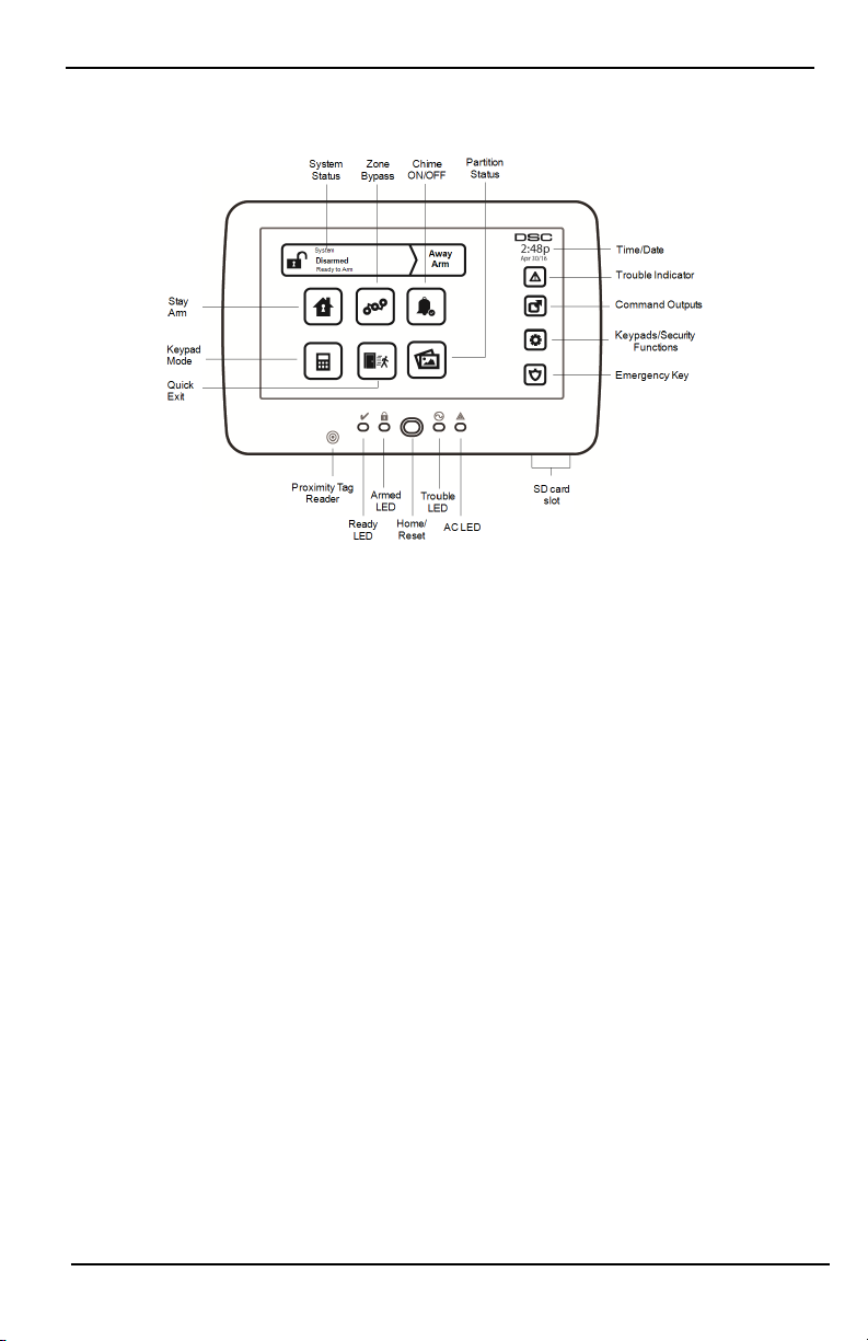
Figure 1- Controls and Indicators
The HS2TCHPRO/HS2TCHPROBLK Touchscreen is an interactive touch-sensitive color LCD that can be used on
any PowerSeries Pro control panel. Due to the custom requirements of individual installations, some of the features described here may perform differentl y than described. Refer to your Install er's Instructions for the details of
your specific installation and to the User Manual for general security system information.
General System Operation
Your security system is made up of a DSC control panel, one or more keypads and various sensors and detectors.
The control panel will be mounted out of the way in a utility closet or in a basement. The metal cabinet contains
the system electronics, fuses and standby battery.
Note: Only the i nstaller or service professional shall have access to the control panel.
All the keypads have an audible indicator and command entry keys. The keypad is used to send commands to the
system and to display the current system status. The keypad(s) will be mounted in a convenient locati on inside
the protected premises close t o the entry/exit door(s).
The security system has several zones of protection, each connected to one or more sensors (motion detectors,
glassbreak detectors, door contacts, etc.). "Alarm Memory" on page14 for information on sensors in alarm for this
Touchscreen keypad.
About Your Security System
Your DSC Security System has been designed to provide you with the greatest possible flexibility and convenience. Read this manual carefully and have your install er instruct you on your system's operation and on which
features have been impl emented in your system. All users of this system should be equally instructed in its use.
Fill out the “System Information” page with all of your zone information and access codes and store this manual
in a safe place for future reference.
Note: The PowerSeries security syst em includes specific false alarm reduction features and is classified in accordance with ANSI/SIA CP-01-2010 Control Panel Standard - Features for False Alarm Reduction. Please consult your
installer for further information regarding the false alarm reduction features built into your system as all are not
covered in this manual.
- 6 -
Page 7

Introduction
Carbon Monoxide Detection (must be enabled by your Installer)
This equipment is capable of monitoring carbon monoxide detectors and providi ng a warning if carbon monoxide
is detected. Please read the Family Escape Planning guidelines in this manual and instructions that are available
with the carbon monoxide detector.
Fire Detection (must be enabled by your Installer)
This equipment is capable of monitoring fire detection devices such as smoke detectors and providing a warning
if a fire condition is detected. Good fire detection depends on having adequate number of detectors placed in
appropriate locations. This equipment should be installed in accordance with NFPA 72 (N.F.P.A., Batterymarch
Park, Quincey MA 02269). Carefully review the Family Escape Planning guidelines in this manual.
Testing
To ensure that your system continues to function as intended, you must test it weekly. Please refer to the “Testing
your System” section in this manual. If your system does not function properly, call your installing company for
service.
Monitoring
This system is capable of transmitting alarms, troubles and emergency information to a central station. If you initiate an alarm by mistake, immediately call the central station to prevent an unnecessary response.
Note: The monitoring function must be enabled by the installer before it becomes functional.
Note: There is a communicator delay of 30 seconds in this control panel. It can be removed, or it can be increased
up to 45 seconds, at the option of the end-user by consulting with the installer.
Note: For CP-01 systems, the monitoring function must be enabled by the inst aller before it becomes functional.
Maintenance
With normal use, the system requires minimum maintenance. Note the following points:
l Use the system test described in “Testing Your System” to check the battery condition. We recommend,
however that the standby batteries be replaced every 3 - 5 years.
l For other system devices such as smoke detectors, passive infrared, ultrasonic or microwave motion
detectors, or glassbreak detectors, consult the manufacturer's literature for testing and maintenance
instructions.
Important Notice
A security system cannot prevent emergencies. It i s only int ended to alert you and, if included, your central station of an emergency situation. Security systems are very reliable but they may not work under all conditions, and
they are not a substitute for prudent security practices or life and property insurance. Your security system should
be installed and serviced by qualified security professionals who should instruct you on the level of protection
that has been provided and on system operations.
- 7 -
Page 8

Specifications and Features
Specifications and Features
Display 7" TFT (800 x 480) pixel) Color Touchscreen
Home button Home/Calibration/Reset
LED indicators 4 (Ready, Armed, Trouble, AC)
Dimensions (mounting) 8.5" x 5.1" x 0.8" [127.9 mm (L) x 195 mm (W) x 20.35 mm (D)]
Horizontal viewing angle 70°
Vertical viewing angle 70° (top), 50° (bottom)
Brightness 280 cd/m²
Operating environment
SD card slot Holds any standard Secure Digital (SD) card* (32 x 24 x 2.1 mm)
*If necessary, the SD card can be formatted to file system FAT16 or 32 using a PC. The maximum size SD card
supported is 32GB.
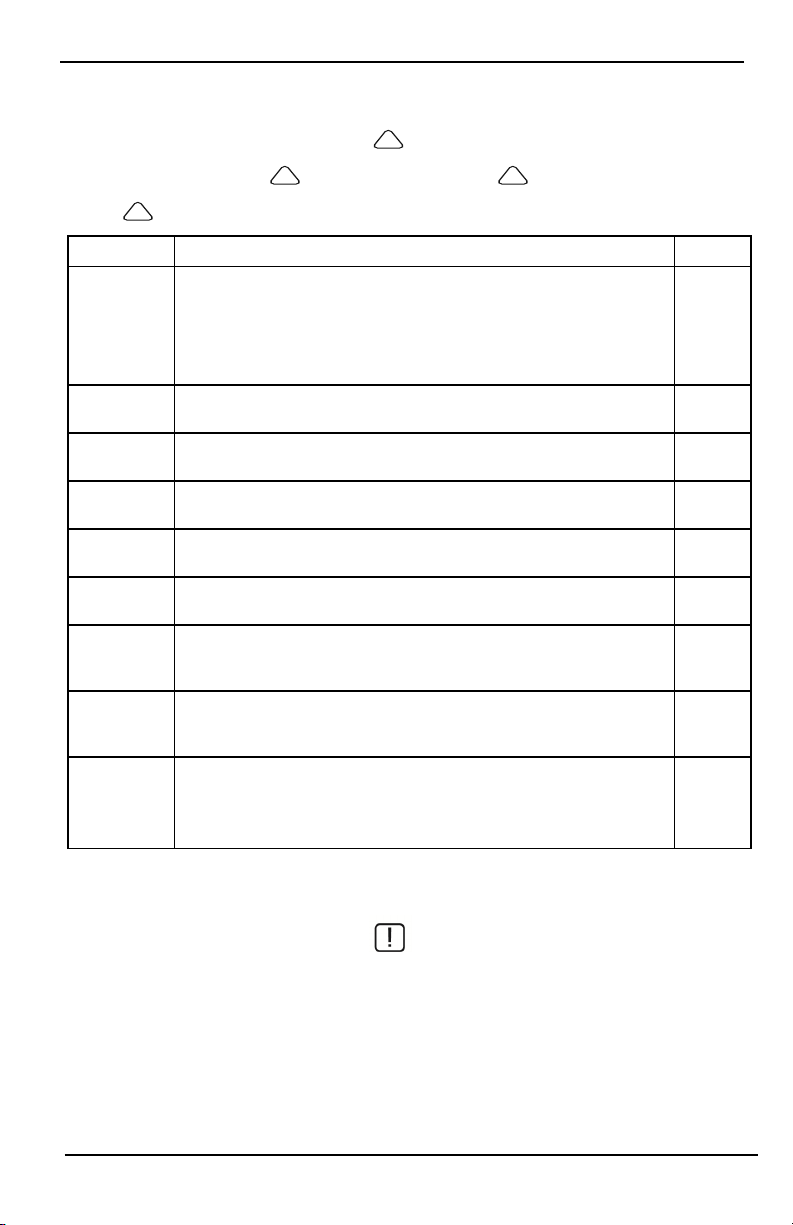
Welcome Screen
The date and time are displayed in the upper right corner of the screen. The system status (i.e., Ready, Armed, Exit
Delay etc.) is displayed at the top of the screen.
Figure 2- Welcome Screen
0°C to +49°C (32°F to 120°F)
93% (max) relative humidity non-condensing
- 8 -
Page 9
Emergency Keys
Emergency Keys
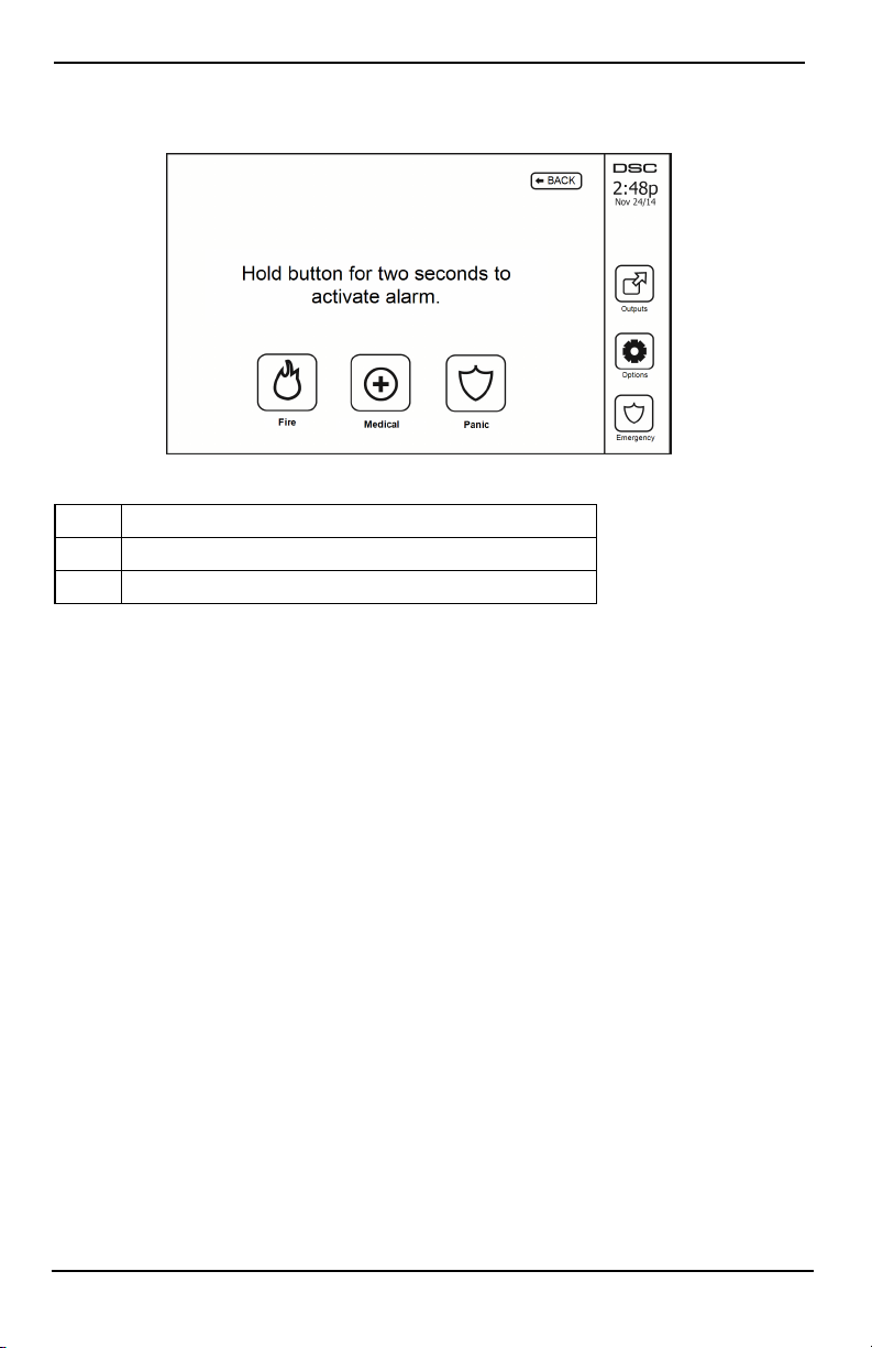
Figure 3- Emergency Screen
When the emergency key is pressed, a new screen is displayed with:
Fire Fire Assistance Required. Press and hold for 2 seconds to activate.
Medical Medical Assistance Required. Press and hold for 2 seconds to activate.
Panic Police Assistance Required. Press and hold for 2 seconds to activate.
Important: The Medical and Panic keys are ON by default. The Fire key will not function unless programmed by
the Install er. Please ask your installer if the Fire, Medical and Panic keys are enabled.
Note: These events are recorded in the log.
- 9 -
Page 10
Arming and Disarming the System
Arming and Disarming the System
Stay Arm (Arming the Perimeter)
Ask your alarm company if this function is available on your system.
Stay arming bypasses the interior protection (i.e., motion sensors) and arms the perimeter of t he system (i.e., doors
and windows). Close all sensors (i.e., stop motion and close doors). The Ready ( ) indicator should be on. Press
the Stay Arm button and/or enter your Access Code and do not leave the premises (if your installer has pro-
grammed this button). During exit delay, the Armed ( ) and Ready ( )indicators turn on to visually i ndicate
that the system is arming.
When the exit delay expires, the Ready LED turns off, the Armed LED remains on and the keypad stops sounding
to indicate that the alarm system is armed.
Note: For SIA FAR listed panels, the Stay Arming exit delay will be twice as long as the Away Arming exit
delay.
Silent Exit Delay
If the system is armed using the Stay Arm button or using t he "No Entry" Arming method ([*][9][access code], the
audible progress annunciati on (keypad buzzer) is silenced and the exit time doubled for that exit period only (CP01 versions only).
Note: For non CP-01 versions, Standard exit time is used.
When Stay Arm is selected from the Home screen:
l The display indicates “Exit Delay in Progress,” and the pre-programmed exit delay begins.
l The Armed LED Indicator turns on.
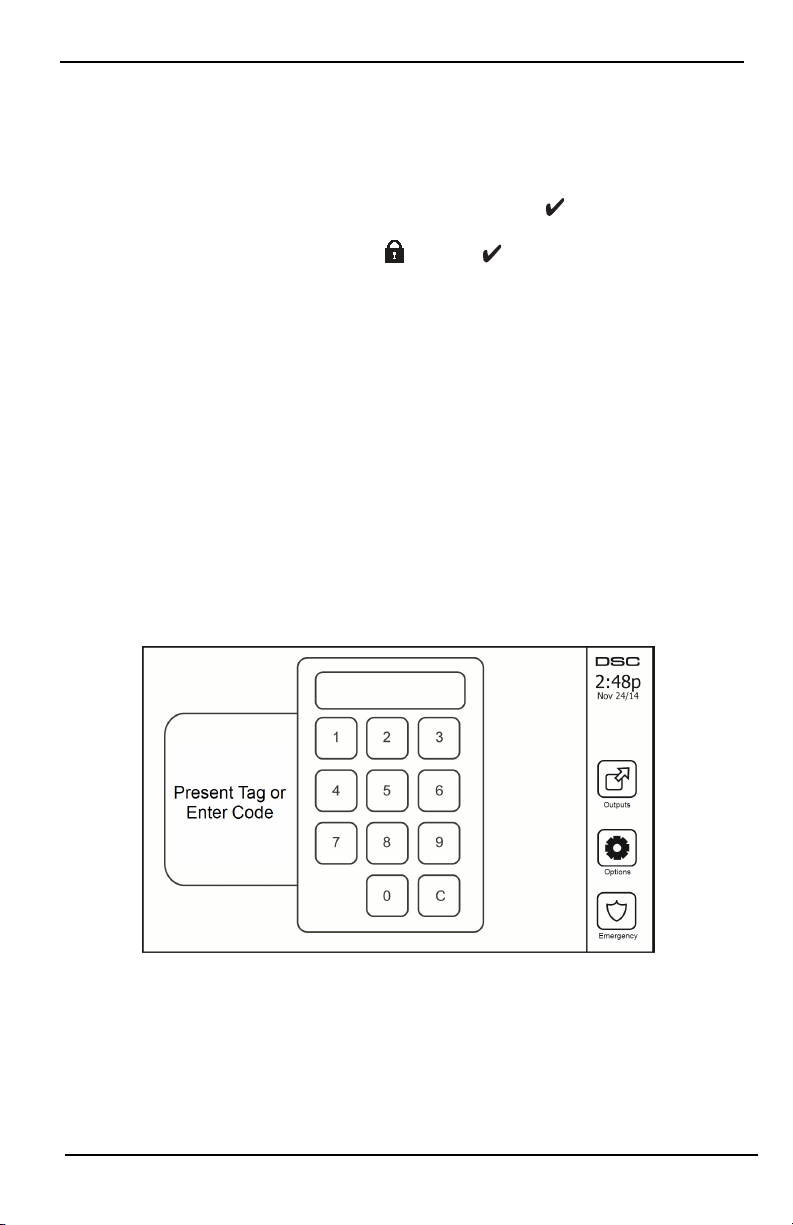
If Quick Arm is not enabled by the installer, then a numerical keypad is displayed (see following figure). Enter a
valid access code to proceed.
Figure 4- Keypad
If Disarm is selected during the exit delay, a numeric keypad is displayed.
l Enter (tap) your access code.
l The arming sequence is aborted and the system returns to the Home screen.
l The Armed LED turns OFF.
At the end of the pre-programmed exit delay:
- 10 -
Page 11

Arming and Disarming the System
l The Disarm screen is displayed.
l The Ready Indicator turns OFF.
l “Stay Armed-Bypass” is displayed in the Status Bar.
Note: This screen will go into stand-by mode after 15 minutes. Tap the screen to restore the display.
Disarm
If Disarm is selected:
l A numerical keypad is displayed.
l Enter your Access Code in the keypad.
l The system returns to the Home screen and the red Armed indicator turns OFF.
l The alarm status is momentarily displayed in t he status bar, then "Ready" is displayed.
l The green Ready indicator turns ON.
Note: If your code is invalid, the system will not disarm and a 2-second error tone will sound. If this happens,
press # and try again.
Away Arm
When Away Arm is selected:
l Enter a valid access code to proceed.
l The Armed LED Indicator turns ON.
l "Exit Delay in Progress" is displayed in the Status Bar. The pre-programmed exit delay begins.
l The touchscreen "beeps" at a 1-second urgency interval during the exit delay. Then 3 beeps sound in the
last 10 seconds.
Note: If Quick Arm is not enabled by t he installer, a numerical keypad is displayed.
If Disarm is selected during the exit delay:
l A numeric keypad i s displayed. Tap your access code.
l The Arming sequence is aborted and the system returns to the Home screen.
l The Armed LED turns OFF.
At the end of the pre-programmed exit delay:
l The Disarm screen is displayed.
l The Ready Indicator turns OFF.
l "Away Armed" is displayed in the Status Bar.
Exit Delay Time Restart
The control panel provides an option where if an entry/exit zone is tripped, a second time prior to the end of the
exit delay, the exit delay time restarts. The exit delay timer can only be restarted once.
Alarm Cancel Window
The control panel provides a period of time in which the user can cancel the alarm transmission. The minimum duration of this time is five minutes. If the programmed alarm transmission delay has expired, canceling an alarm
sends a message to the monitoring station. Upon a successful transmission of the cancelation message, the keypad
will beep 6 times.
- 11 -
Page 12

Arming and Disarming the System
Bell/Siren Sounds After Away Arming
Audible Exit Fault
In an attempt to reduce false alarms, the Audible Exit Fault is designed to notify you of an improper exit when
arming t he system in the Away mode. In the event that you fail to exit the premises during the allotted exit delay
period, or if you do not securely close the Exit/Entry door, the system wil l noti fy you that it was improperly
armed in two ways: the keypad will emit one continuous beep and the bell or siren will sound.
Your installer will tell you if this feature has been enabled on your system. If this occurs:
1. Re-enter the premises.
2. Enter your access code to disarm the system. You must do this before the entry delay timer expires.
3. Follow the Away arming procedure again, making sure to close the entry/exit door properly.
Arming Error
An error tone will sound if the system is unable to arm. This will happen if the system is not ready to arm (i.e.,
sensors are open), or if an incorrect user code has been entered. If this happens, ensure all sensors are secure. Press
[#] and try again, ensuring that a valid access code is entered. Please check with your install er to determine if arming is inhibited by any other means.
Remote Arming and Disarming
The system can be armed and/ or disarmed using the remote wireless key or proximity tag. When arming the system by using the Arm button on the wireless key, the system will acknowledge the command by sounding a
single bell squawk (if bell squawk is enabled). When disarming using the Disarm button on the wireless key, the
system will acknowledge the command by sounding two bell squawks (if bell squawk is enabled) that can be
heard from the exterior of the premises.
To arm the system with a proximity tag:
l Present your proximity tag to a keypad equipped with a proximity sensor anytime the system Ready
indicator is on.
l If configured by your installer, enter your access code.
To disarm the system with a proximity tag:
l Present your proximity tag to a keypad equipped with a proximity sensor anytime the system is armed.
(Armed indicator is on) and if configured as required, enter your access code.
l If you walk through the entry door the keypad will beep. Present your Proximity tag within ____
seconds t o avoid an alarm condition.
Using Your System
This section provides additional information about how to use your alarm system.
When Alarm Sounds
The system can generate 3 different alarm sounds:
l Temporal/pulsed siren = Fire Alarm
l 4 beeps, 5-second pause, 4 beeps = Carbon Monoxide Alarm
l Continuous siren = Intrusion (Burglary Alarm)
Note: The priority of signals is fire alarm, carbon monoxide alarm and medical alarm, then burglary alarm.
Note: Medical alarm is silent. It only results in an alarm transmission to the monitoring station.
Intrusion (Burglary) Alarm Continuous Siren
If you are unsure of the source of the alarm, approach with caution! If the alarm was accidental,
enter your Access Code to silence the alarm. Call your central station to avoid a dispatch.
- 12 -
Page 13

Arming and Disarming the System
If the Intrusion Alarm was Accidental
1. Enter your Access Code to silence the alarm. If the code is entered within 30s (or the programmed value of
the alarm transmission delay) the transmission of the alarm to the monitoring station will be canceled.
2. Call your central station to avoid a dispatch.
Fire Alarm Pulsed Siren
Follow your emergency evacuation plan immediately!
If the fire alarm was accidental (e.g., burned toast, bathroom steam, etc.), enter your Access Code to silence the
alarm. Call your cent ral station to avoid a dispatch. To reset the detectors, see the Sensor Reset section.
Wireless Carbon Monoxide Alarm
Activation of your CO alarm indicates the presence of carbon monoxide (CO), which can be fatal. During an alarm,
the red LED on the CO detector flashes rapidly and the buzzer sounds with a repeating cadence of: 4 quick beeps,
5-second pause, 4 quick beeps. Also, during an alarm, the siren connected to the control panel produces a repeating cadence of 4 quick beeps, 5-second pause, 4 quick beeps. The keypad will also provide audible and visual
indication of the CO alarm.
If an Alarm Sounds:
1. Operate silence button.
2. Call emergency services or your fire department.
3. Immediately move outdoors or to an open door/window.
Warning: Carefully review your Carbon Monoxide Installation/User Guide to determine the necessary actions
required to ensure your safety and ensure that the equipment is operating correctly. Incorporate the steps outlined
in the guide into your evacuation plan.
- 13 -
Page 14
Troubles
Troubles
When a trouble condition is detected, the Trouble (!) or System indicator will turn on, and the keypad will
beep every 10 seconds. Press the (!) key to silence the beeps. Press (!) to view the trouble condition. The
Trouble (!) or System indicator will flash. The corresponding trouble will light up.
Troubles Comments Action
Service
Required (Press
for more
details)
AC Loss
Phone Trouble The system has detected that the telephone line is disconnected.
Communication
Failure
Zone Fault
Zone Tamper
Wireless Low
Battery
Loss of Clock
Limit Exceeded
Low Battery General System Supervision
Bell Circuit RF Jam Detected
General System Trouble Panel Low Battery
General System Tamper Panel AC Loss
If the building and/or neighborhood has lost electrical power, the system will
continue to operate on battery for several hours.
The system attempted to communicate with the monitoring station, but failed.
This may be due to Telephone Line Fault.
The system is experiencing difficulties with one or more sensors on the system.
Press to display the zone.
The system has detected a tamper condition with one or more sensors on the system. Press to display the zone.
The system has detected a low battery condition with one or more modules/sensors on the system. Press to display the zone, keypad, wireless key(s) and
RF Delinquency low battery conditions. Press again to see zone troubles.
If complete power was lost (AC and Battery), the time and date will need to be
reprogrammed.
[01] Interactive zone: The number of zones configured in the panel is not supported by ADC firmware (e.g.:>220)
[02] Interactive partition: The number of partitions configured is not supported
by ADC firmware (e.g.:>8)
Call for
service
Call for
service
Call for
service
Call for
service
Call for
service
Call for
service
Call for
service
Reprogram
Time &
Date
Alarm Memory
When an alarm occurs, the Alarm indicator flashes.
To view which sensor(s) generated the alarm, press Alarms.
The sensor number where the alarm occurred will be displayed (e.g., zone 3). Use the [<][>] scroll keys to view the
sensors in alarm memory. Press Back or Home to exit. To clear the memory, arm and disarm the system. If an alarm
sounded while armed, the keypad will automatically go to alarm memory when you disarm the system. In this
instance, you should approach with caution, as the intruder may still be within the building/premises.
- 14 -
Page 15
Troubles
Figure 5- Alarms in Memory
Sensor Reset
Certain sensors, after having detected an alarm condition, require a reset to exit the alarm condition (e.g., glass
break sensors, smoke detectors, etc.). Ask your alarm company if this function is required on your system.
To reset the detectors, press the Reset (Command Output 2 if the installer did not program a label) button on t he
Outputs screen. If a sensor fails to reset, it may still be detecting an alarm condition. If the sensor reset is successful, the alarm is canceled. If unsuccessful, the alarm will reactivate or continue.
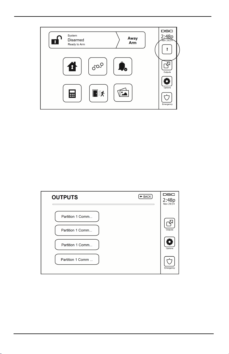
Outputs
Your installer may have programmed these keys to perform various functions (reset smoke detector after an alarm,
open your garage door, etc.) To activate these functions, press Output and then press the appropriate option. For
additional information, refer to the section: Sensor reset.
Figure 6- Outputs
- 15 -
Page 16

Additional Functions
Additional Functions
Photos
You can create a slideshow of photos to View on the keypad. Photos are added using an SD card (32x24x2.1 mm.
Not suppli ed).
The photos must be .jpg format and can be up to 1280 x 720 in size. For best results, use 800 x 480 resolution.
Use photo editing software to adjust the size of your photos.
To start the slideshow, set the screen saver to photo mode. The slideshow plays automatically until the timeout is
reached or the screen is touched again.
To add photos:
1. Press Options, User Functions, Keypad Config, Picture Frame, Select Photos. Thumbnail i mages of the photos
on your SD card are displayed.
2. Touch an image to add it to the slideshow. Touch it a second time to remove it.
Use the Transition Time slider to program the amount of time each photo is on screen, from 5 seconds to 1
minute.
Use the Photo Frame Timeout slider to control how long your slideshow plays for, from 1 minute to 2 hours.
Select Never to keep the slideshow runni ng until the screen is touched.
Note: Maximum of 255 photos are supported.
Quick Exit
If the system is armed and you need to exi t, use the quick exit function to avoid disarming and rearming the system. To activate this function, tap the Quick Exit icon. You have 2 minutes to leave the premises through your
exit door. When the door i s closed again the remaining exit time is canceled.
Time & Date Programming
Tap on Options. Select User Functions [Master Code] and then select Time & Date. Tap on t he section you would
like to change and use the up/down arrows to change time/date. Once done, press Save.
Keypad Mode
This option allows the HS2TCHPRO/HS2TCHPROBLK Touchscreen to function as a traditional DSC keypad.
Door Chime (Chime enable/disable)
The keypad indicates the current state of the door chime function (Enabled or Disabled). To choose the opposite
function, tap the 'Chime' icon. Three beeps indicate that the chime is ON (Enabled). One long beep indicates that
chime is OFF (Disabled).
Note: The door chime feature should be used i n Disarmed mode only.
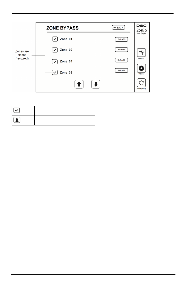
Zone Bypass
This screen allows you to view the status of the zones on the system.
- 16 -
Page 17
Options Menu
Figure 7- Zone Cl osed
Zone Status Indicators
Ready Zone is closed
Open The zone is open and needs to be closed
Bypassed Zones
Use the zone bypass feature when a zone is open but the system needs to be armed. Bypassed zones will not cause
an alarm when opened. Bypassing zones reduces the level of security. If you are bypassing a zone because it is not
functioning, call a service t echnician immediately so that the problem can be resolved and your system returned to
proper working order.
Ensure that no zones are unintentionall y bypassed when arming your system. Zone bypassing can only be performed while the system is disarmed. Bypassed zones are automatically canceled each time the system is disarmed
and must be bypassed again, if required, before the next arming.
Note: 24-hour zones can only be unbypassed manually.
Note: For security reasons, your installer has programmed the system to prevent certain zones from being
bypassed. (e.g., smoke detectors).
Bypassing Zones with a HS2TCHPRO/HS2TCHPROBLK
When in the Zone Status page, scroll up/down through the desired zones, and tap on the bypass icon to bypass
the zone. To unbypass a zone, tap t he unbypass icon.
Note: For UL listed installations, zones can only be bypassed manually.
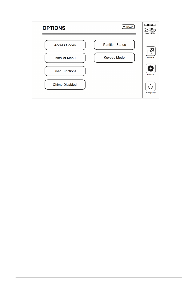
Options Menu
Access the following functions by pressing Options on the right side of the home page. See the online
HS2TCHPRO/HS2TCHPROBLK User Manual for more information.
l Access Codes
l Installer Menu
l User Functions
l Chime Enabled/Disabled
l Partition Status
l Keypad Mode
- 17 -
Page 18
Options Menu
Figure 8- Options
Access Codes
When Access Codes is selected from the Options menu, the keypad prompts for a Master Code. When a valid
Master Code is entered, a numeric keypad is displayed with arrows to scroll through the list of users. Press the
Select button to enter the user options.
Set Access Code: adds/edits the 4-digit or 6-digit code
Set Partitions: assigns the user to partitions
User Options: enables/disables different options for the user
Delete User: deletes the user from the system
The access codes have programmable attributes which allow zone bypassing, or one-time use activation.
Master Code (Access Code 01): The master code, if programmed, can only be changed by the installer.
Supervisor Codes: These codes can be used to program additional codes which have equal or lesser attributes.
Once programmed, the supervisor codes receive the master code’s attributes. These attributes are changeable. Any
user code can be made a supervisor code by enabling User Code Attribute 1 (see the following for details).
Duress Codes: Duress codes are standard user codes that transmit the Duress Reporting Code when entered to
perform any function on the system. Any user code can be made a duress code by enabling User Code Attribute 2
(see the following for details).
Note: Duress codes are not valid when entering User Programming, Master Functions or Installer’s sections.
Note: Access codes cannot be programmed as a duplicate or as a “Code +/- 1”.
Assign Proximity Tags
Depending on how your keypad is programmed, proximity tags can be used to either arm/disarm the system or to
perform a programmed function (e.g. unlock a cabinet or storeroom door). Present the tag to the tag reader.
1. Press [*][5]Master/Supervisor Code].
2. Enter a 4-digit or 6-digit user code.
3. Press 2.
4. Pass the enrolled tag near the tag reader.
Delete Proximity Tags
To delete a proximity tag:
1. Select Options, Access Codes [enter Master code].
2. Select a user to delete.
- 18 -
Page 19

Options Menu
3. Select Prox Tag Prog then delete.
User Code Attributes
1. The default attributes of a new code will be the attributes of the code used to enter User Programming
whether it is a new code or an existing code being programmed.
2. System Master Code 01 has partition access for all partitions, as well as attributes 3-4 ON by default.
Note: These attributes are not changeable.
Inherent Attributes (all codes except installer and maintenance)
Arm/Disarm: Any access code with partition access enabled wi ll be valid for arming and disarming that par-
tition.
Command Outputs ([*][7][1], [*][7][2], [*][7][3], and [*][7][4]): If these outputs require access code
entry, any Access Code with partit ion access will be valid for performing the command output functions on that
partition.
Programmable Attributes
1. Supervisor Code 5. For Future Use
2. Duress Code 6. For Future Use
3. Zone Bypassing Enabled 7. Bell Squawk upon Arming/Disarming
4. Remote Access 8. One Time Use Code
Bell Squawk Attribute
This attribute is used to determine whether an access code should generate an arming/disarming Bell Squawk upon
entry of the code for Away arming. The wireless keys with access codes associated with them may generate Arming/Disarming Bell squawks. If desired, this option may be used with codes that are manually entered. Please contact your installer to have this programmed.
Note: The Master Code cannot use the Bell Squawk attribute, but is required to enable it for other codes.
Note: This feature cannot prevent the Arming/Disarming squawks from being generated if an access code assigned
to a wireless key is manually entered at a keypad.
Note: This feature is used to annunciate fire trouble signals and also trouble conditions for medical applications.
Partition Assignment
1. This section is used to assign users to available partitions. To assign partitions:
2. Select Options > Access Codes.
3. Enter the master code.
4. Select a user.
5. Select Partition Attributes.
6. Select the partition(s) to assign to the user.
Notes on Access Codes and Programming
l The master code’s attributes cannot be changed.
l When a new code is programmed in User Programming it will be checked against all other codes in the
system. If a duplicate code is found, an error tone is given and the code i s returned to what it was before
it was changed. This applies to both 4 and 6-digit codes.
Erasing an Access Code
To erase a code, select the code and choose Delete User. The system will delete the code immediately and the user
will be returned to select another code.
Installer Menu
These functions are for the installer’s use only.
- 19 -
Page 20

Options Menu
User Functions
First disarm the system then enter Options, User Functions, then Master Code. This command is used to gain
access to the fol lowing list of master functions of the system:
Time and Date
Enter desired time and date.
Auto-Arm Time
The system can be programmed to arm at a programmed time each day, per partition. Upon entry of this section,
enter the desired Auto-Arm time for each day of the week.
At the selected Auto-Arm time, the keypad buzzers will sound for a programmed amount of time (programmable
by the installer only) to warn that an auto-arm is in progress. The bell can also be programmed to squawk once
every 10 seconds during this warning period. When the warning period is complete, the system will arm with no
exit delay and in Away mode.
Auto-Arming can be canceled or postponed by entering a vali d access code only during the programmed warning
period. Auto-Arming will be attempted at the same time the next day. When the Auto-Arming process is canceled
or postponed, the Auto-arm Cancelation Reporting Code will be transmitted (if programmed).
If arming is inhibited by one of the following, the Auto-Arm Cancelation transmission will be communicated:
l AC / DC Inhibit Arm
l Latching System Tampers
l Zone Expander Supervisory Fault
Note: For UL/ULC listed installations, the auto-arm feature shall be canceled when there are zones in an off-normal condition.
Enable DLS/Allow System Service
If enabled, the installer will be able to access Installer Programming via remote (DLS). The DLS window will
remain open for 6 hrs, during which time the inst aller will be able to enter DLS an unlimited number of times.
After the 6-hr window has expired, Installer’s Programming will be unavailable again until the window is reopened.
Event Buffer
l Displays the date, time and the full description of the event
l The Log is organized from the most recent event (Top) to past events (Down)
l The Left arrow scrolls forward in time
l The Right arrow scrolls back in time
l The Back returns you to the Home screen
l This screen will time out to the Home screen after 30 seconds of inactivity
System Test
The system’s bell output, keypad lights and communicator are tested. This test will also measure the panel’s
standby battery.
Important:
l To ensure that your system continues to function as intended, you must test your system weekly.
l For UL HOME HEALTH CARE listed appli cations, the system shall also be tested weekly without AC
power. To remove AC from the control unit, remove the screw from the restraining tab of the plug in
adapter and remove the adapter from the AC outlet. After completing the test of the unit using only the
battery backup source, reconnect the plug in adapter and attach the screw through the restraining tab, so
that the adapter is securely attached to the outlet.
l Should your system fail to function properly, contact your installation company immediately.
- 20 -
Page 21
Options Menu
l All smoke detectors must be tested by your smoke detector installer once a year to ensure proper oper-
ation.
Auto-Arm/Disarm Control
Pressing Auto-Arm while in the User Function menu will enable (three beeps) or disable (one long beep) the
Auto-Arm and Auto-Disarm feature, by partition. Wi th thi s feature enabled, the panel will automatically arm in
Away mode (Stay/Away zones active) or disarm at the same time each day. The Auto-Arm time is programmed
with the Auto-Arm time button. Auto-Disarm must be programmed by the syst em installer.
User Call-up
This option gives your service provider temporary access to the alarm control panel for remote servicing.
Engineer's Reset
If an alarm has occurred on your system, the system will not allow you to rearm (Ready light is OFF). You will
need to contact your installer. They will check and reset the system for you. This may involve a visit to check
your system. After the reset is performed, your system will function properly again.
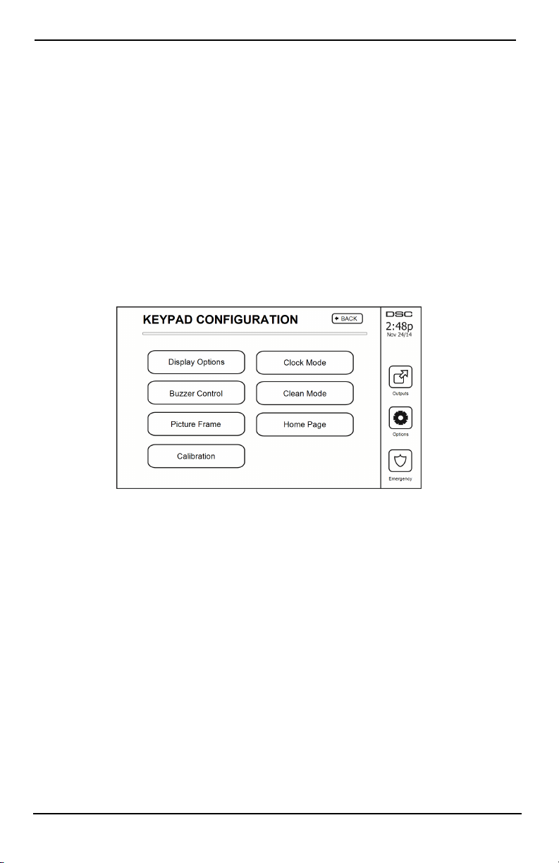
Keypad Configuration
Figure 9- Keypad Configuration
Display Options: sets the brightness and screen timeout of the Touchscreen, as well as screen saver options.
Buzzer Control: sets the buzzer volume of the Touchscreen. Note: For SIA CP-01, the buzzer volume shall not
be placed at the minimum setting.
Note: For UL/ULC installations, the buzzer level shall not be changed from the default level.
Picture Frame: selects the pictures that will be displayed on the slideshow.
Calibration: calibrates the Touchscreen.
Clock Mode: displays the digital clock.
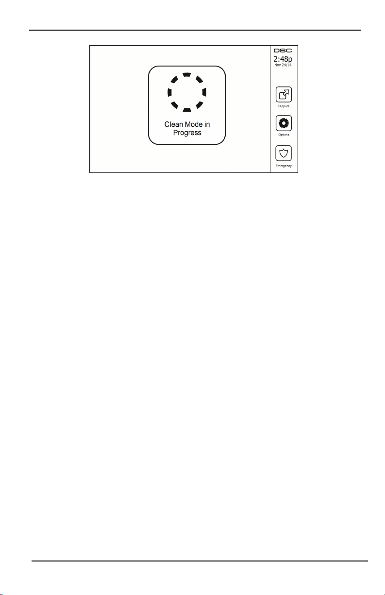
Clean Mode: allows the user to touch (i.e., clean) the screen without enabling or disabling any functions. The
screen will remain in this mode for 30 seconds, then return to the Keypad Configuration screen.
- 21 -
Page 22
Options Menu
Figure 10- Clean Mode
Home Page: can be configured in one of two different views, Classic (square buttons) and Contemporary
(rondel).
Chime Enabled/Disabled
Door Chime: To turn the door chime function On/Off, tap t he Chime icon. 3 beeps indicate that the chime is
ON. 1 long beep i ndicates the Chime is OFF.
Arming
Stay Arm: arms the system in Stay mode
Away Arm: arms the system in Away mode
Night Arm: To fully arm the syst em when it has been armed in Stay Mode, press Night Arm button. All interior
zones will now be armed except for devices programmed as Night Zones. Night zones are only armed in Away
mode. Thi s permits limited movement within the premises when the system is fully armed. Ensure that your
installer has provided you with a list identifying zones programmed as night 18 zones. When the interior zones
have been activated (i.e., Night Arm), you must enter your access code to disarm the system to gain access to
interior areas that have not been programmed as night zones.
Quick Exit: refer to the section: Quick Exit
Global Away Arm: arms all partitions to which the User Code is assigned, in Away mode.
Global Stay Arm: arms all partitions to which the User Code is assigned, in Stay mode.
No Entry Arm: arms the system with no entry.
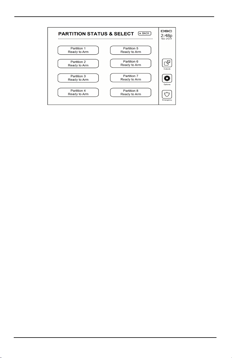
Partition Status
To view the partition status, press Options, User Functions, then Partition Status. The keypad shows basic status
for up to 8 partitions, depending on the configuration of your system. Each partition is identified along with its
current status.
- 22 -
Page 23
Managing Partitions
Figure 11- Partition Status
Keypad Mode
This option allows the HS2TCHPRO/HS2TCHPROBLK Touchscreen to function as a traditional DSC keypad.
Managing Partitions
A partition is a limited area of the premises which operates i ndependently from the other areas. Partitioning a system can be beneficial if the property has outbuildings that need to be secured independently of a main area or if
the home has a separate apartment. Each partition can have it s own keypad, or a keypad can have access to all partitions. User access to partitions is controlled via access code. A master code can access the entire system and partitions, while a user code is limited to assigned partitions.
Partitions
Keypads can be configured to control an individual partition or all partitions.
Note: Access to this feature must be configured by your installer.
Single Partition Operation
Single partition keypads provide access to alarm functionality for an assigned partition.
Single partition keypads behave as follows:
l Displays the armed set state of the partition.
l Displays open zones, if assigned to the partition the keypad is on.
l Displays bypassed zones and allows zone bypassing or creating bypass groups of zones assigned to the
keypad partition.
l Displays system troubl es (system low battery, system component faults/tampers).
l Displays alarms in memory that occurred on the partition.
l Allows the door chime to be Enabled/disabled.
l System test (sounds bells/PGMs assigned to the partition).
l Label programming (zone, partition and user labels for the partition).
l Command output controls (outputs assigned to the partition, or global outputs such as smoke detector
reset).
l Temperatures.
Loaning a Keypad to Another Partition
The HS2TCHPRO/HS2TCHPROBLK Touchscreen Keypad can be loaned to operate on other partiti ons. When a
keypad is loaned to another partition, it will behave on the loaned partition as if it was originally assigned there.
An access code must be entered before loaning a keypad to another partition. An access code is also required to
perform any function on that partition.
- 23 -
Page 24

Managing Partitions
To loan a keypad to another partition:
1. Select Options > Partition Status.
2. Enter your access code.
3. Select the partition to loan the keypad to. If the keypad is inactive for more than 30 seconds, it will
return to its original partition.
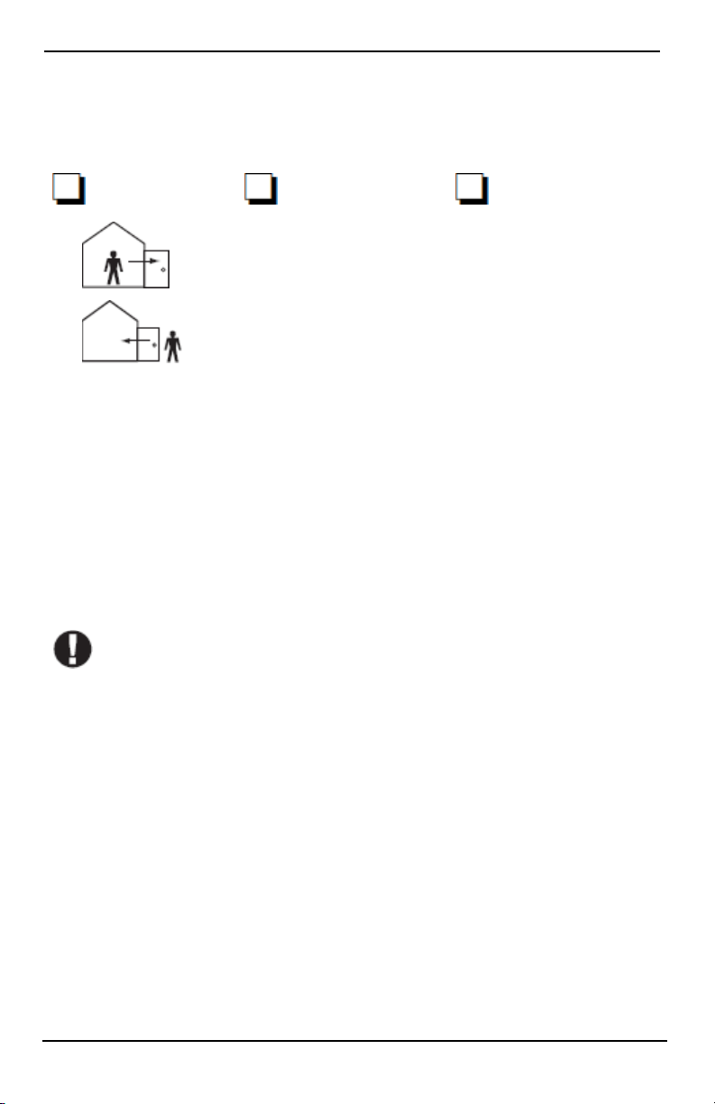
Global Keypad Operation
Once a valid access code is entered, a global keypad will display the status of any partitions that the user has permission to view. From this overview, you can loan the global keypad to a partition, arm all partitions or disarm
all partitions. The status of each partition will be identified by a partition status icon. For an explanation of partition status icons, see the table below. The global arm and global disarm buttons will arm or disarm all displayed
partitions.
To Loan a Global Keypad to Another Partition:
1. Select Partition Status.
2. Select the partition to loan the keypad to.
Figure 12- Global Keypad Mode
Partition
Status Icon
Description
GREEN BACKGROUND
Partition is ready to be armed
Partition is in exit delay
GRAY BACKGROUND
Partition is not ready to be armed
Partition is in alarm
Partition is in entry delay
Partition is armed
- 24 -
Page 25

Managing Partitions
Fire and CO Zone Types
l If a Fire zone generates an alarm only the partition the fire zone is assigned to will go into alarm. Other
partitions retain their current state.
l If the [F] key on a global keypad is used to generate an alarm all enabled partitions will go into alarm.
l One or more fire keypads may be located on any partition.
l On alarm, the fire auto-scroll display appears on all partition keypads and on all global keypads. Fire
alarm silence and fire system reset may be done directly on any partition keypad. To silence a fire or CO
alarm from a global keypad requires that the global keypad be loaned to one of the partitions.
- 25 -
Page 26

Testing Your System
Testing Your System
Note: If you are going to perform a System Test, call your Monitoring Station to inform them when you begin and
also when you end the test.
Testing Your Keypad Sounder and Siren
The System Test performs a two-second check of the keypad sounder and bell or siren, in addition to testing the
keypad status lights and the panel backup battery.
1. Press Options, User Functions [Master Code], then System Test. The following will occur:
- The system activates all keypad sounders and bells or sirens for 2 seconds. All keypad lights turn ON.
- The Ready, Armed, and Trouble LEDs will flash for the duration of the test.
2. To exit the function menu, press [#].
Testing Your Entire System
All smoke detectors in this installation must be tested by your smoke detector inst aller or dealer once a year to
ensure they are functioning correctly. It is the user’s responsibility to test the system weekly (excluding smoke
detectors). Ensure you follow all the steps in the “Testing Your Keypad Sounder and Siren” section.
Note: Should the system fail to function properly, call your installation company for service immediately.
1. Prior to testing, ensure that the system is disarmed and the Ready light is on.
2. Close all zones to return the system to the Ready state.
3. Perform a Syst em Test by following the steps in the “Testing Your Keypad Sounder and Siren” section.
4. To test the zones, activate each detector in turn (e.g., open each door/window or walk in motion detector
areas).
On an HS2TCHPRO/HS2TCHPROBLK keypad, the following message will be displayed when each zone
(detector) is activated: “Ready to Force,” “Not Ready”. Use the zone status but ton t o view which zones are open.
The message wi ll disappear when the zones are closed.
Note: Some features described above will not be functional unless enabled by your installer. Ask your installer
which features are functional on your system.
Walk Test Mode
The installer can initiate a Walk Test mode for the system. While in Walk Test mode, the Ready, Armed, and
Trouble LEDs will flash to indi cate that Walk Test i s active. When the system automatically terminates the Walk
Test mode, it will annunciate wi th an audible warning (5 beeps every 10 seconds), beginni ng five minutes prior to
the termination of the test.
Allowing Computer Access To Your System
From time to time, your installer may need to send information to or retrieve information from your security system. Your installer will do this by having a computer call your system over the telephone line. You may need to
prepare your system to receive this ‘downloading’ call. To do t his, press Options, User Functions [Master Code],
then System Serv/DLS from the Touchscreen. This allows downloading for a limited period of time. During this
time, the system will answer incoming downloading calls. For more information on this feature, please ask your
installer.
- 26 -
Page 27
Reference Sheets
Reference Sheets
Fill out the following information for future reference and store this guide in a safe place.
System Information Enabled?
[F] FIRE [+] Medical [P] PANIC
The Exit Delay Time is ___ seconds
The Entry Delay Time is ___ seconds
For Service
Central Station Information:
Account #: ________________ Telephone #: ________________
Installer Information:
Company #: ________________ Telephone #: ________________
Battery Installation / Service Date:
__________________________
__________________________
__________________________
If you suspect a false alarm signal has been sent to the central monitoring station, call the station to
avoid an unnecessary response.
- 27 -
Page 28

Access Codes (copy as needed)
HS3032/HS3128/HS3248 MASTER CODE [01]: ______________________
User Access Code User Access Code User
01 35 69
02 36 70
03 37 71
04 38 72
05 39 73
06 40 74
07 41 75
08 42 76
09 43 77
10 44 78
11 45 79
12 46 80
13 47 81
14 48 82
15 49 83
16 50 84
17 51 85
18 52 86
19 53 87
20 54 88
21 55 89
22 56 90
23 57 91
24 58 92
25 59 93
26 60 94
27 61 95
28 62 96
29 63 97
30 64 98
31 65 99
32 66 100
33 67
34 68
Reference Sheets
- 28 -
Page 29

Reference Sheets
Sensor / Zone Information (copy as needed)
Zone Protected Area Sensor Type
1
2
3
4
5
6
7
8
9
10
11
12
13
14
15
16
17
18
19
20
21
22
23
24
25
26
27
28
29
30
- 29 -
Page 30

Guidelines for Locating Smoke Detectors and CO Detectors
Guidelines for Locating Smoke Detectors and CO
Detectors
The following information is for general guidance only and it is recommended that local fire codes and regulations be consulted when locating and installing smoke and CO alarms.
Smoke Detectors
Research has shown that all hostile fires in homes generate smoke to a greater or lesser extent. Experiments with
typical fires in homes indicate that detectable quantities of smoke precede detectable levels of heat in most cases.
For these reasons, smoke alarms should be installed outside of each sleeping area and on each storey of the home.
The following information is for general guidance only and it is recommended that local fire codes and regulations be consulted when locating and installing smoke alarms. It is recommended that additional smoke alarms
beyond those required for minimum prot ection be installed. Additional areas that should be protected include: the
basement; bedrooms, especially where smokers sleep; dining rooms; furnace and util ity rooms; and any hallways
not protected by the required units. On smooth ceilings, detectors may be spaced 9.1m (30 feet) apart as a guide.
Other spacing may be required depending on ceiling height, air movement, the presence of joists, uninsulated ceilings, etc. Consul t National Fire Alarm Code NFPA 72, CAN/ULC-S553-02 or other appropriate national standards
for installation recommendations.
l Do not locate smoke detectors at the top of peaked or gabled ceilings; the dead air space in these loc-
ations may prevent the unit from detecting smoke.
l Avoid areas with turbulent air flow, such as near doors, fans or windows. Rapid air movement around
the detector may prevent smoke from entering the unit.
l Do not locate detectors in areas of high humidity.
l Do not locate detectors in areas where the temperature rises above 38°C (100°F) or falls below 5°C
(41oF).
Smoke detectors should always be installed in USA in accordance with Chapter 29 of NFPA 72, the National Fire
Alarm Code: 29.5.1.1.
Where requi red by other governing l aws, codes, or standards for a specific type of occupancy, approved singleand multiple-station smoke alarms shall be installed as follows:
1. In all sleeping rooms and guest rooms.
2. Outside of each separate dwelling unit sleeping area, within 21 ft (6.4 m) of any door to a sleeping
room, with the distance measured along a path of travel.
3. On every level of a dwelling unit, including basements.
4. On every level of a residential board and care occupancy (small facility), including basements and
excluding crawl spaces and unfinished attics.
5. In the living area(s) of a guest suite.
6. In the living area(s) of a residential board and care occupancy (small facility).
- 30 -
Page 31

Guidelines for Locating Smoke Detectors and CO Detectors
Carbon Monoxide Detectors
Carbon monoxide is colorless, odorless, tasteless, and very toxic. It also moves freely in the air. CO detectors can
measure the concentration and sound a loud alarm before a potentially harmful level is reached. The human body
is most vulnerable to the effects of CO gas during sleeping hours; therefore, CO detectors should be located in or
as near as possible to sleeping areas of the home. For maximum protection, a CO alarm should be located outside
primary sleeping areas or on each level of your home. Figure 5 indicates the suggested locations in the home.
Do NOT place the CO alarm in the following areas:
l Where the temperature may drop below -10ºC or exceed 40ºC
l Near paint thinner fumes
l Within 5 feet (1.5m) of open flame appliances such as furnaces, st oves and fireplaces
l In exhaust streams from gas engines, vent s, flues or chimneys
l Do not place in close proximity to an automobile exhaust pipe; this will damage the detector
PLEASE REFER TO THE CO DETECTOR INSTALLATION AND OPERATING INSTRUCTION SHEET FOR
SAFETY INSTRUCTIONS AND EMERGENCY INFORMATION.
- 31 -
Page 32

Guidelines for Locating Smoke Detectors and CO Detectors
Household Fire Safety Audit
Read this section for important information about fire safety. Most fires occur in the home. To minimize this
danger, we recommend that a household fire safety audit be conducted and a fire escape plan be developed.
1. Are all electrical appliances and outlets in a safe condition? Check for frayed cords, overloaded lighting
circuits, etc. If you are uncertain about the condition of your electrical appliances or household service,
have a professional evaluate these units.
2. Are all flammable liquids stored safely in closed containers in a well-ventilated cool area? Cleaning
with flammable liquids should be avoided.
3. Are fire-hazardous materials (e.g., matches) well out of reach of children?
4. Are furnaces and wood-burning appliances properly installed, clean and in good working order? Have a
professional evaluate t hese appliances.
Fire Escape Planning
There is often very little time between the detection of a fire and the time it becomes deadly. It is thus very important that a family escape plan be developed and rehearsed.
1. Every family member should participate in developing the escape plan.
2. Study the possible escape rout es from each l ocati on within the house. Since many fires occur at night,
special attention should be given to the escape routes from sleeping quarters.
3. Escape from a bedroom must be possible without opening the interior door.
Consider the following when making your escape plans:
l Make sure that all border doors and windows are easily opened. Ensure that they are not painted shut,
and that their locking mechanisms operate smoothly.
l If opening or using the exit is too difficult for children, the elderly or handicapped, plans for rescue
should be developed. This includes making sure that those who are to perform the rescue can promptly
hear the fire warning signal.
l If the exit is above t he ground level, an approved fire ladder or rope should be provided as well as train-
ing in its use.
l Exits on t he ground level should be kept clear. Be sure to remove snow from exterior patio doors in
winter; outdoor furniture or equipment should not block exits.
l Each person should know the predetermined assembly point where everyone can be accounted for (e.g.,
across the street or at a neighbour’s house). Once everyone is out of the building, call the fire department.
l A good plan emphasizes quick escape. Do not investigate or attempt to fight the fire, and do not gather
belongings as this can waste valuable time. Once outside, do not re-enter the house. Wait for the fire
department.
l Write the fire escape plan down and rehearse it frequently so that should an emergency arise, everyone
will know what to do. Revise the plan as conditions change, such as the number of people in the home,
or if there are changes to the building’s constructi on.
l Make sure your fire warning system is operational by conducting weekly tests. If you are unsure about
system operation, contact your installer.
l We recommend that you contact your local fire department and request further information on fire safety
and escape planning. If available, have your local fire prevention officer conduct an in-house fire safety
inspection.
- 32 -
Page 33

License Agreement
IMPORTANT - READ CAREFULLY: DSC Software purchased w ith or w ithout P roducts and Components i s copyrighted and is purchased under the following license
terms:
- This End-User License Agreement (“EULA”) is a legal agreement between Y ou (the company, individual or entity who acquired the Software and a ny related Hardware)
and Digital Security Controls, a division of Tyco Safety Products Canada Ltd. (“DS C”), t he manufacturer of the integrated security systems and t he developer of the s oftware and any related products or components (“HARDWARE”) which You acquired.
- If the DS C software product (“SOFTWARE PRODUCT” or “SOFTWARE”) is intended to be accompanied by HA RDWARE, and is NOT accompanied by new
HARDWARE, You may not use, copy or instal l the SO FTWARE P RODUCT. The SOFTWARE PRODUCT includes computer software, and may include as sociated
media, printed materials , and “online” or electronic documentation.
- A ny s oftware provided along with the Software Product that is as sociated wit h a separate end-user l icense agreement is l icensed to You under t he t erms of that license
agreement.
- By install ing, copying, downloading, storing, access ing or otherwise usi ng the Software P roduct, You agree unconditionally to be boundby the terms of this EULA, even
if this EULA is deemed to be a modification of any previous arrangement or contract. If Y ou do not agree to the terms of this EULA, DSC is unwilling to li cense the Software Product to You, and You have no right to use it .
SOFTWARE PRODUCT LICENSE
The S OFTWARE PRODUCT is protected by copyright law s and international copyright treaties , as well as other intellect ual property laws and treaties . The
SOFTWARE PRODUCT is licensed, not sold.
1. GRANTOFLICENSE This EULA grants You the followingrights:
(a)Software Install ation a nd Us e - For each license You acquire, You may have only one copy of the SOFTWARE PRODUCT insta lled.
(b)Storage/Network Use - The S OFTWARE PRODUCT may not be install ed, accessed, displayed, run, shared or used concurrently on or from different computers, includ-
ing a w orkstation, t erminal or other digital electronic device (“Device”). In other words, if You have s everal workstations, You will have to acquire a license for e ach
workstation where the SO FTWARE w ill be used.
(c)Backup Copy - You may make back-up copies of t he S OFTWARE PRODUCT, but You may only have one copy per license inst alled at any given time. You may use
the back-up copy solely for archival purposes. Except as expressly provided in this EULA, You may not otherwise make copies of the SOFTWARE PRODUCT, i ncluding
the printed materials accompanying the S OFTWARE.
2. DESCRIPTION OF OTHER RIGHTS AND LIMITATIONS
(a) Limit ations on Reverse Engineering, Decompilation and Di sassembly - Y ou may not reverse engineer, decompile, or disassemble t he S OFTWARE PRODUCT, except
and only to the extent that s uch activity is expressly permitted by applicable l aw notwithstanding this limitation. Y ou may not make any changes or modifications to the
Software, wit hout the writt en permission of an officer of DSC. Y ou may not remove any proprietary notices, marks or labels from the Software P roduct. You shall institute reasonable meas ures to ensure compliance wit h t he terms and conditions of this EULA .
(b) Separation of Components - The Software Product is licensed as a si ngle product. Its component parts may not be s eparated for use on more than one HARDWARE
unit.
(c) S ingle INTEGRATED PRODUCT - If You acquired this SOFTWARE with HA RDWARE, then the SO FTWARE P RODUCT i s li censed with the HARDWARE as
a single integrated product. In this cas e, the S OFTWARE PRODUCT may only be used with the HARDWARE as s et forth in this EULA.
(d) Rental - You may not rent, lease or l end the S OFTWARE PRODUCT. You may not make it available t o others or post it on a s erver or web sit e.
(e) S oftware P roduct Transfer - You may transfer all of Your rights under this EULA only as part of a permanent sale or transfer of the HARDWARE, provided You retain
no copies, You transfer all of the S OFTWARE PRODUCT (including all component parts, the media a nd printed materials, any upgrades and this EU LA), and provided
the recipient agrees to the terms of this EULA . If the SOF TWARE P RODUCT is an upgrade, any transfer must also include all prior versions of the S OFTWARE
PRODUCT.
(f) Termination - Without prejudice to any other rights, DS C may terminate this EULA if Y ou fail t o c omply with the terms and conditions of this EULA. In such event,
You must des troy all copies of t he S OFTWARE PRODUCT and al l of its component parts.
(g) Trademarks - This EULA does not grant You any rights in connection wit h any trademarks or s ervice marks of DS C or its suppliers.
3. COPYRIGHT
All ti tle and intellectual property rights in and t o t he S OFTWARE PRODUCT (includingbut not limited to any images, photographs, and text incorporated i nto the
SOFTWARE PRODUCT), the accompanying printed materials, and any copies of the SOF TWARE P RODUCT, are owned by DSC or i ts s uppliers. You may not copy
the printed materials accompanying the S OFTWARE PRODUCT. All title and intellectual property rights in and to the content which may be acces sed through use of the
SOFTWARE PRODUCT are the property of the res pective content owner and may be protected by applicable copyright or other intellectual property laws and treaties.
This EULA grants You no rights t o use such content. A ll rights not expressly granted under this EULA are reserved by DS C and its suppliers.
4. EXPORT RESTRICTIONS
You agree that You will not export or re-export the SO FTWARE P RODUCT to any country, person, or entity subject to Canadian export rest rictions.
5. CHOICE OF LAW
This Software License Agreement is governed by the laws of the Province of Ontario, Canada.
6. ARBITRATION
All disputes arising in connection with this Agreement s hall be determined by final and bindingarbitration in accordance wit h t he Arbitration Act, andt he parties agree to
be bound by the arbitrator’s decision. The place of arbitration s hall be Toronto, Canada, and the language of the arbitration shall be English.
7. LIMITED WARRANTY
(a) NO WARRANTY - DSC PROVIDES THE SOFTWARE “AS IS” WITHOUT WARRANTY. DSC DOES N OT WARRANT TH AT THE SO FTWARE WILL
MEET YOUR REQUIREMENTS OR THAT OPERATION O F THE S OFTWARE WILL BE UNINTERRUPTED OR ERROR-FREE.
(b) CHANGES IN OPERATING ENV IRONMENT - DSC shall not be responsible for problems c aused by changes in the operating characteristics of the HARDWARE,
or for problems in the interaction of the SO FTWARE P RODUCT with non-DSC-SOFTWARE or HARDWARE P RODUCTS.
(c) LIMITATION OF LIABILITY - WARRANTY REFLECTS A LLOCATION OF RISK - IN ANY EVENT, IF A NY S TATUTE IMPLIES WARRANTIES OR
CONDITIONS NOT STATED IN TH IS LICENSE AGREEMENT, DS C’S EN TIRE LIABILITY UND ER A NY PROVISION OF TH IS LICENSE AGREEMENT
SHALL BE LIMITED TO THE GREATER OF TH E AMOUN T ACTUALLY PAID BY YOU TO LICENSE THE SOF TWARE P RODUCT A ND FIVE
CANADIAN DO LLARS (CAD$5.00). BECAUSE SOME J URISDICTIONS DO N OT ALLOW THE EXCLUSION ORLIMITATION O F LIABILITY F OR
CONSEQUENTIAL OR INCIDENTAL DAMA GES, THE ABOVE LIMITATION MAY NOT AP PLY TO YOU.
(d) DISCLAIMER OF WARRANTIES - THIS WARRANTY CONTAINS THE ENTIRE WARRANTY AND S HALL BE IN LIEU OF ANY A ND ALL OTHER
WARRANTIES, WHETHER EXP RESSED OR IMPLIED (INCLUDING ALL IMPLIED WARRANTIES OF MERCHANTABILITY OR FITNESS FOR A
PARTICULAR PURPOS E) AND O F ALL O THER O BLIGATIONS OR LIABILITIES ON THE PART OF DSC. DS C M AKES N O OTHER WARRANTIES. DSC
NEITHER AS SUMES NOR AUTHORIZES AN Y OTHER PERSON PURPORTING TO A CT ON ITS BEHALF TO MODIFY OR TO CHANGE THIS
WARRANTY, NOR TO AS SUME F OR IT ANY O THER WARRANTY OR LIABILITY CONCERNING THIS SOF TWARE P RODUCT.
(e) EXCLUSIVE REMEDY AND LIMITATION OF WARRANTY - UNDER NO CIRCUMSTANCES SH ALL DSC BE LIABLE FO R A NY S PECIAL,
INCIDENTAL, CONSEQUENTIAL O R INDIRECT DAMAGES BASED U PON BREACH OF WARRANTY, BREACH O F CONTRACT, NEGLIGENCE, STRICT
LIABILITY, OR AN Y OTHER LEGAL TH EORY. SUCH D AMAGES INCLUDE, BUT ARE NOT LIMITED TO, LOSS OF P ROFITS, LOSS O F THE
SOFTWARE PRODUCT OR ANY ASSO CIATED EQ UIPMENT, COST OF CAPITAL, COST OF SUBSTITUTE OR REPLACEMENT EQUIPMENT,
FACILITIES OR SERVICES, DOWN TIME, PURCHASERS TIME, THE CLAIMS OF THIRD PA RTIES, INCLUDING CUSTOMERS, A ND INJ URY TO
PROPERTY.
Page 34

WARNING: DSC recommends that t he e ntire system be completely test ed on a regular bas is. However, despite frequent tes ting, and due to, but not limited to, criminal
29010530R002
tampering or elec trical disruption, it is possible for this S OFTWARE PRODUCT to fail to perform as expected.
FCC Compliance Sta tementCAUTION:Changes or modifications not expressly approved by DSC could void your authority to use this equipment.
This equipment generates and uses radio frequency energyand if not install ed a nd used properly, in strict accordance wi th the manufacturer’s instructions, may cause interference to radio and televis ion reception. It has been type test ed and found to comply with the limit s for Class B device in accordance wit h t he specifications in Subpart
“B” of Part 15 of F CC Rules, w hich are des igned to provide reasonable protection against s uch interference in any residential installat ion. However, there is no guarantee
that interference wil l not occur in a particular install ation. If this equipment does cause interference to televis ion or radio reception, which can be determined by turning the
equipment off and on, t he user is encouraged to try to correct the interference by one or more of the following meas ures:
- Re-orient t he receiving antenna
- Relocate t he alarm control wit h res pect to the receiver
- M ove the alarm control aw ay from the receiver
- Connect t he alarm control into a different outlet s o that alarm control and receiver are on different circuits.
If necess ary, the user should consult the dealer or an experienced radio/television technician for additional s uggestions. The user may find the following booklet prepared by
the FCC helpful: “How to Identify and Resolve Radio/ Tel evision Interference Problems”. This booklet is available from the U.S . Government Printing Office, Washington, D. C. 20402, Stock # 004-000-00345-4.
This Class Bdigital apparatus complies with CAN ICES-3(b)/nmb-3(b).
EN50131-1 Grade3/Class II
The Model HS 2TCHPRO/HS2TCHPROBLK Keypad has been certified by Telefication according to EN50131-1:2006 + A 1:2009 + A2:2017, EN50131-3:2009 for Grade 3,
Class II.
Note: For EN50131 compliant installations the following functions (initiated from the keypad emergency buttons) have to be disabled:
- F ire Alarm function
- A uxiliary (Medical) Alarm function
- P anic Alarm function
© 2018 Tyco Security Products. All Rights Reserved Toronto, Canada • www.dsc.com
The trademarks, logos, and service marks displayed on this document are registered in the United States [or other
countries]. Any misuse of the trademarks is strictly prohibited and Tyco will aggressively enforce its intellectual
property right s to the fullest extent of the law, including pursuit of criminal prosecution wherever necessary. All
trademarks not owned by Tyco are the property of their respective owners, and are used with permission or
allowed under applicable laws. Product offerings and specifications are subject to change without notice.
Actual products may vary from photos. Not all products include all features. Availability varies by region; contact
your sales representative.
Page 35

Uživatelská příručka dotykové obrazovky
HS2TCHPRO/HS2TCHPROBLK
UPOZORNĚNÍ: Tato příručka obsahuje informace oomezeních týkajících se používání výrobku ajeho funkcí
ataké informace oomezení odpovědnosti výrobce. Celou příručku si pečlivě přečtěte.
Page 36

Obsah
Obsah 2
Bezpečnostní pokyny 5
Důležité bezpečnostní pokyny 5
Pravidelná údržba a řešení potíží 5
Pokyny pro zacházení 5
Čištění 5
Řešení potíží 5
Úvod 6
Obecná funkce systému 6
O bezpečnostním systému 6
Detekce oxidu uhelnatého (musí být povoleno instalátorem) 7
Detekce požáru (musí být povoleno instalátorem) 7
Testování 7
Monitorování 7
Údržba 7
Důležité upozornění 7
Specifikace afunkce 8
Uvítací obrazovka 8
Nouzové klíče 9
Aktivace a deaktivace systému 10
Aktivace v režimu Pobyt (aktivace střežení perimetru) 10
Prodleva tichého odchodu 10
Deaktivace střežení 11
Aktivace v režimu Pryč 11
Obnovení času prodlevy odchodu 11
Okno zrušení alarmu 11
Znění zvonku/ sirény po aktivaci v režimu Pryč 12
Slyšitelná chyba odchodu 12
Chyba aktivace střežení 12
Vzdálená aktivace adeaktivace střežení 12
Používání systému 12
Když zazní alarm 12
Nepřetržitá siréna alarmu vniknutí (vloupání) 13
Pokud byl alarm vniknutí vyvolán náhodně 13
Impulzní siréna požárního alarmu 13
Bezdrátový alarm oxidu uhelnatého 13
Problémy 14
Paměť alarmu 14
Resetování senzorů 15
Výstupy 15
Page 37

Dodatečné funkce 16
Fotografie 16
Rychlý odchod 16
Programování času a data 16
Režim klávesnice 16
Dveřní zvonek (povol ení/zakázání zvonku) 16
Vynechání zóny 16
Kontrolky stavu zóny 17
Vynechané zóny 17
Vynechávání zón se zařízením HS2TCHPRO/HS2TCHPROBLK 17
Nabídka možnosti 17
Přístupové kódy 18
Přiřazení bezkontaktních čipů 18
Odebrání bezkontaktních čipů 19
Atributy uživatelských kódů 19
Základní atributy (všechny kódy kromě instalátora aúdržby) 19
Programovatelné atributy 19
Atribut zvukového signálu zvonku 19
Přiřazení oddílu 19
Vymazání přístupového kódu 20
Nabídka instalátora 20
Uživatelské funkce 20
Datum a čas 20
Čas automatické aktivace 20
Povolit DLS / Povolit systémovou službu 20
Paměť událostí 20
Systémový test 20
Ovládání automati cké aktivace/deaktivace střežení 21
Vyvolání uživatele 21
Inženýrský reset 21
Konfigurace klávesnice 21
Zvonek povolen/zakázán 22
Střežení 22
Stav oddílů 22
Režim klávesnice 23
Správa oddílů 23
Oddíly 23
Provoz jednoho oddílu 23
Zapůjčení klávesnice jinému oddílu 23
Provoz globální klávesnice 24
Typy požárních aCO zón 25
Page 38

Testování systému 26
Testování bzučáku klávesnice a sirény 26
Testování celého systému 26
Režim zkoušení průchodu 26
Umožnění přístupu počítače ksystému 26
Referenční listy 27
Informace o systémuPovoleno? 27
Pro účely servisu 27
Informace ohlavní stanici: 27
Informace o osobě provádějící instalaci: 27
Datum instalace/servisu baterie: 27
Přístupové kódy (kopírujte podl e potřeby) 28
Informace osenzoru/zóně (kopírujte podle potřeby) 29
Pokyny pro umisťování detektorů kouře adetektorů CO 30
Detektory kouře 30
Detektory oxidu uhelnatého 31
Audit požární bezpečnosti domů 32
Plánování požárních únikových cest 32
Licenční smlouva 33
Page 39

Bezpečnostní pokyny
Bezpečnostní pokyny
Tato příručka by se měla používat v kombinaci s uživatelskou příručkou ke kompatibilní ústředně alarmu
PowerSeries Pro: HS3032, HS3128, HS3248.
Vždy se ujistěte, že jste získali nejnovější verzi uživatelské příručky. Aktualizované verze této uživatelské
příručky jsou dostupné tak, že se obrátíte na distributora.
Upozornění: Tyto pokyny si přečtěte auložte. Dodržujte všechna upozornění a pokyny uvedené vtomto
dokumentu a/nebo na zařízení.
Důležité bezpečnostní pokyny
Chcete-li snížit riziko požáru, úrazu elektrickým proudem a/nebo zranění, dodržujte následující pokyny:
l Na zařízení nerozlévejte žádné kapaliny.
l Nepokoušejte se tento výrobek opravovat sami. Otevření nebo odstranění krytu vás může vyst avit
nebezpečnému napětí nebo jinému riziku. Opravu přenechte kvalifikovaným servisním pracovníkům.
Nikdy zařízení neotvírejte sami.
l Během bouřky se nedotýkejte zařízení a jeho kabelových připojení; může dojít kúrazu elektrickým
proudem.
l Nepoužívejte systém alarmu khlášení úniku plynu, pokud se systém nachází vblízkosti úniku.
Pravidelná údržba a řešení potíží
Udržujte klávesnici sdotykovou obrazovkou HS2TCHPRO/HS2TCHPROBLK voptimální m stavu dodržováním
všech pokynů uvedených vtéto příručce a/nebo vyznačených na produktu.
Pokyny pro zacházení
Netlačte na povrch displeje nebo na sousední oblasti příliš silně, protože to může způsobit změnu barevného tónu.
Čištění
l Pokud je povrch displeje znečištěný, dýchněte na něj ajemně jej otřete měkkým, suchým hadříkem.
Pokud to kúplnému vyčištění nestačí, navlhčete hadřík izopropyl alkoholem.
l Nepoužívejte abraziva, vodu, ředidla, rozpouštědla ani aerosolové čisticí prost ředky (laky ve spreji),
žádná aromatická rozpouštědla, ketony apod., které by mohly proniknout do otvorů vklávesnici
sdotykovou obrazovkou HS2TCHPRO/HS2TCHPROBLK azpůsobit poškození.
Řešení potíží
Občas se může stát, že se usystému vyskytne problém. Pokud ktomu dojde, na kontroléru alarmu se zobrazí
chybové hlášení. Pokud na displeji uvidíte chybovou zprávu, vyhledejte ji vposkytnutém seznamu. Pokud
potřebujete další pomoc, obraťte se na svého distributora sžádostí oservis.
Upozornění: Toto zařízení, dotyková klávesnice sobrazovkou HS2TCHPRO/HS2TCHPROBLK, musí být
instalováno apoužíváno vprostředí, které způsobuje stupeň znečištění max. 2 akategorie přepětí II míst
neklasifikovaných jako nebezpečná, pouze ve vnitřních prostorách. Je určeno kinstalaci, údržbě a/nebo opravě
pouze servisními pracovníky [servisní pracovník je vymezen jako osoba sodpovídajícím odborným vzděláním
azkušenostmi potřebnými ktomu, aby si uvědomovala nebezpečí, kterým může být tato osoba vystavena při
plnění úkolů aopatření kminimalizaci rizik pro tuto osobu nebo jiné osoby]. V t omto zařízení nejsou žádné
součásti vyměnitelné koncovým uživatelem.
Upozornění: Nikdy neomezujte přístup ke kontroléru alarmu, ke kterému je toto zařízení připojeno. Tyto
bezpečnostní pokyny by vám neměly bránit kontaktovat distributora nebo výrobce za účelem vyžádat si jakékoli
bližší vysvětlení a/nebo odpověď na vaše dotazy.
- 5 -
Page 40

Úvod
Úvod
Obrázek 1– Ovládací prvky a kontrolky
Dotyková obrazovka HS2TCHPRO/HS2TCHPROBLK je interaktivní dotykový barevný LCD displej, který lze
použít ulibovolné řídicí ústředny PowerSeries Pro. Kvůli jedinečným požadavkům jednotlivých inst alací mohou
některé ze zde popsaných funkcí fungovat odlišně, než jak je popsáno. Podrobné informace okonkrétní instalaci
naleznete vManuálu pro instalátora aobecné informace obezpečnostním systému naleznete vUživatelské příručce.
Obecná funkce systému
Bezpečnostní systém se skládá zřídicí ústředny DSC, jedné nebo více klávesnic arůzných senzorů adetektorů.
Řídicí ústředna se montuje tak, aby nepřekážela, do instalační skříňky nebo do suterénu. Kovová skříň obsahuje
elektroniku systému, pojistky a pohotovostní baterii.
Poznámka: Přístup k ovládacímu panelu má pouze odborník na instalaci nebo opravu.
Všechny klávesnice mají zvukový indikátor aklávesy pro zadávání příkazů. Klávesnice se používá pro odesílání
příkazů do systému a pro zobrazení aktuálního stavu systému. Klávesnice bude umístěna na vhodném místě uvnitř
chráněných prostor v blízkosti vstupních/výstupních dveří.
Bezpečnostní systém má několik ochranných zón, znichž každá je připojena kjednomu nebo více senzorům
(detektory pohybu, detektory rozbití skla, dveřní kontakty atd.). Viz "Paměť alarmu" on page14 uvádí informace o
senzorech v alarmu pro tuto dotykovou klávesnici.
O bezpečnostním systému
Bezpečnostní systém DSC byl navržen tak, aby poskytoval co největší flexibi litu apohodlí. Přečtěte si tuto
příručku pečlivě apožádejte instalátora, aby vám vysvětlil, jak se systém provozuje ajaké funkce byly vsystému
zavedeny. Všichni uživatelé tohoto systému by měli být proškoleni ohledně jeho používání stejným způsobem.
Vyplňte stránku „Informace osystému“svyužitím všech informací ozónách a přístupových kódech atuto
příručku uložte na bezpečném místě pro budoucí použití.
Poznámka: Zabezpečovací systém PowerSeries obsahuje specifické funkce pro snížení počtu falešných alarmů aje
klasifikován v souladu snormou ANSI/SIA CP-01-2010 Control Panel Standard – Features for False Alarm
Reduction (ANSI/SIA CP-01-2010 norma pro řídicí ústředny – Funkce pro snížení počtu falešných alarmů). O
další informace týkají cí se funkcí snížení počtu falešných alarmů zabudovaných do systému požádejte instalátora,
jelikož nejsou vt éto příručce uvedeny,
- 6 -
Page 41

Úvod
Detekce oxidu uhelnatého (musí být povoleno instalátorem)
Toto zařízení je schopné monitorovat detektory oxidu uhelnatého aposkytuje varování, pokud je detekován oxid
uhelnatý. Přečtěte si pokyny pro plánování úniku rodiny vtéto příručce a pokyny, které jsou kdodávány
sdetektorem oxidu uhelnatého.
Detekce požáru (musí být povoleno instalátorem)
Toto zařízení je schopné monitorovat zařízení pro detekci požáru, jako jsou detektory kouře, aposkytuje varování,
pokud je detekován st av požáru. Dobrá detekce požáru závisí na tom, zda je na vhodných místech umístěn
odpovídající počet detektorů. Toto zařízení by mělo být instalováno v souladu snormou NFPA 72 (NFPA,
Batterymarch Park, Quincy MA 02269). Pečlivě si přečtěte pokyny pro plánování úniku rodiny vtéto příručce.
Testování
Chcete-li ověřit, že systém nadále pracuje zamýšleným způsobem, je zapotřebí jej jednou týdně zkoušet. Více
informací viz část „Testování systému“vtéto příručce. Pokud systém nefunguje správně, zavolejte instalátora pro
provedení servisu.
Monitorování
Tento systém je schopen přenášet alarmy, problémy anouzové informace do hlavní stanice. Pokud omylem
spustíte alarm, okamžitě telefonicky kontaktujte hlavní stanici, abyste zabránili zbytečné reakci.
Poznámka: Aby fungovala, musí být monitorovací funkce nejprve aktivována instalátorem.
Poznámka: V t omto ovládacím panelu je zpoždění komunikace 30 sekund. Může být odstraněna nebo může být
prodloužena až na 45 sekund, na základě možnosti koncového uživatele konzultováním s instalátorem.
Poznámka: U systémů CP-01 musí být monitorovací funkce nejprve aktivována instalátorem.
Údržba
Při běžném používání systém vyžaduje minimální údržbu. Mějte na paměti následující body:
l Ke kontrole stavu baterie použijte test systému popsaný včásti „Testování systému“. Doporučujeme
však, aby pohotovostní baterie byly vyměněny každých 3–5 let.
l Pokyny pro testování a údržbu dalších zařízení systému, jako jsou detektory kouře, pasivní infračervené,
ultrazvukové nebo mikrovlnné detektory pohybu nebo detektory rozbití skla, naleznete vpříručkách
výrobce.
Důležité upozornění
Bezpečnostní systém nemůže zabránit mimořádným situacím. Jeho účelem je upozornit vás a hlavní stanici, pokud
je to součástí služby, na mimořádnou situaci. Bezpečnostní systémy jsou velmi spolehlivé, avšak nemusí fungovat
za všech podmínek a nenahrazují obezřetné bezpečnostní postupy nebo životní pojištění apojištění majetku.
Bezpečnostní systém musí instalovat aopravovat kvalifikovaní odborníci voblasti bezpečnosti, kteří vás musí
poučit oúrovni ochrany, kt erá je poskytována, ao provozu systému.
- 7 -
Page 42

Specifikace a funkce
Specifikace afunkce
Displej 7" TFT (800 × 480) pixelů) barevná dotyková obrazovka
Tlačítko Domů Domů/Kalibrace/Reset
Kontrolky LED 4 (Připraveno, Střežení aktivováno, Problém, Střídavý proud)
Rozměry (montáž) 127,9 mm (d) × 195 mm (š) × 20,35mm (h)
Horizontální pozorovací
úhel
Vertikální pozorovací
úhel
Jas 280cd/m²
Provozní prostředí
Slot pro kartu SD
*V případě potřeby může být karta SD pomocí PC formátována na souborový systém FAT16 nebo 32.
Podporovány jsou karty SD smaximální kapacitou 32 GB.
Uvítací obrazovka
Datum ačas se zobrazují vpravém horním rohu obrazovky. Stav systému (tj. Připraveno, Střežení aktivováno,
Prodleva odchodu atd.) se zobrazuje v horní části obrazovky.
Obrázek 2– Uvítací obrazovka
70 °
70 ° (horní), 50° (spodní)
0°C až +49°C
(Max.) 93% relativní vlhkosti bez kondenzace
Může přijmout libovolnou standardní kartu Secure Digital (SD)* (32mm × 24mm
× 2,1mm)
- 8 -
Page 43

Nouzové klíče
Nouzové klíče
Obrázek 3– Pohotovostní obrazovka
Po stisku pohotovostní klávesy se zobrazí nová obrazovka s:
Požár Je požadována požární pomoc. Chcete-li aktivovat, stiskněte apodržte po dobu 2sekund.
Lékař Je požadována zdravotní pomoc. Chcete-li aktivovat, stiskněte apodržte po dobu 2sekund.
Nouze Je požadována policejní pomoc. Chcete-li aktivovat, stiskněte apodržte po dobu 2sekund.
Důležité: Zdravotní anouzová klávesa jsou ve výchozím nastavení zapnuté. Klávesa Požár nebude fungovat,
pokud jej instalátor nenaprogramuje. Zeptejte se usvého instalátora, zda jsou klávesy Požár, Zdravotní aNouze
povoleny.
Poznámka: Tyto události se zaznamenávají do protokolu.
- 9 -
Page 44

Aktivace a deaktivace systému
Aktivace a deaktivace systému
Aktivace v režimu Pobyt (aktivace střežení perimetru)
Zeptejte se u společnosti zajišťující služby alarmu, zda je tato funkce vsystému kdispozici.
Aktivace v režimu Pobyt vynechává zabezpečení interiéru (tj. senzory pohybu) aaktivuje střežení perimetru
systému (tj. dveře aokna). Zavřete všechny senzory (tj. zastavte pohyb a zavřete dveře). Měla by svítit kontrolka
Připraveno ( ). Stiskněte tlačítko aktivace v režimu Pobyt a/nebo zadejte svůj přístupový kód aneodcházejte
zprostor (pokud váš instalátor toto tlačítko naprogramoval). Během prodlevy odchodu se zapnou kontrolky
Střežení aktivováno ( ) aPřipraveno ( ), aby vizuálně signalizovaly, že se systém aktivuje.
Po uplynutí doby prodlevy odchodu kontrolka LED Připraveno zhasne, kontrolka LED Střežení aktivováno
zůstane svítit aklávesnice přestane vydávat zvuk, aby signalizovala, že je systém alarmu aktivován.
Poznámka: U ústředen scertifikací SIA FAR bude prodleva odchodu aktivace v režimu Pobyt dvakrát delší, než
prodleva odchodu aktivace v režimu Pryč.
Prodleva tichého odchodu
Pokud je syst ém aktivován tlačítkem aktivace v režimu Pobyt nebo pomocí metody aktivace „zákaz vstupu“([*][9]
[přístupový kód], zvuková signalizace postupu (bzučák klávesnice) se utiší ačas odchodu se pouze pro danou
dobu odchodu zdvojnásobí (pouze verze CP-01).
Poznámka: Pro jiné verze než CP-01 je použita standardní doba na opuštění.
Pokud je možnost Aktivace v režimu Pobyt vybrána zDomovské obrazovky:
l Na displeji se zobrazí text „Probíhá prodleva odchodu“azapočne předem naprogramovaná prodleva.
l Rozsvítí se kontrolka LED Střežení aktivováno.
Pokud instalátor nepovolí Rychlou aktivaci, zobrazí se číselná klávesnice (viz následující obrázek). Pokračujte
zadáním platného přístupového kódu.
Obrázek 4– Klávesnice
Pokud je během prodlevy odchodu zvolena Deakt ivace, zobrazí se číselná klávesnice.
l Zadejte (stisknutím) přístupový kód.
l Postup aktivace se přeruší asystém se vrátí na Domovskou obrazovku.
l Kontrolka LED Střežení aktivováno zhasne.
Na konci předem naprogramované prodlevy odchodu:
- 10 -
Page 45

Aktivace a deaktivace systému
l Zobrazí se obrazovka Deaktivace střežení.
l Kontrolka LED Připraveno zhasne.
l Ve stavovém řádku se zobrazí text „Aktivace v režimu Pobyt – Vynechání“.
Poznámka: Tato obrazovka po 15 minutách přejde do pohotovostního režimu. Klepnutím na obrazovku obnovíte
zobrazení.
Deaktivace střežení
Pokud je zvolena Deaktivace střežení:
l Zobrazí se číselná klávesnice.
l Zadejte na klávesnici přístupový kód.
l Systém se vrátí na Domovskou obrazovku ačervená kontrolka Střežení aktivováno zhasne.
l Stav alarmu se okamžitě zobrazí ve stavovém řádku azobrazí se zpráva „Připraveno“.
l Rozsvítí se zelená kontrolka Připraveno.
Poznámka: Pokud je kód neplatný, systém se nebude deaktivovat azazní 2sekundový chybový tón. Pokud
ktomu dojde, stiskněte tlačítko # azkuste to znovu.
Aktivace v režimu Pryč
Pokud je zvolena Aktivace v režimu Pryč:
l Pokračujte zadáním platného příst upového kódu.
l Rozsvítí se kontrolka LED Střežení aktivováno.
l Ve stavovém řádku se zobrazí text „Probíhá prodleva odchodu“. Započne předem naprogramovaná
prodleva odchodu.
l Během prodlevy odchodu dotyková obrazovka vydá „pípnutí“v1sekundovém časovém intervalu. Poté
vposledních 10 sekundách zazní 3 pípnutí.
Poznámka: Pokud instalátor nepovolí Rychlou akt ivaci, zobrazí se číselná klávesnice.
Pokud je během prodlevy odchodu zvolena Deakt ivace střežení:
l Zobrazí se číselná klávesnice. Zadejte přístupový kód.
l Postup aktivace se přeruší asystém se vrátí na Domovskou obrazovku.
l Kontrolka LED Střežení aktivováno zhasne.
Na konci předem naprogramované prodlevy odchodu:
l Zobrazí se obrazovka Deaktivace střežení.
l Kontrolka LED Připraveno zhasne.
l Ve stavovém řádku se zobrazí text „Aktivace v režimu Pryč“.
Obnovení času prodlevy odchodu
Řídicí ústředna poskytuje možnost, při níž se při druhém spuštění zóny vstupu/odchodu před koncem prodlevy
odchodu obnoví čas prodlevy odchodu. Časovač prodlevy odchodu lze obnovit pouze j ednou.
Okno zrušení alarmu
Řídicí ústředna poskytuje dobu, po kterou může uživatel zrušit přenos alarmu. Minimální trvání této doby je pět
minut. Pokud uplynula naprogramovaná prodleva přenosu alarmu, při zrušení alarmu se vyšle zpráva monitorovací
stanici. Při úspěšném přenosu zprávy ozrušení klávesnice vydá 6 pípnutí.
- 11 -
Page 46

Aktivace a deaktivace systému
Znění zvonku/sirény po aktivaci v režimu Pryč
Slyšitelná chyba odchodu
V rámci snahy osnížení falešných alarmů je Slyšitelná chyba odchodu navržena tak, aby vás upozorňovala na
nesprávný odchod při zapnutí systému vrežimu Pryč. V případě, že se vám nepodaří opustit prostory během
stanovené doby prodlevy pro odchod, nebo pokud bezpečně neuzavřete vstupní/výstupní dveře, systém vás
upozorní na nesprávnou aktivaci dvěma způsoby: klávesnice vydá jeden nepřetržitý zvukový signál a zazní
zvonění nebo siréna.
Instalátor vám sdělí, zda je tato funkce vsystému povolena. Pokud ktomu dojde:
1. Opět vejděte do prostor.
2. Zadejte přístupový kód adeaktivujte systém. To je nutné provést před vypršením časového limitu
prodlevy příchodu.
3. Opět se řiďte postupem pro aktivaci v režimu Pryč adbejte na správné zavření dveří pro vstup/odchod.
Chyba aktivace střežení
Pokud systém nelze aktivovat, zazní chybový tón. To nastane, pokud systém není připraven kaktivaci (tj. senzory
jsou otevřené) nebo pokud byl zadán nesprávný uživatelský kód. Pokud ktomu dojde, ujistěte se, že jsou všechny
senzory zabezpečené. Stiskněte tlačítko [#] azkuste to znovu. Ujistěte se, že je zadán platný příst upový kód.
Ověřte si uinstalátora, zda aktivace není potlačena jinými prostředky.
Vzdálená aktivace adeaktivace střežení
Systém lze aktivovat a/nebo deaktivovat pomocí dálkového bezdrátového klíče nebo bezkontaktního čipu. Při
aktivaci systému pomocí tlačítka Aktivovat na bezdrátovém klíči systém potvrdí příkaz tím, že vydá jeden
zvukový signál zvonku (pokud je zvukový signál zvonku povolen). Při deaktivaci pomocí tlačítka Deaktivovat na
bezdrátovém klíči systém potvrdí příkaz tím, že vydá dva zvukové signály (pokud je zvukový signál zvonku
povolen), které lze slyšetvně prostor.
Chcete-li aktivovat systém pomocí bezkontaktního čipu:
l Přiložte bezkontaktní čip ke klávesnici vybavené bezkontaktním senzorem, kdykol i svítí kontrolka
systému Připraveno.
l Pokud tut o funkci instalátor nakonfiguroval, zadejte přístupový kód.
Chcete-li deaktivovat systém pomocí bezkontaktního čipu:
l Přiložte bezkontaktní čip ke klávesnici vybavené bezkontaktním senzorem, kdykol i je systém aktivován.
(svítí kontrolka Střežení aktivováno) aje-li tato funkce podle potřeby nakonfigurována, zadejte
přístupový kód.
l Pokud procházíte vstupními dveřmi, klávesni ce vydá pípnutí. Přiložte bezkontaktní čip do ____ sekund,
abyste zabránili stavu alarmu.
Používání systému
Tato část poskytuje další informace otom, jak používat systém alarmu.
Když zazní alarm
Systém může generovat 3 různé zvuky alarmu:
l Krátká/impulzní siréna = Požární alarm
l 4 pípnutí, 5sekundová pauza, 4 pípnutí = Alarm oxidu uhelnatého
l Nepřerušovaná siréna = Vniknutí (Alarm vloupání)
Poznámka: Priorita signálů je vpořadí požární alarm, alarm oxidu uhelnatého azdravotní alarm anásledně alarm
vloupání.
Poznámka: Zdravotní alarm je tichý. Má za následek pouze přenos alarmu do monitorovací stani ce.
- 12 -
Page 47

Aktivace a deaktivace systému
Nepřetržitá siréna alarmu vniknutí (vloupání)
Pokud si nejst e jisti zdrojem alarmu, postupujte opatrně! Pokud byl alarm vyvolán náhodně, zadejte
svůj přístupový kód pro utišení alarmu. Zavolejte centrální stanici, abyste předešli výjezdu.
Pokud byl alarm vniknutí vyvolán náhodně
1. Chcete-li uti šit zvukovou indikaci alarmu, zadejt e svůj přístupový kód. Pokud je kód zadán do 30 s (nebo
do naprogramované hodnoty prodl evy přenosu alarmu), přenos alarmu do monit orovací stanice se přeruší.
2. Zavolejte centrální stanici, abyste předešli výjezdu.
Impulzní siréna požárního alarmu
Neprodleně postupujte podle plánu nouzové evakuace!
Pokud byl požární alarm vyvolán náhodně (např. spálený toast, pára zkoupelny apod.), zadejte svůj přístupový
kód pro utišení alarmu. Zavolejte centrální stanici, abyste předešli výjezdu. Zeptejte se uspolečnosti zajišťující
služby alarmu, zda byl systém vybaven detekcí požáru. Chcete-li resetovat detektory, vi z část Resetování senzorů.
Bezdrátový alarm oxidu uhelnatého
Aktivace alarmu CO indikuje přítomnost oxidu uhelnatého (CO), což může být fatální. Během alarmu bude červená
LED dioda na detektoru CO rychle blikat a bzučák bude znít vopakujícím se rytmu: 4 rychlá pípnutí, 5sekundová
pauza a 4 rychlá pípnutí. Během alarmu siréna připojená křídicí ústředně rovněž vydává vopakujícím se rytmu 4
rychlá pípnutí následovaná 5sekundovou pauzou adalšími 4 rychlými pí pnutími. Klávesnice rovněž poskytne
zvukovou avizuální signalizaci alarmu CO.
Pokud zazní alarm:
1. Stiskněte tlačítko utišení.
2. Zavolejte pohotovostní službu nebo požárníky.
3. Okamžitě se přemístěte ven nebo do otevřených dveří/oken.
Upozornění: Pečlivě zkontrolujte instalaci/uživatelskou příručku sohledem na oxid uhelnatý za účelem zjištění,
jaké jsou nezbytné kroky kzajištění bezpečnosti azajištění správného fungování zařízení. Kroky uvedené v
příručce začleňte do plánu evakuace.
- 13 -
Page 48

Problémy
Problémy
Když je zjištěn problémový stav, rozsvítí se kontrolka Problém (!) nebo Systém a klávesnice vydá každých
10 sekund pípnutí. Stiskem klávesy (!) utišíte pípání . Stiskem klávesy (!) zobrazíte problémový stav.
Bude blikat kontrolka Problém (!) nebo Systém. Rozsvítí se odpovídající problém.
Problémy Komentáře Akce
Vybitá baterie Obecná správa systému
Vyžadován
servis
(stiskněte pro
podrobnosti)
Ztráta
střídavého
proudu
Problém
telefonu
Selhání
komunikace
Porucha zóny
Neoprávněná
manipulace se
zónou
Vybitá baterie
bezdrátového
zařízení
Ztráta údajů
očase
Překročen
limit
Obvod zvonku Zjištěno RF rušení
Obecný problém systému Vybitá baterie ústředny
Obecná neoprávněná
manipulace se systémem
Pokud vbudově a/nebo okolí došl o kvýpadku elektrického proudu, systém
bude nadále několik hodin pracovat na baterii.
Systém zjistil, že je odpojena telefonní l inka.
Systém se pokoušel komunikovat smonitorovací stanicí, ale došlo kselhání.
To může být způsobeno poruchou telefonní linky.
Systém má potíže s jedním nebo více senzory vsystému. Stisknutím zobrazíte
zónu.
Systém zjistil stav neoprávněné manipulace ujednoho nebo více senzorů
vsystému. Stisknutím zobrazíte zónu.
Systém zjistil stav vybité baterie u jednoho nebo více modulů/senzorů
vsystému. Stisknutím zobrazíte stavy zóny, klávesnice, bezdrátového klíče
(bezdrátových klíčů), RF problému avybité baterie. Opětovným stisknutím
zobrazíte problémy se zónami.
Pokud dojde kúplné ztrátě napájení (střídavý proud abaterie), bude nutné
přeprogramovat čas adatum.
[01] Interaktivní zóna: Firmware ADC neumožňuje nastavení počtu zón, který
je nakonfigurován v ústředně (např. >220) [02] Interaktivní odd.: Firmware
ADC neumožňuje nastavení počtu oddílů, který je nakonfigurován v ústředně
(např. >8)
Ztráta střídavého proudu ústředny
Zavolejte
servis
Zavolejte
servis
Zavolejte
servis
Zavolejte
servis
Zavolejte
servis
Zavolejte
servis
Zavolejte
servis
Přeprogramujte
čas adatum
Paměť alarmu
Když dojde kalarmu, bliká kontrolka Alarm.
Chcete-li zobrazit, které senzory alarm vygenerovaly, stiskněte tlačítko Alarmy.
Zobrazí se číslo senzoru, na kterém došlo kalarmu (např. zóna 3). Pomocí tlačítek pro posouvání [<][>] zobrazte
senzory vpaměti alarmu. Ukončíte stisknutím tl ačítka Zpět nebo Domů. Chcete-li paměť vymazat, aktivujte
adeaktivujte systém. Pokud během aktivace zazněl alarm, klávesnice po deaktivaci systému automaticky přejde do
paměti alarmu. V tomto případě byste měli postupovat opatrně, protože narušit el může být stále
vbudově/prostorách.
- 14 -
Page 49
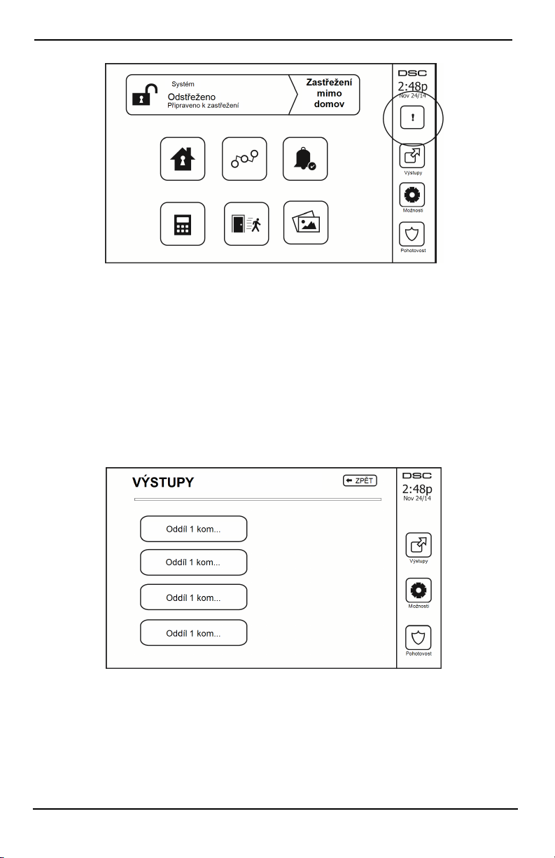
Problémy
Obrázek 5– Alarmy vpaměti
Resetování senzorů
Některé senzory po zjištění stavu alarmu vyžadují pro ukončení stavu alarmu resetování (např. senzory tříštění
skla, detektory kouře atd.). Zeptejte se uspolečnosti zajišťující služby alarmu, zda je tato funkce
vsystému vyžadována.
Chcete-li detektory resetovat, stiskněte tlačítko Reset (příkazový výstup 2, pokud instalátor nenaprogramoval
označení) na obrazovce Výstupy. Pokud se senzor neresetuje, může stále zjišťovat stav alarmu. Pokud je resetování
senzoru úspěšné, alarm se zruší. Pokud je neúspěšné, alarm se opět aktivuje nebo pokračuje.
Výstupy
Instalační technik mohl tato tlačítka naprogramovat na provádění různých funkcí (resetování detektoru kouře po
alarmu, otevření garážových vrat atd.). Chcete-li tyto funkce aktivovat, stiskněte Výstup a potom stiskněte
příslušnou možnost. Další informace naleznete v části: Resetování senzorů.
Obrázek 6– Výstupy
- 15 -
Page 50

Dodatečné funkce
Dodatečné funkce
Fotografie
Můžete vytvořit prezentaci zfotografií azobrazovat ji na klávesnici. Fotografie jsou přidávány pomocí karty SD
(32 × 24 × 2,1mm. Není součástí balení).
Fotografie musí být ve formátu .jpg amohou mít velikost až 1280 × 720. Pro dosažení nejlepších výsledků
použijte rozlišení 800 × 480. Pomocí softwaru pro úpravu fotografií upravte veli kost fotografií.
Chcete-li zahájit prezentaci, nastavte spořič obrazovky na režim fot ografií. Prezentace se přehrává automaticky,
dokud není dosažen časový limit, nebo dokud se znovu nedotknete obrazovky.
Chcete-li přidat fotografie:
1. Stiskněte tlačítko Možnosti, Uživatelské funkce, Konfigurace klávesnice, Fotorámeček, Výběr fotografií. Zobrazí
se miniatury fotografií na kartě SD.
2. Klepnutím na obrázek j ej přidáte do prezentace. Druhým klepnutím jej odstraníte.
Pomocí posuvníku Čas přechodu naprogramujte dobu, po kterou je každá fotografie zobrazena na obrazovce, od
5sekund do 1minuty.
Pomocí posuvníku Časový limit fotorámečku můžete řídit, jak dlouho se bude prezentace přehrávat, od 1minuty
do 2hodin. Zvolte Nikdy, chcete-li prezentaci nechat přehrávat, dokud se nedotknete obrazovky.
Poznámka: Je podporováno maximálně 255 fotografií.
Rychlý odchod
Pokud je syst ém aktivován amusíte místo opustit, použijte funkci rychlého odchodu, aby nedošlo kdeaktivaci
aopětné aktivaci systému. Chcete-li tut o funkci aktivovat, klepněte na ikonu Rychlý odchod. Máte 2 minuty na to,
abyste opustili prostory dveřmi pro odchod. Po opětovném zavření dveří se zbývající doba pro odchod zruší.
Programování času adata
Klepněte na tlačítko Možnosti. Zvolte Uživatelské funkce [hlavní kód] apoté zvolte Čas adatum. Klepněte na
část, kterou chcete změnit, a pomocí šipek nahoru/dolů změňte čas/datum. Po dokončení stiskněte tlačítko Uložit.
Režim klávesnice
Tato možnost umožňuje dotykové obrazovce HS2TCHPRO/HS2TCHPROBLK fungovat jako t radiční klávesnice
DSC.
Dveřní zvonek (povolení/zakázání zvonku)
Klávesnice signalizuje aktuální stav funkce dveřního zvonku (povoleno nebo zakázáno). Chcete-li zvolit opačnou
funkci, klepněte na ikonu „Zvonek“. Tři pípnutí signalizují, že zvonek je zapnutý (povolen). Jedno dlouhé pípnutí
signalizuje, že zvonek je vypnutý (zakázán).
Poznámka: Funkce dveřního zvonku by se měla používat pouze vrežimu Střežení deaktivováno.
Vynechání zóny
Tato obrazovka umožňuje zobrazit stav zón vsystému.
- 16 -
Page 51
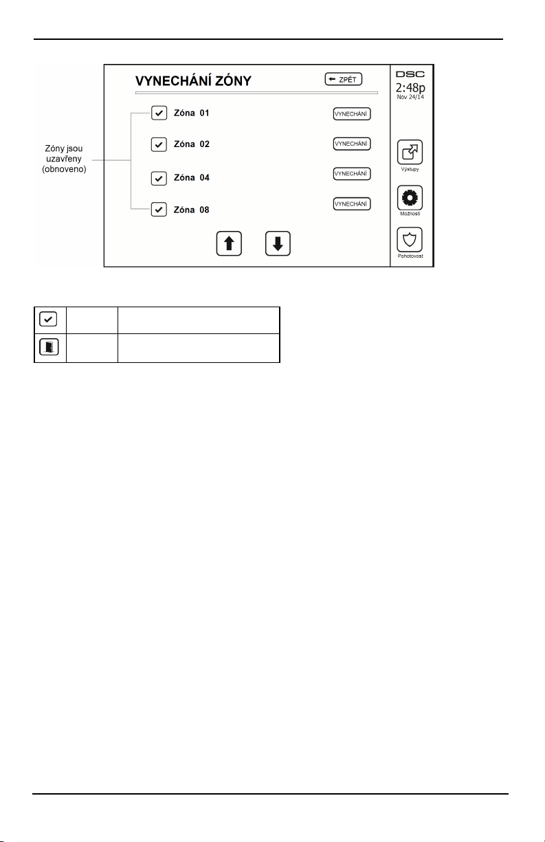
Nabídka možnosti
Obrázek 7– Zóna uzavřena
Kontrolky stavu zóny
Připravena Zóna je uzavřena
Otevřená Zóna je otevřená amusí být uzavřena
Vynechané zóny
Pokud je zóna otevřená, ale systém musí být aktivován, použijte funkci vynechání zóny. Vynechané zóny nebudou
při otevření generovat alarm. Vynechávání zón snižuje úroveň zabezpečení. Pokud vynecháváte zónu, protože
nefunguje, zavolejte neprodleně servisního technika, aby se problém vyřešil asystém se vrátil do správného
provozního stavu.
Ověřte, že při aktivaci systému nebyly neúmyslně vynechány žádné zóny. Vynechání zóny může být provedeno
pouze tehdy, když je systém deaktivován. Vynechané zóny jsou automaticky zrušeny při každé deaktivaci systému
apřed další aktivací musí být znovu vynechány, pokud je to nezbytné.
Poznámka: 24hodinové zóny lze vynechat pouze ručně.
Poznámka: Z bezpečnostních důvodů instalátor naprogramoval systém, aby zabránil vynechání některých zón.
(Např. detektory kouře).
Vynechávání zón se zařízením HS2TCHPRO/HS2TCHPROBLK
Když se nacházíte na stránce Stav zóny, přejděte nahoru/dolů po požadovaných zónách aklepnutím na ikonu
vynechání proveďte vynechání zóny. Chcete-li zrušit vynechání zóny, klepněte na ikonu zrušit vynechání.
Poznámka: U i nstalací s certifikací UL mohou být zóny vynechány pouze ručně.
Nabídka možnosti
Stisknutím tlačítka Možnosti na pravé straně domovské stránky získáte přístup knásledujícím funkcím. Více
informací naleznete v on-line uživatelské příručce zařízení HS2TCHPRO/HS2TCHPROBLK.
l Přístupové kódy
l Nabídka instalátora
l Uživatelské funkce
l Zvonek povolen/zakázán
l Stav oddílů
l Režim klávesnice
- 17 -
Page 52

Nabídka možnosti
Obrázek 8– Možnosti
Přístupové kódy
Pokud jsou vnabídce Možnosti vybrány Přístupové kódy, klávesnice vyzve k zadání hlavního kódu. Po zadání
platného hlavního kódu se zobrazí číselná klávesnice sšipkami pro procházení seznamu uživatelů. Stisknutím
tlačítka Vybrat vyberte možnosti uživatele.
Nastavit přístupový kód: přidání/úprava 4ciferného nebo 6ciferného kódu
Nastavit oddíly: přiřazení uživatele k oddílům
Možnosti uživatele: povolení/zakázání různých možností pro uživatele
Odstranit uživatele: odstranění uživatele ze syst ému
Přístupové kódy mají programovatelné atributy, které umožňují vynechání zón nebo aktivaci jednorázového
použití.
Hlavní kód (přístupový kód 01): hlavní kód, pokud je naprogramován, může změnit pouze instalační technik.
Kódy správce: Tyto kódy l ze použít knaprogramování dalších kódů, které mají stejné nebo nižší atributy. Po
naprogramování získávají kódy správce atributy hlavního kódu. Tyto atributy lze měnit. Jakýkoli uživatelský kód
může být učiněn kódem správce povolením atributu uživatelského kódu 1 (podrobnosti jsou uvedeny níže).
Tísňové kódy: Tísňové kódy jsou standardními uživatelskými kódy, které při zadávání pro vykonání jakékoli
funkce vsystému přenášejí kód pro hlášení tísně. Jakýkoli uživatelský kód může být učiněn tísňovým kódem
povolením atributu uživatelského kódu 2 (podrobnosti jsou uvedeny níže).
Poznámka: Tísňové kódy nejsou platné při přecházení do částí Programování uživatele, Hlavní funkce nebo
Instalátor.
Poznámka: Přístupové kódy nelze naprogramovat jako duplikát nebo j ako „kód +/- 1“.
Přiřazení bezkontaktních čipů
V závislosti na tom, jak je klávesnice naprogramována, mohou být bezkontaktní čipy použity buď
kaktivaci/deaktivaci střežení systému, nebo kprovádění naprogramované funkce (např. odemknutí skříně nebo
dveří skladu). Přiložte čip ke čtečce čipů.
1. Stiskněte [*][5] hlavní kód / kód správce].
2. Zadejte 4místný nebo 6místný uživatelský kód.
3. Stiskněte tlačítko 2.
4. Přiložte přihlášený čip do blízkosti čtečky čipů.
- 18 -
Page 53

Nabídka možnosti
Odebrání bezkontaktních čipů
Chcece-li odebrat bezkontaktní čipy:
1. Zvolte Možnosti, Přístupové kódy [zadejte hl avní kód].
2. Vyberte uživatele, kterého chcete odstranit.
3. Zvolte možnost Prog bezkont. čipu a poté jej odstraňte.
Atributy uživatelských kódů
1. Výchozími atributy nového kódu budou atributy kódu používaného pro vstup do části Programování
uživatele, ať už se jedná oprogramování nového kódu nebo stávajícího kódu.
2. Hlavní kód systému 01 má ve výchozím nastavení přístup koddílům pro všechny oddíly arovněž
zapnuté atributy 3–4.
Poznámka: Tyto atributy nelze měnit .
Základní atributy (všechny kódy kromě instalátora aúdržby)
Aktivace/deaktivace střežení: Jakýkoli přístupový kód spovoleným přístupem k oddílu bude platný pro
aktivaci adeaktivaci daného oddílu.
Výstupy příkazů ([*][7][1], [*][7][2], [*][7][3] a [*][7][4]): Pokud tyto výstupy vyžadují zadání
přístupového kódu, bude jakýkoli přístupový kód spřístupem k oddílu platný pro provádění funkcí výstupů
příkazů v rámci daného oddí lu.
Programovatelné atributy
1. Kód správce 5. Pro bud. použití
2. Tísňový kód 6. Pro bud. použití
3. Vynechání zón povoleno 7. Zvukový signál zvonku po aktivaci/deaktivaci střežení
4. Vzdálený přístup 8. Jednorázový uživatelský kód
Atribut zvukového signálu zvonku
Tento atribut slouží kurčení, zda má přístupový kód generovat zvukový signál zvonku při aktivaci/deaktivaci
střežení po zadání kódu pro aktivaci Pryč. Bezdrátové klíče spřístupovými kódy, které jsou snimi spojeny,
mohou generovat zvukové signalizace aktivace/deaktivace střežení. Pokud je to požadováno, tato možnost může
být použita ukódů, které j sou zadávány ručně. Chcete-li naprogramovat tuto funkci, obraťte se na instalátora.
Poznámka: Hlavní kód nemůže používat atribut zvukového signálu zvonku, ale je vyžadován kpovolení tohoto
atributu uostatních kódů.
Poznámka: Tato funkce nemůže zamezit generování zvukového signálu při aktivaci/deakti vaci střežení, pokud je
přístupový kód přiřazený kbezdrátovému klíči zadán ručně na klávesnici.
Poznámka: Tato funkce se používá pro hlášení signálů oproblému požáru a také problémových podmínek pro
zdravotní aplikace.
Přiřazení oddílu
1. Tato část se používá k přiřazení uživatelů kdostupným oddílům. Chcete-li přiřadit oddíly:
2. Zvolte Možnosti > Přístupové kódy.
3. Zadejte hlavní kód.
4. Vyberte uživatele.
5. Zvolte Atributy oddílů.
6. Vyberte oddíl(y), který(-é) chcete přiřadit uživateli.
Poznámky kpřístupovým kódům aprogramování
l Atributy hlavní ho kódu nelze změnit.
l Při naprogramování nového kódu vProgramování uživatele se provede kontrola všech ostatních kódů
vsystému. Pokud je nalezen dupli citní kód, zazní chybový tón akód se vrátí do stavu, ve kterém byl
před změnou. To platí pro 4místné a6místné kódy.
- 19 -
Page 54

Nabídka možnosti
Vymazání přístupového kódu
Chcete-li kód smazat, vyberte kód azvolte Odstranit uživatele. Systém okamžitě odstraní kód auživatel bude
navrácen kvolbě jiného kódu.
Nabídka instalátora
Tyto funkce jsou určeny pouze pro potřeby i nstalátora.
Uživatelské funkce
Nejprve deaktivujt e systém apoté zadejte Možnosti, Uživatelské funkce apoté hlavní kód. Tento příkaz slouží
kzískání přístupu knásledujícímu seznamu hlavních funkcí systému:
Datum a čas
Zadejte požadovaný čas a datum.
Čas automatické aktivace
Systém může být naprogramován tak, aby se aktivoval vnaprogramovaném čase každý den podle oddílů. Po
přechodu do této části zadejte požadovaný čas automatické aktivace pro každý den vtýdnu.
Ve zvoleném čase automatické aktivace budou bzučáky klávesnice znít po naprogramovanou dobu (může
naprogramovat pouze instalátor) pro upozornění, že probíhá automatická aktivace. Zvonek může být rovněž
naprogramován t ak, aby během této doby upozornění každých 10 sekund vydával zvukový signál. Po uplynutí
doby upozornění se systém aktivuje bez prodlevy odchodu av režimu Pryč.
Automatickou aktivaci lze zrušit nebo odložit zadáním platného přístupového kódu pouze během naprogramované
doby upozornění. K pokusu oautomatickou aktivaci dojde následující den ve stejnou dobu. Když je proces
automatické aktivace zrušen nebo odložen, bude přenášen kód hlášení ozrušení automatické aktivace (pokud je
naprogramován).
Přenos zrušení automatické aktivace bude předán, pokud je aktivace potlačena některým znásledujících způsobů:
l Inhibice aktivace střežení AC/DC
l Blokující manipulace se systémem
l Porucha správy expandéru zóny
Poznámka: U i nstalací s certifikací UL/ULC musí být funkce automatické aktivace zrušena, jestliže jsou zóny
vmimořádném stavu.
Povolit DLS / Povolit systémovou službu
Je-li tato možnost povolena, instalátor bude mít přístup kprogramování instalátora prostřednictvím vzdáleného
přístupu (DLS). Okno DLS zůstane otevřeno po dobu 6hodin, během které bude mít instalátor neomezený přístup
do DLS. Po uplynutí 6hodinového okna bude programování instalátora opět nedostupné, dokud nebude okno
znovu otevřeno.
Paměť událostí
l Zobrazuje datum, čas a úplný popis události
l Protokol je řazen od nejnovější události (nahoře) po události minulé (dole)
l Pomocí šipky Vlevo lze posouvat dopředu včase
l Pomocí šipky Vpravo lze posouvat zpět v čase
l Tlačítko Zpět vás vrátí na domovskou obrazovku
l Po 30 sekundách nečinnosti vyprší časový limit této obrazovky azobrazí se domovská obrazovka
Systémový test
Jsou zkoušeny výstup zvonku systému, kontrolky klávesnice akomunikátor. Tento test také změří kapacitu
záložní baterie ústředny.
Důležité:
- 20 -
Page 55

Nabídka možnosti
l Chcete-li ověřit, že systém nadále pracuje zamýšleným způsobem, je zapotřebí jej jednou týdně zkoušet.
l U aplikací scertifikací UL HOME HEALTH CARE (UL domácí zdravotní péče) musí být systém
rovněž testován jednou týdně bez napájení střídavým proudem. Chcete-li odpojit napájení střídavým
proudem od řídicí jednotky, odstraňte šroub ze zajišťovací zarážky zástřčkového adaptéru aodpojte
adaptér ze síťové zásuvky. Po dokončení testu jednotky pouze za použití zdroje záložní baterie znovu
připojte zástrčkový adaptér aupevněte šroub přes zajišťovací zarážku tak, aby byl adaptér bezpečně
připojen kzásuvce.
l Pokud systém nefunguje správně, neprodleně kontaktujte instalátora.
l Všechny detektory kouře musí být jednou ročně testovány instalátorem pro zajišt ění řádného provozu.
Ovládání automatické aktivace/deaktivace střežení
Stisknutím tlačítka Automatická aktivace vnabídce Uživatelské funkce povolíte (tři pípnutí) nebo zakážete (jedno
dlouhé pípnutí) funkci automatické aktivace aautomati cké deaktivace podle oddílu. Pokud je tato funkce zapnuta,
ústředna se automaticky aktivuje v režimu Pryč (aktivní zóny aktivace v režimu Pobyt / aktivace v režimu Pryč)
nebo se deaktivuje každý den ve stejnou dobu. Čas aut omatické aktivace se programuje tlačítkem Čas automati cké
aktivace. Automatická aktivace musí být naprogramována instalátorem systému.
Vyvolání uživatele
Tato volba poskytuje provozovateli služeb dočasný přístup kzabezpečovací ústředně pro vzdálený servis.
Inženýrský reset
Pokud se vsystému vyskytl alarm, systém nedovolí opětovnou aktivaci (kontrolka Připraveno nesvítí). Bude
nutné kontaktovat instalátora. Provedou kontrolu a resetují systém za vás. Může to zahrnovat návštěvu pro
kontrolu systému. Po provedení resetování bude systém opět fungovat správně.
Konfigurace klávesnice
Obrázek 9– Konfigurace klávesnice
Možnosti displeje: nastavení jasu ačasového limitu dotykové obrazovky a rovněž možností spořiče obrazovky.
Ovládání bzučáku: nastavení hlasitosti bzučáku dotykové obrazovky. Poznámka: Vpřípadě SIA CP-01 nesmí
být hlasitost bzučáku nastavena na minimální hodnotu.
Poznámka: U i nstalací s certifikací UL/ULC se úroveň bzučáku nesmí měnit zvýchozí úrovně.
Fotorámeček: výběr obrázků, které budou zobrazeny v prezentaci.
Kalibrace: kalibrace dotykové obrazovky.
Režim hodin: zobrazení digitálních hodin.
Režim čištění: umožňuje uživateli dotknout se obrazovky (za účelem čišt ění) bez povolení nebo zakázání
jakýchkoli funkcí. Obrazovka vtomto režimu zůstane po dobu 30sekund, poté se vrátí na obrazovku Konfigurace
klávesnice.
- 21 -
Page 56

Nabídka možnosti
Obrázek 10– Režim čištění
Domovská stránka: lze nakonfigurovat vjednom ze dvou různých vzhledů, klasický (čtvercová tlačítka)
amoderní (oblá).
Zvonek povolen/zakázán
Dveřní zvonek: Chcete-li zapnout nebo vypnout funkci dveřního zvonku, klepněte na ikonu Zvonek. 3 pípnutí
signalizují, že zvonek je zapnutý. 1 dlouhé pípnutí signalizuje, že zvonek je vypnutý.
Střežení
Aktivace v režimu Pobyt: aktivuje systém vrežimu Pobyt
Aktivace v režimu Pryč: aktivuje systém vrežimu Pryč
Noční aktivace: Chcete-li plně aktivovat systém, když byl aktivován v režimu Pobyt, stiskněte tlačítko Noční
aktivace. Všechny zóny interiéru budou nyní aktivovány, kromě zařízení naprogramovaných jako noční zóny.
Noční zóny jsou aktivovány pouze vrežimu Pryč. To umožňuje omezený pohyb vprostorách, když je systém plně
aktivován. Ověřte, že vám instalátor poskytl seznam s uvedením 18 zón naprogramovaných jako noční zóny.
Chcete-li získat přístup do oblastí interiéru, které nebyly naprogramovány jako noční zóny, když byly zóny
interiéru aktivovány (tj. Noční aktivace), musíte zadat přístupový kód pro deaktivaci systému.
Rychlý odchod: viz část: Rychlý odchod
Globální aktivacev režimu Pryč: aktivuje všechny oddíly, k nimž je přiřazen uživatelský kód, v režimu Pryč.
Globální aktivace v režimu Pobyt: aktivuje všechny oddíly, k nimž je přiřazen uživatelský kód, v režimu
Pobyt.
Aktivace vrežimu Vstup zakázán: aktivuje systém v režimu zakázaného vstupu.
Stav oddílů
Chcete-li zobrazit stav oddílů, stiskněte tlačítko Možnosti, Uživatelské funkce aStav oddílů. Klávesnice zobrazuje
základní stav až pro 8 oddílů vzávislosti na konfiguraci systému. Je uveden každý oddíl spolu se svým aktuálním
stavem.
- 22 -
Page 57
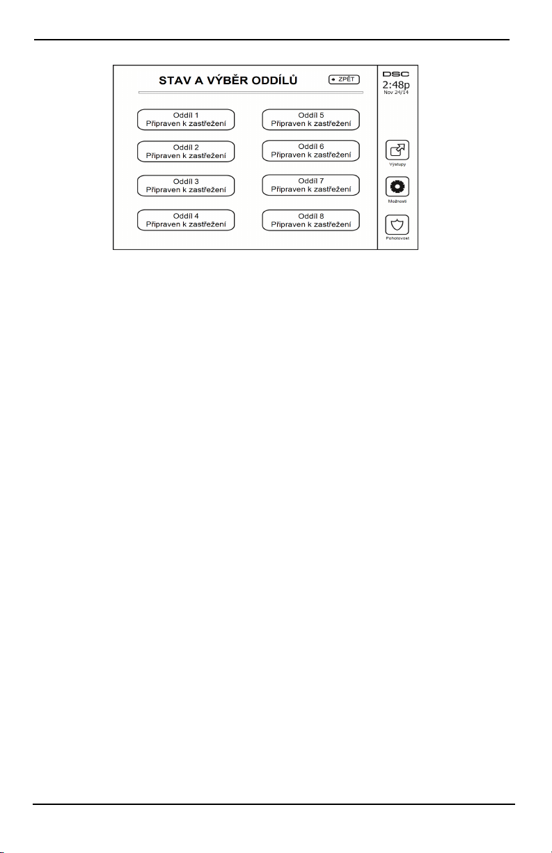
Správa oddílů
Obrázek 11– Stav oddílů
Režim klávesnice
Tato možnost umožňuje dotykové obrazovce HS2TCHPRO/HS2TCHPROBLK fungovat jako t radiční klávesnice
DSC.
Správa oddílů
Oddíl je omezenou oblastí prostor, která funguje nezávisle na ostatních oblastech. Rozdělení systému na oddíly
může být prospěšné, pokud prostory obsahují přístavby, které je třeba zabezpečit nezávisle na hlavní oblasti nebo
pokud domácnost obsahuje samostatný byt. Každý oddíl může mít svou vlastní klávesnici nebo může mít
klávesnice přístup ke všem oddílům. Přístup uživatele koddílům je řízen pomocí přístupového kódu. Hlavní kód
může přistupovat kcelému systému a všem oddílům, zatímco uživatelský kód je omezen na přiřazené oddíly.
Oddíly
Klávesnice lze nakonfigurovat kovládání indivi duálního oddílu nebo všech oddílů.
Poznámka: Přístup ktéto funkci musí nakonfigurovat instalátor.
Provoz jednoho oddílu
Klávesnice sjedním oddílem poskytují přístup kfunkcím alarmu pro přiřazený oddíl.
Klávesnice sjedním oddílem pracují následujícím způsobem:
l Zobrazuje stav střežení aktivováno nastaveno oddílu.
l Zobrazují otevřené zóny, pokud je zapnuto přiřazení klávesnice koddílu.
l Zobrazuje vynechané zóny aumožňuje vynechání zón nebo vytváření skupin vynechání zón přiřazených
koddílům klávesnice.
l Zobrazuje problémy se systémem (vybití baterie systému, poruchy systémových komponent /
neoprávněná manipulace s nimi).
l Zobrazuje vpaměti alarmy, které se vyskytly voddílu.
l Umožňuj í aktivaci/deaktivaci zvonku dveří.
l Test systému (aktivuje zvonky / PGM přiřazené k oddílu).
l Programování označení (označení zóny, oddílu a uživatelská označení pro oddíl).
l Ovládací příkazové výstupy (výstupy přiřazené k oddílu nebo globální výstupy, např. resetování
detektoru kouře).
l Teploty.
Zapůjčení klávesnice jinému oddílu
Klávesnice sdotykovou obrazovkou HS2TCHP může být zapůjčena pro provoz s jinými oddíly. Když je
klávesnice zapůjčena jinému oddílu, pracuje na zapůjčeném oddílu, jako kdyby k němu byla původně přiřazena.
Před zapůjčením klávesnice jinému oddílu musí být zadán přístupový kód. Přístupový kód je rovněž vyžadován
kprovedení jakékoli funkce vdaném oddílu.
- 23 -
Page 58

Správa oddílů
Chcete-li zapůjčit klávesnici jinému oddílu:
1. Zvolte Možnosti > Stav oddílů.
2. Zadejte přístupový kód.
3. Vyberte oddíl, kterému chcete klávesnici zapůjčit. Pokud je klávesnice neaktivní po dobu delší než
30 sekund, vrátí se do původní ho oddílu.
Provoz globální klávesnice
Jakmile je zadán platný přístupový kód, globální klávesnice zobrazí stav všech oddílů, ukterých má uživatel
oprávnění kzobrazení. Z tohoto přehledu můžete zapůjčit globální klávesnici do oddílů, aktivovat všechny oddíly
nebo deaktivovat všechny oddíly. Stav jednotlivých oddílů udává ikona stavu oddílu. Vysvětlení ikon stavu
oddílu naleznete vnásledující tabul ce. Tlačítka pro globální aktivaci aglobální deaktivaci aktivují nebo
deaktivují všechny zobrazené oddíly.
Chcete-li zapůjčit globální klávesnici jinému oddílu:
1. Zvolte Stav oddílů.
2. Vyberte oddíl, kterému chcete klávesnici zapůjčit.
Obrázek 12– Režim globální klávesnice
Oddíl
Ikona stavu
Popis
ZELENÉ POZADÍ
Oddíl je připraven kaktivaci
Oddíl je ve stavu zpoždění při odchodu
ŠEDÉ POZADÍ
Oddíl není připraven kaktivaci
Oddíl je ve stavu alarmu
Oddíl je ve stavu zpoždění při vstupu
Oddíl je aktivován
- 24 -
Page 59

Správa oddílů
Typy požárních aCO zón
l Pokud požární zóna generuje alarm, do alarmu přejde pouze oddíl, ke kterému je požární zóna přiřazena.
Ostatní oddíly zachovávají svůj aktuální stav.
l Pokud je ke generování alarmu použito tlačítko [F] na globální klávesnici, všechny povolené oddíly
přejdou do alarmu.
l V jakémkoli oddí lu lze umístit jednu nebo více klávesnic.
l Při alarmu se na všech klávesnicích oddílu ana všech globálních klávesnicích zobrazí hlášení opožáru
sautomatickým posouváním. Přímo na libovolné klávesnici oddílu lze provést utišení požárního alarmu
a reset požárního systému. Aby bylo možné zglobální klávesnice utišit požární nebo CO alarm, je třeba,
aby byla globální klávesnice dočasně připojena kjednomu zoddíl ů.
- 25 -
Page 60

Testování systému
Testování systému
Poznámka: Pokud budete provádět test systému, telefonicky kontaktujte moni torovací stanici, abyste její
pracovníky informovali, kdy test zahájíte akdy jej ukončíte.
Testování bzučáku klávesnice asirény
Test systému provede dvousekundovou kont rolu bzučáku klávesnice a zvonku nebo sirény adále testování
kontrolek stavu klávesnice azáložní baterie ústředny.
1. Stiskněte tlačítko Možnosti, Uživatelské funkce [Hlavní kód] apoté Test systému. Dojde knásledujícím
událostem:
- Systém po dobu 2sekund aktivuje všechny bzučáky klávesnic azvonky nebo sirény. Všechny
kontrolky klávesnice se rozsvítí.
- Po dobu trvání testu budou blikat kontrolky LED Připraveno, Střežení aktivováno aProblém.
2. Chcete-li opustit nabídku funkcí, stiskněte tlačítko [#].
Testování celého systému
Všechny detektory kouře vtéto instalaci musí být jednou ročně testovány instalátorem či prodejcem pro ověření,
že fungují správně. Uživatel odpovídá za to, že bude testovat systém jednou týdně (kromě detektorů kouře). Dbejte
na to, abyste postupovali podle všech kroků včásti „Zkoušení bzučáku klávesnice asirény“.
Poznámka: Pokud systém nefunguje správně, neprodleně zavolejte instalátora pro provedení servisu.
1. Před testováním se ujistěte, že je systém deakti vován akontrolka Připraveno svítí.
2. Chcete-li uvést systém do stavu Připraveno, uzavřete všechny zóny.
3. Proveďte test systému tak, že budete postupovat podle všech kroků včásti „Testování bzučáku
klávesnice asirény“.
4. Chcete-li zkontrolovat zóny, aktivujte post upně každý detektor (např. otevřete jednotlivé dveře/okna
nebo projděte oblasti detektoru pohybu).
Na klávesnici zařízení HS2TCHPRO/HS2TCHPROBLK budou v případě aktivace jednotlivých (detektorů)
zón zobrazeny následující zprávy: „Připraveno k vynucení“, „Nepřipraveno“. Pomocí tlačítka stavu zóny zobrazíte,
které zóny jsou otevřené. Po uzavření zón zpráva zmizí.
Poznámka: Některé funkce popsané výše nebudou funkční, pokud je instalátor nepovolí. Zeptejte se instalátora,
které funkce jsou vsystému funkční .
Režim zkoušení průchodu
Instalalátor může usystému spustit režim zkoušení průchodu. V režimu zkoušení průchodu budou blikat
kontrolky LED Připraveno, Střežení akt ivováno a Problém, což signalizuj e, že je testování průchodu aktivní. Když
systém automaticky ukončí režim zkoušení průchodu, ohlásí to slyšitelným varováním (5pípnutí každých
10 sekund), počínaje pěti minutami před ukončením zkoušky.
Umožnění přístupu počítače ksystému
Čas od času může instalátor zaslat informace do bezpečnostního systému nebo je zněj získat. Instalátor to provede
tak, že prostřednictvím počítače zavolá systém přes telefonní linku. Možná bude nezbytné systém na tento
„stahovací“ hovor připravit. Chcete-li to provést, stiskněte tlačítko Možnosti, Uživatelské funkce [Hlavní kód]
apoté Systém. sl./DLS na dotykové obrazovce. Tent o postup umožňuj e na omezenou dobu stahování. Během této
doby bude systém odpovídat na příchozí stahovací hovory. Další informace o této funkci získáte od instalátora.
- 26 -
Page 61

Referenční listy
Referenční listy
Následující informace vyplňte pro budoucí použití a tuto příručku uložte na bezpečném místě.
Informace o systému Povoleno?
[F] POŽÁR [+] Zdravotní [P] NOUZE
Čas prodlevy odchodu je ___ sekund
Čas prodlevy příchodu je ___ sekund
Pro účely servisu
Informace ohlavní stanici:
Účet: ________________ Telefon: ________________
Informace o osobě provádějící instalaci:
Společnost: ________________ Telefon: ________________
Datum instalace/servisu baterie:
__________________________
__________________________
__________________________
Pokud máte podezření, že byl na centrální monitorovací stanici odeslán signál falešného alarmu, stanici
zavolejte, abyste zabránili zbytečné odezvě.
- 27 -
Page 62

Přístupové kódy (kopírujte podle potřeby)
HS3032/HS3128/HS3248 HLAVNÍ KÓD [01]: ________________________
Uživatelská Přístupový kód Uživatelská Přístupový kód Uživatelská
01 35 69
02 36 70
03 37 71
04 38 72
05 39 73
06 40 74
07 41 75
08 42 76
09 43 77
10 44 78
11 45 79
12 46 80
13 47 81
14 48 82
15 49 83
16 50 84
17 51 85
18 52 86
19 53 87
20 54 88
21 55 89
22 56 90
23 57 91
24 58 92
25 59 93
26 60 94
27 61 95
28 62 96
29 63 97
30 64 98
31 65 99
32 66 100
33 67
34 68
Referenční listy
- 28 -
Page 63

Referenční listy
Informace osenzoru/zóně (kopírujte podle potřeby)
Zóně Chráněná oblast Typ senzoru
1
2
3
4
5
6
7
8
9
10
11
12
13
14
15
16
17
18
19
20
21
22
23
24
25
26
27
28
29
30
- 29 -
Page 64

Pokyny pro umisťování detektorů kouře adetektorů CO
Pokyny pro umisťování detektorů kouře adetektorů
CO
Následující informace jsou pouze obecné pokyny a doporučuje se, aby se při lokalizaci a instalaci kouřových a CO
hlásičů konzul tovali místní požární kódy a předpisy.
Detektory kouře
Průzkumy ukazují, že všechny nežádoucí požáry v budovách do větší či menší míry vytvářejí kouř. Experimenty s
typickými požáry v domech naznačují, že ve větši ně případů detekovatelné množství kouře předchází
detekovatelnému množství tepla. Z těchto důvodů by měly být kouřové hlásiče instalovány vně každé oblasti pro
spaní a na každém patře domu. Následující informace jsou pouze obecné pokyny a doporučuje se, aby se při
lokalizaci a instalaci kouřových hlásičů konzultovali místní požární kódy a předpisy. Doporučuje se, aby byla
nainstalována také další kouřová alarmová zařízení anikoli pouze ta, která jsou nutná pro minimální ochranu.
Mezi další oblasti, které by měly být chráněny, patří: sklepy; ložnice, zejména pokud v nich spí kuřáci; jídelny;
místnosti s kotlem a technické místnosti; a jakékoli chodby, které nejsou chráněny požadovanými jednotkami. Na
hladké stropy lze detektory rozmísťovat nejvýhodněji vrozmezí po 9,1 m (30 stop) od sebe. Jiné rozestupy mohou
být vyžadovány v závislost i na výšce stropu, pohybu vzduchu, přítomnosti trámů, neizolovaných stropů apod.
Doporučení k instalaci naleznete vnárodním kodexu pro požární alarmy NFPA 72, CAN/ULC-S553-02 nebo
vostatních příslušných národních normách.
l Detektory kouře neinstalujte do horní části štítu nebo průčelí stropů; mrtvý vzdušný prostor vtěchto
místech může zabránit tomu, aby jednotka detekovala kouř.
l Vyhněte se místům srozvířeným vzduchem, například vblízkosti dveří, ventilátorů nebo oken. Rychlé
vzdušné proudění vokolí detektoru může zabránit průniku kouře do přístroje.
l Detektory neumisťujte v místech svysokou vlhkostí.
l Neumisťujte detektory do oblastí, ve kterých teplota stoupá nad 38°C nebo klesá pod 5°C.
V USA by detektory kouře měly být vždy instalovány vsouladu skapitolou 29 dokumentu NFPA 72, National
Fire Alarm Code: 29.5.1.1.
Pokud to pro konkrétní druh obydlí vyžaduje jiné rozhodné právo, kodexy nebo normy, musí být instalovány
schválené kouřové alarmy sjednou a více stanicemi následujícím způsobem:
1. Do všech ložnic a přijímacích pokojů.
2. Vně každého samostatného prostoru pro spaní vobytné jednotce, do vzdálenosti 6,4m od jakýchkoli
dveří do ložnice, přičemž vzdálenost se měří podél trasy cesty.
3. Na každé úrovni bytové jednotky včetně sklepů.
4. Na každé úrovni obyt ného bloku a obsazenosti péče (malé zařízení), včetně sklepů a bez výklenků a
nedokončených podkroví.
5. Do obytných prost orů ubytovací lóže.
6. Do obytných prost orů obytného ubytovacího a pečovatelského zařízení (malý podnik).
- 30 -
Page 65
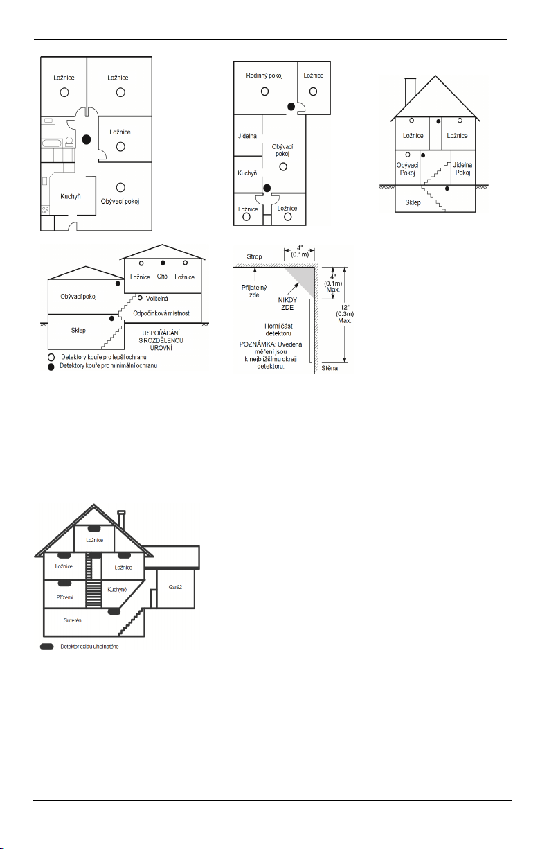
Pokyny pro umisťování detektorů kouře adetektorů CO
Detektory oxidu uhelnatého
Oxid uhelnatý je bezbarvý, bez zápachu, bez chuti avelmi toxi cký. Rovněž se volně pohybuje ve vzduchu.
Detektory CO jsou schopné měřit koncentraci a před dosažením potenciálně škodlivé úrovně vydávat hlasitý
alarm. Lidské tělo je nejvíce ohroženo působením CO během spánku; proto by detektory CO měly být umístěny
voblasti pro spaní nebo co nejblíže v domácnosti. Pro maximální ochranu by měl být alarm CO umístěn vně
hlavních prostor pro spaní nebo na každé úrovni domácnosti. Obrázek 5 ukazuje doporučená umístění
vdomácnosti.
Alarm CO NEUMISŤUJTE do následujících oblastí:
l Kde může teplota klesnout pod −10°C nebo překročit 40 °C
l Poblíž výparů rozpouštědel
l Blíže než 5 stop (1,5m) od spotřebičů s otevřeným ohněm, jako jsou například pece, kamna a ohniště.
l Do proudu výfukových plynů z plynových motorů, větracích otvorů, kouřovodů nebo komínů
l Neumísťujte detektor do těsné blízkosti výfukové trubice automobilu. Tím se detektor poškodí.
- 31 -
Page 66

Pokyny pro umisťování detektorů kouře adetektorů CO
BEZPEČNOSTNÍ POKYNY A INFORMACE PRO HAVARIJNÍ SITUACE NAJDETE V PŘÍRUČCE S
NÁVODEM KINSTALACI A PROVOZU DETEKTORU OXIDU UHELNATÉHO (CO).
Audit požární bezpečnosti domů
V této části j dou uvedeny důležité informace o požární bezpečnosti. K většině požárů dochází vdomácnosti. Pro
minimalizaci tohoto nebezpečí doporučujeme provádět kontrolu požární bezpečnosti domů avypracovat požární
únikový plán.
1. Jsou všechny elektrické přístroje azásuvky vbezpečném stavu? Zkontrolujte roztřepené kabely,
přetížené obvody osvětlení atd. Pokud nemáte jistotu ohledně stavu elektrických přístrojů nebo
domácích zařízení, nechte tyto jednotky odborně vyhodnotit.
2. Jsou všechny hořlavé kapaliny bezpečně skladovány vuzavřených nádobách na dobře větraném
chladném místě? Je třeba se vyvarovat čištění pomocí hořlavých kapalin.
3. Jsou materiály snebezpečím požáru (např. zápalky) mimo dosah dětí?
4. Jsou kotle azařízení na spalování dřeva správně instalovány, čisté av dobrém stavu? Nechte tyto
jednotky odborně vyhodnotit.
Plánování požárních únikových cest
Mezi detekcí požáru a dobou, kdy se požár stává smrtelným nebezpečím, je často velmi krátká doba. Je proto velmi
důležité, abyste vypracovali a nazkoušeli únikový plán rodiny.
1. Na vypracování únikového plánu by se měl podílet každý člen rodiny.
2. Prozkoumejte možné únikové cesty ze všech míst vdomě. Protože kmnoha požárům dochází vnoci, je
třeba přikládat obzvláštní pozornost únikovým cestám zmíst spánku.
3. Únik zložnic musí být možný bez otevření vnitřních dveří.
Při plánování únikových cest uvažte následující:
l Ujistěte se, že lze všechny okrajové dveře a okna snadno otevřít. Ujistěte se, že jejich otevření není
znemožněno nátěrem a že řádně fungují jejich zamykací mechanismy.
l Je-li otevření nebo použití východu pro děti, starší nebo zdravotně post ižené příliš těžké, měly by být
vypracovány plány na záchranu. Sem patří zajištění, aby ti, kdo budou provádět záchranné práce, měli
možnost včas uslyšet varovný požární signál.
l Je-li východ nad úrovní terénu, měl by být zajištěn schválený požární žebřík nebo lano, jakož i školení
ohledně j eho používání.
l Východy na přízemním podlaží by měly být ponechány nezatarasené. Ujistěte se, že vzimě odstraníte od
venkovních dveří dvorku sníh; venkovní nábytek nebo vybavení by neměly blokovat východy.
l Každá osoba by měla znát předem určené shromaždiště, kde mohou být všichni přepočítáni (např. přes
ulici nebo usousedního domu). Až budou všichni mimo budovu, zavolejte hasiče.
l Dobrý pl án je takový, který klade důraz na rychlý únik. Nezjišťujte příčinu požáru a nepokoušejte se jej
hasit a nesbírejte věci, protože tím můžete ztratit drahocenný čas. Až budete venku, nevstupujte zpět do
domu. Počkejte na hasičský sbor.
l Napište plán požáru a pravidelně ho nacvičujte, aby vpřípadě nouze každý věděl, co má dělat. Pokud se
změní podmínky, jako je počet lidí vdomě nebo změny struktury stavby, plán přezkoumejte.
l Prostřednictvím týdenních testů ověřte, že je systém varování před požárem vprovozu. Jestl iže máte
pochybnosti ohledně správného způsobu uvedení systému do provozu, kontaktujte pracovníka inst alace.
l Doporučujeme vám kontaktovat místní požární sbor a vyžádat si podrobnější informace ohledně požární
bezpečnosti a plánování únikových cest. Je-li kdispozici, požádejte místního požárníka, aby provedl
vlastní požární bezpečnostní inspekci.
- 32 -
Page 67

Licenční smlouva
DŮLEŽITÉ – ČTĚTE POZORNĚ: S oftware DSC, zakoupený sprodukty akomponenty nebo bez nich, je chráněnautorským zákonem aje zakoupen podle následujících
licenčních podmínek:
- Tat o l icenční smlouva s koncovým uživatelem (EULA) je právní smlouvou mezi vámi (společností, jednotlivcem nebo fyzickou osobou, která získala software aveškerý
související hardware) a společností Digital Security Controls, divizí společnosti Tyco S afety Products Canada Ltd. (dále jen „DSC“), výrobcem integrovaných
bezpečnostních systémů a vývojářem s oftwaru a veškerých souvisejících produktů nebo součástí (dále jen „H ARDWARE“), které js te zís kali.
- J e-li s oftwarovýprodukt společnosti DS C (dále jen „S OFTWAROVÝ P RODUKT“nebo „SOFTWARE“) určen kdodávce s HARDWAREM, ale není s novým
HARDWAREM dodán, nes míte SOF TWAROVÝ PRODUK T používat, kopírovat nebo i nstalovat. SO FTWAROVÝ PRODU KT zahrnuje počítačový software a může
zahrnovat přidružená média, tištěné materiály adokumentaci „on-line“neboelektronickou dokumentaci.
- V eškerý s oftware poskytovaný spolu se s oftwarovým produktem, který souvisí s e samostat nou licenční smlouvou skoncovým uživatelem, je vám licencován podle
podmínek tét o l icenční smlouvy.
- Instalací, kopírováním, s tažením, uložením, přístupem nebo j iným používáním Softwarového Produktu bezvýhradně souhlasíte s podmínkami této smlouvy EULA, ato i v
případě, že tato smlouva EULA je považována za změnu j akékoli předchozí dohody nebo smlouvy. Pokud s podmínkami této smlouvy EULA nes ouhlasí te, s polečnost D SC
není ochotna vám softwarový produkt licencovat a vy nemáte právo jej používat.
LICENCE SOFTWAROVÉHO PRODUKTU
SOFTWAROVÝ P RODUKT je chráněn autorskými zákony amezinárodními smlouvami oautorském právu a také další mi zákony aúmluvami oduševním vlas tnictví.
SOFTWAROVÝ P RODUKT je licencován, nikoli prodáván.
1. UDĚLENÍ LICENCE – Tato smlouva EULA vám udělujenásledující práva:
a) Instalace apoužívání softwaru – Na každou licenci, kterou získáte, si s míte nainstal ovat pouze jednu kopii S OFTWAROVÉHO P RODUKTU.
b) Využití úložišt ě/sít ě – SOF TWAROVÝ PRODUKT nes mí být nainstalován, zobrazován, s pouštěn, s dílené nebo souběžně používán na různých počítačích nebo znich,
ato včetně pracovní stanice, terminálu nebo jiného digitálního elektronického zařízení („Zařízení“) anesmí kněmu být tímto způsobem přistupováno. Jinými slovy, pokud
máte více pracovních stanic, musíte zís kat licenci pro každoupracovní s tanici, na níž bude SOFTWARE používán.
c) Záložní kopie – můžete s i vyrobit záložní kopie S OFTWAROVÉHO PRODUKTU, vždy však můžete mít pouze jednu kopii na každou nainstalovanou licenci. Záložní
kopii s míte použít výhradně pro účely archivace. Není-li to vt éto smlouvě EULA výslovně uvedeno, nesmíte jinak vytvářet kopie SO FTWAROVÉHO PRODU KTU,
včetně ti štěných materiálů dodávaných se s oftwarem.
2. POPIS OSTATNÍCH PRÁV AOMEZENÍ
a) Omezení týkající se zpětné analýzy, dekompilace a demontáže – Nes míte provádět zpětnou analýzu, dekompilovat nebo demontovat SOFTWAROVÝ PRODUKT,
svýjimkou apouze vt om rozsahu, kdy je tato činnost výslovně povolena příslušným zá konem bez ohledu na toto omezení. Bez písemného s ouhlasu zás tupce společnosti
DSC nesmíte provádět jakékoli změny nebo úpravy softwaru. Ze s oftwarového produktu nes míte odstraňovat žádná upozornění na vlastnická práva nebo š títky. Musí te
zavést přiměřená opatření pro zajiš tění shody s podmínkami t éto smlouvy EULA.
b) Oddělování komponent – S oftwarový Produkt je licencovánj ako jediný produkt. Jednotlivé komponenty nelze oddělovat pro použití na více než jedné HARDWAROVÉ
jednotce.
c) Jediný INTEGROVAN Ý PRODUKT – Pokud jste tento SOFTWARE zís kali s HARDWAREM, potom je S OFTWAROVÝ PRODUKT s HARDWAREM
licencován jako j ediný integrovaný produkt. V tomto případě může být S OFTWAROVÝ P RODUKT použit pouze s HARDWAREM, jak je uvedeno vtéto smlouvě
EULA.
d) Pronájem – SOFTWAROVÝ PRODUKT nesmít e pronajímat nebo půjčovat. Nesmíte j ej zpřístupňovat ostatním nebo zveřejňovat na serveru nebo w ebové st ránce.
e) Převod softwarového produktu – podle tét o s mlouvy EULA můžete všechna svá práva převést pouze j ako s oučást trvalého prodeje nebo převodu HARDWARU, pokud si
neponecháte žádné kopie, převedete celý SOFTWAROVÝ PRODUKT (včetně všech součástí, médií atiš těných materiálů, všech aktualizací atéto smlouvy EULA)
apokud příjemce s podmínkami této s mlouvy EULA souhlasí. Je-li S OFTWAROVÝ P RODUKT aktualizací, musí každý převod obsahovat i všechny předchozí verze
SOFTWAROVÉHO PRODUKTU.
f) Ukončení – V případě porušení podmínek této smlouvy EULA z vaší s trany je společnost DSC oprávněna t uto s mlouvuEU LA vypovědět, aniž by t ím byla dotčena
ostatní práva. V takovém případě musít e zničit všechny kopie SO FTWAROVÉHO P RODUKTU a všechny jeho jednotlivé s oučásti.
g) Ochranné známky – Tato s mlouva EULA vám neuděluje žádná práva vs ouvislosti s jakýmikoli ochrannými známkami společnosti DS C nebo jejích dodavatelů.
3. AUTORSKÁ PRÁVA
Všechna vlastnická práva a práva duševního vlastnictví kS OFTWAROVÉMU PRODUKTU (včetně, ale bez omezení na jakékoli obrázky, fotografie at exty, které j sou
součástí S OFTWAROVÉHO P RODUKTU), jsou doprovodné ti štěné materiály a veškeré kopie SOF TWAROVÉHO PRODUKTU vlastněny s polečností DSC nebo
jejími dodavateli. Není dovolenokopírovat ti štěné materiály dodávané spolu se S OFTWAROVÝM P RODUKTEM. Veškeré nárokya právaduševního vlas tnictví týkající
se obsahu, ke kterému může být při používání SOF TWAROVÉHO PRODUK TU přistupováno, jsou majetkem příslušného vlas tníka obsahu amůže být chráněn
příslušným autorským zákonem nebo ji nými právními předpisy a smlouvami v oblasti duševního vlast nictví. Tato smlouva EULA vám neuděluje žádná práva na používání
takového obsahu. Veš kerá práva, která nejsou výslovně uvedena vtéto s mlouvě EULA, jsou vyhrazena společností DSC a j ejími dodavateli.
4. OMEZENÍ VÝVOZU
Souhlasíte s tím, že nebudete SO FTWAROVÝ PRODU KT vyvážet nebo z pětně vyvážet do jakékoli země nebo fyzické nebo právnické osobě podléhající kanadským
vývozním omezením.
5. VÝBĚR PRÁVNÍCH PŘEDPISŮ
Tato softwarová licenční s mlouva se řídí zákony provincie Ontario vKanadě.
6. ROZHODČÍ ŘÍZENÍ
Veškeré spory vzniklé vsouvislosti s touto dohodou budou rozhodovány konečným a závazným rozhodčím řízením vs ouladu se Zákonem orozhodčím řízení, avšechny
strany s ouhlasí s tím, že se budou rozhodnutím rozhodce řídit. Místem rozhodčího řízení bude Toronto v Kanadě, ajazykem rozhodčího řízení bude angličtina.
7. OMEZENÁ ZÁRUKA
a) ŽÁDNÁ ZÁ RUKA – SPO LEČNOST DSC SO FTWARE P OSKY TUJE „TA K, J AK J E“, BEZ ZÁRUKY. SPOLEČNOST DSC NEZARUČUJE, ŽE SOFTWARE
BUDE SPLŇO VAT VAŠ E POŽA DAVKY , NEBO ŽE P ROVOZ SOF TWARU BUDE NEPŘERUŠENÝ NEBO BEZCHYBNÝ.
B) ZMĚNY VPROVO ZNÍM PROSTŘEDÍ – s polečnost DSC není zodpovědná za problémy způsobené změnami vprovozních charakteristikách hardwaru, nebo problémy
vinterakci S OFTWAROVÉHO PRODUKTU se S OFTWAROVÝMI NEBO HARDWAROVÝMI P RODUKTY J INÉ STRANY N EŽ JE SPOLEČNOST DS C.
c) OMEZENÍ ODPO VĚDNOS TI; ZÁRUKA OD RÁŽÍ ROZDĚLENÍ RIZIK – V KAŽDÉM PŘÍPADĚ, P OKUD JAKÝKOLI STATU T PŘEDPOKLÁDÁ ZÁRUKY
NEBO PODMÍNK Y, KTERÉ V TÉTO LICENČNÍ SMLOU VĚ NEJS OU U VEDENY, VEŠKERÁ OD POVĚDN OST S POLEČNOSTI DS C J E PO DLE
JAKÉHOKOLI USTANOVENÍ TÉTO LICENČNÍ SMLOU VY OMEZENA NA ČÁSTKU , KTEROU J STE ZA LICENCI SOFTWAROVÉHO PRODUKTU
SKUTEČNĚ ZAPLATILI, N EBOPĚT KAN ADSK ÝCH DOLARŮ (5,00CAD), POD LE TOHO, KTERÁ Z TĚCHTO ČÁSTEK J E VYŠŠ Í. VZHLEDEM
KTOMU, ŽE NĚKTERÉ JU RISDIKCE VYLO UČENÍ N EBO O MEZENÍ ODPO VĚDNOS TI ZA NÁS LEDNÉ NEBO NÁH ODNÉ Š KODY NEUMOŽŇUJÍ,
VÝŠE U VEDENÁ O MEZENÍ SE NA VÁS NEMUSÍ VZTAH OVAT.
d) ZŘEKNUTÍ SE ZÁ RUK – TATO ZÁRUKA O BSAHUJ E CELOU ZÁRUKU A NAHRAZUJ E VŠECHNY O STATNÍ ZÁRUKY, AŤ UŽ JSO U VYJ ÁDŘENÉ
NEBO PŘEDPOKLÁD ANÉ (VČETNĚ VŠECH PŘEDPO KLÁDAN ÝCH ZÁRUK PRODEJ NOSTI NEBO VH ODNOS TI PRO URČITÝ ÚČEL) AV ŠECHNY
OSTATNÍ P OVINNOS TI NEBO ZÁVAZKY ZE STRANY S POLEČNOSTI DS C. DSC NEVY SLOVU JE ŽÁDN É DALŠÍ ZÁRUKY. SPOLEČNOST DS C
NENESE OD POVĚDNOST ZA JAKOUKOLI TŘETÍ O SOBU, K TERÁ TVRDÍ, ŽE VYSTUP UJE JEJÍM J MÉNEM, ABY TUTO ZÁRUKU UPRAVILA NEBO
POZMĚNILA, ANI JI K TOMU NEOPRAVŇU JE, ANI ZA NI N EPŘEBÍRÁ JINOU ZÁRUKU N EBO O DPOV ĚDNOST SOUVISEJÍCÍ S TÍMTO
SOFTWAROVÝM PRODUKTEM.
e) VÝLUČNÝ PROSTŘEDEK N ÁPRAVY AOMEZENÍ ZÁRUKY –S POLEČNOST DSC NENÍ ZA ŽÁ DNÝCH OKO LNOSTÍ OD POVĚDNÁ ZA J AKÉKO LI
ZVLÁŠTNÍ, NÁHOD NÉ, NÁ SLEDNÉ N EBO N EPŘÍMÉ Š KODY NA ZÁK LADĚ PO RUŠENÍ ZÁRUKY, PORUŠENÍ SMLOUVY, NEDBALOSTI,
Page 68

OBJEKTIVNÍ ODP OVĚDNO STI NEBO JAK ÉKOLI JINÉ P RÁVNÍ TEORIE. K TAKO VÝM Š KODÁM SE PO ČÍTÁ MIMO J INÉ UŠ LÝ ZISK, ZTRÁTA
29010530R002
SOFTWAROVÉHO PRODUKTU NEBO S NÍM S OUVISEJ ÍCÍHO V YBAVENÍ, ZTRÁTY NA KAPITÁLU, NÁK LADY NA NÁHRADU NEBO VÝMĚNU
ZAŘÍZENÍ, VYBAVENÍ NEBO SLUŽEB, PROSTOJE VÝ ROBY, PRACOVNÍ DOBA NÁK UPČÍCH, REKLAMACE TŘETÍCH S TRAN, J AKO N APŘÍKLAD
ZÁKAZNÍKŮ, A ŠKODY NA MAJ ETKU.
UPOZORNĚNÍ: S polečnost DSC doporučuje celý s ystém pravidelně kompletně tes tovat. Nicméně, navzdoryčastému tes tování az důvodů, nikoli však výhradně,
kriminální manipulace nebo elektrického rušení, je možné, že tento SOFTWAROVÝ PRODUKT nebude fungovat podle očekávání.
Prohlášení oshodě s pravidly FCCVÝSTRAHA: Změny nebo úpravy, které nejsou výslovně schváleny s polečností DSC, mohou mít za nás ledek zrušení vašeho oprávnění používat toto zařízení.
Toto zařízení generuje a používá vysokofrekvenční energii a pokud není správně nainstal ovánoa používáno vs ouladu s pokyny výrobce, může způsobit rušení rozhlasového a
televizního příjmu. Byla uněj provedena zkouška typu abylo s hledáno, že vyhovuje limit ům pro zařízení třídy B vsouladu s e specifikacemi vdílčí části „B“části 15
pravidel FCC, která jsou navržena tak, aby poskytovala přiměřenou ochranu proti takovýmto rušivým vlivům vjakékoli obytné instal aci. N eexistuje však žádná záruka, že
krušení při určitém typu instalace nedojde. Pokud toto z ařízení vskutku způsobuje rušení televizního nebo rozhlasového příjmu, což lze zjisti t vypnutím azapnutím
zařízení, doporučujeme uživateli pokusit se vyřešit rušení jedním nebo více znásledujících opatření:
- P řesměrujte přijímací anténu.
- Změňte polohu ovládání alarmu vzhledem kpřijímači
- P řemístěte ovládání alarmu dále od přijímače
- P řipojte zabezpečovací ústřednu do jiné zás uvky tak, aby byla zabezpečovací ús tředna apřijímač vrůzných obvodech.
Pokud je to nezbytné, měl by s e uživatel poradit s prodejcem nebo zkušenými rozhlasovými a televizními techniky. U živatel může využít t aké následující brožuru
připravenou komisí FCC: „J ak rozpoznat a vyřešit problémy s rušením rozhlasového/televizního příjmu“. Tato brožura je k dispozici u amerického ti skovéhoúřadu U SA,
Washington, DC 20402, Stock # 004-000-00345-4.
Tento digitální přístroj třídy B je vsouladu s normou CAN ICES-3(b)/nmb-3(b).
EN50131-1 Stupeň 3 / Třída II
Model klávesnice H S2TCHPRO/HS2TCHPROBLK byl certifikován společností Telefication podle norem EN50131-1:2006 + A1:2009 + A2:2017, EN50131-3:2009 pro
stupeň 3, t řídu II.
Poznámka: U i nstalací splňujících normu EN 50131 je nutné zakázat násl edující funkce (spouštěné zpohotovostních tlačítek klávesnice):
– F unkce požárního alarmu
– P omocná (zdravotní) funkce alarmu
– F unkce nouzového alarmu
© 2018 Tyco Security Products. Všechna práva vyhrazena Toronto, Kanada • www.dsc.com
Ochranné známky, loga aservisní značky vyobrazené v tomto dokumentu jsou registrovány ve Spojených státech
[nebo vjiných zemích]. Zneužití ochranných známek je přísně zakázáno aspolečnost Tyco bude důrazně
prosazovat svá práva duševního vlastnictví svyužitím všech zákonných prostředků, včetně snahy otrestní stíhání,
kdykoli to bude nutné. Všechny ochranné známky, které nejsou vlastnictvím společnosti Tyco, jsou majetkem
příslušných vl astníků a jsou použity sjejich svolením nebo jsou povoleny platnými zákony. Nabídky
aspecifikace produktu mohou být změněny bez předchozího upozornění.
Skutečné produkt y se mohou od fotografií lišit. Ne všechny produkty obsahují všechny funkce. Dostupnost se liší
podle regionu; kontaktujte svého obchodního zástupce.
Page 69
HS2TCHPRO/HS2TCHPROBLK Touchscreen
Benutzerhandbuch
Warnung: Dieses Handbuch enthält Informationen hinsichtlich der Einschränkungen bei der Verwendung des
Produkts und der Funktionen und Informationen zu den Einschränkungen bezüglich der Haftung des Herstellers.
Lesen Sie das gesamte Handbuch aufmerksam durch.
Page 70

Inhaltsverzeichnis
Inhaltsverzeichnis 2
Sicherheitshinweise 5
Wichtige Sicherheitshinweise 5
Regelmäßige Wartung und Fehlerbeseitigung 5
Hinweise zur Behandlung 5
Reinigung 5
Störungsbehebung 5
Einleitung 6
Allgemeine Bedienungshinweise 6
Informationen zu Ihrem Sicherheitssystem 6
Erkennung von Kohlenmonoxid (muss durch Errichter aktiviert werden) 7
Branderkennung (muss durch Errichter aktiviert werden) 7
Testen 7
Überwachung 7
Wartung 7
Wichtiger Hi nweis 7
Spezifikationen und Funktionen 8
Begrüßungsbildschirm 8
Notfalltasten 9
System Scharfschalten und Unscharfschalten 10
Anwesend Scharfschalten (Scharfschalten der Außenhaut) 10
Stille Ausgangsverzögerung 10
Unscharfschaltung 11
Abwesend scharfschalten 11
Ausgangsverzögerungszeit Neustart 11
Alarm-Abbrechen Zeitfenster 11
Sirenentöne nach Abwesend Scharfschalten 12
Akustischer Ausgangsfehler 12
Scharfschaltfehler 12
Scharfschaltung und Unscharfschaltung mit Fernbedienung 12
System verwenden 12
Akustischer Alarm 12
Einbruchalarm kontinuierli che Sirene 13
Wenn der Einbruchalarm ein Fehlalarm war 13
Feueralarm pulsierende Sirene 13
Funk-Kohlenmonoxidalarm 13
Störungen 14
Alarmspeicher 14
Sensor zurücksetzen 15
Ausgänge 15
Page 71

Zusätzliche Funktionen 16
Fotos 16
Schnell verlassen 16
Programmierung von Datum und Uhrzeit 16
Bedienteil-Modus 16
Türgong (Gong aktivieren/deaktivieren) 16
Linienabschaltung 16
Linienstatusanzeigen 17
Abgeschaltete Lini en 17
Linienabschaltung mit einem HS2TCHPRO/HS2TCHPROBLK 17
Einstellungsmenü 17
Zugangscodes 18
Transponder zuordnen 18
Transponder löschen 19
Benutzercode-Attribute 19
Ständige Attribute (alle Codes außer Errichter und Wartung) 19
Programmierbare Attribute 19
Sirenenanschlags-Attribut 19
Bereichszuordnung 19
Zugangscode löschen 20
Errichtermenü 20
Benutzer-Funktionen 20
Zeit und Datum 20
Automatische Scharfschaltzeit 20
DLS akt ivieren/System-Service zulassen 20
Ereignisspeicher 20
Systemtest 21
Automatische Kontrolle Scharfschaltung/Unscharfschaltung 21
Benutzer Aufruf 21
Errichter-Rücksetzung 21
Bedienteilkonfiguration 21
Gong aktiviert/deaktiviert 22
Scharfschalten 22
Bereichsstatus 22
Bedienteil-Modus 23
Verwalten von Bereichen 23
Bereiche 23
Einzelbereichsbetrieb 23
Ausleihen von Bedienteilen für andere Bereiche 24
Globaler Bedienteilbetrieb 24
Feuer- und CO-Linientypen 25
Page 72

Testen des Systems 26
Signalgeber des Bedienteils und Sirene testen 26
Testen des kompletten Systems 26
Gehtestmodus 26
Computerzugriff zu Ihrem System gestatten 26
Referenzblätter 27
Systeminformationen Aktiviert? 27
Für Service 27
Notrufzentrale Informationen: 27
Errichter Informationen: 27
Batterie-Installation / Wartung: 27
Zugangscodes (ggf. kopieren) 28
Sensor- / Linieninformationen (ggf. kopieren) 29
Richtlinien zur Platzierung von Rauch- und CO-Meldern 30
Rauchmelder 30
Kohlenmonoxidmelder 31
Brandschutzprüfung Zuhause 32
Feuer-Fluchtplanung 32
Lizenzvereinbarung 34
Page 73

Sicherheitshinweise
Sicherheitshinweise
Dieses Handbuch ist in Verbindung mit dem PowerSeries Pro Benutzerhandbuch für die kompatiblen Alarmzentralen HS3032, HS3128, HS3248 zu verwenden.
Achten Sie stets darauf, die neueste Ausgabe des Benutzerhandbuchs zu haben. Aktualisierte Versionen dieses
Benutzerhandbuchs erhalten Sie bei Ihrem Fachhändler.
Warnhinweis: Bewahren Sie diese Anleitungen auf! Befolgen Sie alle Warnungen und Anleitungen in diesem
Dokument bzw. auf dem Gerät.
Wichtige Sicherheitshinweise
Beachten Sie bitte di e folgenden Hinweise, um das Risiko von Feuer, elektrischen Schlag und/oder Verletzungen
zu minimieren:
l Verschütten Sie keine Flüssigkeiten auf dem Gerät.
l Versuchen Sie nicht, das Produkt selbst zu reparieren. Das Öffnen des Gehäuses kann Sie gefährlicher
Spannung und anderen Gefahren aussetzen. Wenden Sie sich mit Reparaturen stets an einen autorisierten
Kundendienst. Öffnen Sie das Gerät nicht selbst.
l Berühren Sie das Gerät und seine Anschlusskabel nicht während eines Gewitters, Stromschlaggefahr.
l Benutzen Sie das Alarmsystem nicht zur Meldung einer Gasundichtigkeit, falls sich das System in der
Nähe des Lecks befindet.
Regelmäßige Wartung und Fehlerbeseitigung
Halten Sie Ihr Touchscreen-Bedienteil HS2TCHPRO/HS2TCHPROBLK in optimalem Zustand, indem Sie alle
Anleitungen befolgen, die in diesem Handbuch enthalten bzw. auf dem Produkt gekennzeichnet sind.
Hinweise zur Behandlung
Drücken Sie nicht zu stark auf dem Bildschirm oder den umgebenden Bereichen auf. Das verursacht Farbschwankungen.
Reinigung
l Hauchen Sie auf ein verschmutztes Display und wischen Sie es dann vorsichtig mit einem weichen, tro-
ckenen Tuch ab. Ist das nicht ausreichend, so feuchten Sie ein Tuch mit etwas Isopropanol an.
l Verwenden Sie keine Scheuermittel, Wasser, Verdünner, Lösungsmittel oder Aerosolreiniger (Sprüh-
politur), keine aromatischen Lösungsmitt el, Ketone usw., die durch Öffnungen in das TouchscreenBedienteil HS2TCHPRO/HS2TCHPROBLK gelangen und Schäden verursachen können.
Störungsbehebung
Gelegentli ch können Probl eme mit dem System auftreten. In diesem Fall zeigt Ihre Alarmzentrale eine Fehlermeldung an. Sehen Sie in der mitgelieferten Liste nach, wenn eine Fehlermeldung angezeigt wird. Für weitergehende Hilfe wenden Sie sich bitte an Ihren Errichter.
Warnhinweis: Dieses Gerät, das Touchscreen-Bedienteil HS2TCHPRO/HS2TCHPROBLK darf nur in einer Umgebung installiert und verwendet werden, die maximal den Verschmutzungsgrad 2 und Überspannungen der Kategorie II nicht explosionsgefährdete Bereiche in Innenräumen bietet. Das Gerät darf nur durch
Kundendienstmitarbeiter installiert, gewartet bzw. repariert werden [ein Kundendienstmitarbeiter ist definiert als
eine Person mit entsprechender technischer Ausbi ldung und Erfahrung, um die Gefahren während der Arbeiten richtig einschätzen und für sich selbst und andere minimieren zu können]. Der Endverbraucher kann keinen Austausch
von Bauteilen vornehmen.
Warnhinweis: Versperren Sie niemals den Zugang zur Alarmzentrale, mit der dieses Gerät verbunden ist. Diese
Sicherheitshinweise sollten Sie nicht davon abhalten, sich mit dem Fachhändler und/oder dem Hersteller in Verbindung zu setzen, um weitere Einzelheit en bzw. Antworten auf Ihre Fragen zu erhalten.
- 5 -
Page 74

Einleitung
Einleitung
Abbildung 1- Bedienelemente und Anzeigen
Der HS2TCHPRO/HS2TCHPROBLK Touchscreen ist ein i nteraktives, berührungsempfindliches Farb-LCD, das mit
jeder PowerSeries Pro Alarmzentrale verwendet werden kann. Aufgrund kundenspezifischer Anforderungen an individuelle Installationen können einige der hier beschriebenen Funktionen abweichen. In Ihrer Installationsanleitung
finden Sie Einzelheiten Ihrer spezifischen Installation und in dieser Bedienungsanleitung finden Sie all gemeine
Informationen zum Sicherheitssystem.
Allgemeine Bedienungshinweise
Ihre Alarmanlage bzw. Sicherheitssystem besteht aus einer(m) DSC Al armzentrale/Bedienfeld, einem oder mehreren
Bedienteilen und verschiedenen Sensoren und Meldern. Die Alarmzentrale wird versteckt in einer Abstellkammer
oder im Keller installiert. Das Metallgehäuse enthält die Anlagenelektronik, Sicherungen und den Notstrom-Akku.
Hinweis: Nur der Errichter oder Kundendiensttechniker dürfen Zugriff auf die Alarmzentrale haben.
Alle Bedienteile haben eine akustische Anzeige und Tasten zur Befehlseingabe. Das Bedienteil dient dem Übertragen von Befehlen an die Anlage und der Anzeige des aktuellen Anlagenstatus. Das/die Bedienteil(e) ist/sind an
gut zugänglicher Stelle im gesicherten Bereich in der Nähe der Zugangstür(en) installiert.
Das Sicherheitssystem hat mehrere Lini en, an die jeweils ein oder mehrere Melder bzw. Sensoren angeschlossen
sind (Bewegungsmelder, Glasbruchmelder, Türöffnungskontakte usw.). "Alarmspeicher" Auf Seite 14 für Informationen zu Sensoren im Alarmzustand für dieses Touchscreen-Bedienteil.
Informationen zu Ihrem Sicherheitssystem
Ihr DSC-Sicherheitssystem wurde entwickelt, um Ihnen größtmöglichen Komfort und Flexibilität zu bi eten. Lesen
Sie diese Bedienungsanleitung aufmerksam durch und lassen Sie sich von Ihrem Errichter in den Betrieb und die
Funktionen Ihres Systems einweisen. Alle Benutzer dieses Systems müssen sich mit der Bedienung vollständig auskennen. Füllen Sie die Seite „Systeminformationen“ mit allen Informationen und Zugangscodes für alle Linien aus
und bewahren Sie diese Anleitung für künftiges Nachschlagen sicher auf.
Hinweis: Die PowerSeries Alarmanlage umfasst spezifische Fehlalarmunterdrückungsfunktionen und wurde gemäß
ANSI/SIA CP-01-2010-Alarmzentralen-Norm - Funktionen für Fehlalarmunterdrückung, eingestuft. Bitte wenden
Sie sich für weitere Informationen zu den Funktionen zur Vermeidung von Fehlalarmen in Ihrer Alarmanlage an
Ihren Errichter, da an dieser Stelle nicht alle Funktionen behandelt werden.
- 6 -
Page 75

Einleitung
Erkennung von Kohlenmonoxid (muss durch Errichter aktiviert werden)
Dieses Gerät ist in der Lage, Kohlenmonoxidmelder zu überwachen und zu warnen, wenn Kohlenmonoxid festgestellt wird. Bitte lesen Sie den Abschnitt Planung von Fluchtwegen für die Familie in dieser Anleitung, sowi e
die Hinweise, die Sie mit den Kohlenmonoxidmeldern erhalten.
Branderkennung (muss durch Errichter aktiviert werden)
Diese Anlage ist zur Überwachung von Brandmeldegeräten wie Rauchmeldern geeignet und löst bei Feuer einen
Alarm aus. Ein hinreichender Brandschutz hängt von einer angemessenen Anzahl von Meldern an geeigneten Montageorten ab. Diese Anlage muss entsprechend NFPA 72 (N.F.P.A., Batterymarch Park, Quincey MA 02269) installiert werden. Bitte lesen Sie den Leitfaden zur Planung von Fluchtwegen für die Familie in dieser Anleitung.
Testen
Um sicherzustellen, dass Ihr System weiterhin wie vorgesehen funktioniert, müssen Sie es wöchentlich t esten.
Siehe Kapitel „System testen“ in dieser Anleitung. Funktioniert Ihr System nicht einwandfrei, so wenden Sie sich
bitte zwecks Wartung an Ihren Errichter.
Überwachung
Diese Anlage kann Alarmmeldungen, Störungen und Notfall-Informationen an eine Notrufzentrale übermitteln. Sollten Sie einen Fehlalarm auslösen, so informieren Sie unverzüglich die Notrufzentrale, um ein unnötiges Eingreifen
zu vermeiden.
Hinweis: Die Überwachungsfunktion muss durch den Errichter aktiviert werden.
Hinweis: Das Wählgerät in dieser Alarmzentrale hat eine Verzögerung von 30 Sekunden. Die Verzögerung kann
nach Absprache mit dem Errichter entfernt oder auf 45 Sekunden verlängert werden.
Hinweis: Bei CP-01-Anlagen muss die Überwachungsfunktion durch den Errichter aktiviert werden, bevor diese in
Funktion tritt.
Wartung
Bei normaler Nutzung benötigt das System nur geringfügige Wartung. Bitte beachten Sie die nachstehenden
Punkte:
l Benutzen Sie den Anlagentest, der im Abschnitt „Anlage testen“ beschrieben ist, zum Überprüfen des
Batteriezustands. Wir empfehlen jedoch, die Batterien zur Notstromversorgung alle 3 - 5 Jahre auszutauschen.
l Bezüglich anderer Anlagengeräte, wie Rauchmelder, Bewegungsmelder, Ultraschall- oder Mikrowellen-
Bewegungsmelder oder Glasbruchmelder verwenden Sie bitte die entsprechende Dokumentation zum Testen und zur Wartung des Herstellers.
Wichtiger Hinweis
Ein Sicherheitssystem kann Notfälle nicht verhindern. Es ist nur ausgelegt, Sie und Ihre Notrufzentrale (falls angeschlossen) von einem Notfall zu informieren. Sicherheitssysteme sind allgemein sehr zuverlässig, arbeiten jedoch
nicht unter allen Bedingungen; sie ersetzen keine umsichtigen Sicherheitspraktiken, Lebens- oder Sachversicherungen. Ihr Sicherheitssystem muss durch ein quali fiziertes Sicherheitsunternehmen installiert und gewartet
werden. Diese Fachleute weisen Sie in die Art des Schutzes durch das System sowie die Bedienung ein.
- 7 -
Page 76

Spezifikationen und Funktionen
Spezifikationen und Funktionen
Display 7" TFT (800 x 480 Pixel) Farb-Touchscreen
Schaltfläche Start Start/Kalibrierung/Rückstellung
LED-Anzeigen 4 (Betriebsbereit, Scharf, Störung, Netz)
Abmessungen (Montage) 127,9 mm (L) x 195 mm (B) x 20,35 mm (T) [8,5" x 5,1" x 0,8"]
Horizontaler Blickwinkel 70°
Vertikaler Blickwinkel 70° (oben), 50° (unten)
Helligkeit 280 cd/m²
Betriebsumgebung
SD-Kartensteckpl atz Geeignet für jede Standard-SD-Karte* (32 x 24 x 2,1 mm)
*Falls nötig, kann die SD-Karte auf einem PC im Dateisystem FAT16 oder 32 formatiert werden. Di e maximale
Größe der unterstützten SD-Karte beträgt 32 GB.
Begrüßungsbildschirm
Datum & Zeit werden in der oberen rechten Ecke des Bildschirms angezeigt. Der Systemstatus (d. h. Betriebsbereit,
Scharf, Ausgangsverzögerung usw.) wird oben im Bildschirm angezeigt.
Abbildung 2- Begrüßungsbildschirm
0 °C bis +49 °C (32 °F bis 120 °F)
93 % (max.) relative Luftfeuchtigkeit , nicht kondensierend
- 8 -
Page 77

Notfalltasten
Notfalltasten
Abbildung 3- Notrufmenü
Beim Drücken der Notruftaste wird ein neuer Bildschirm angezeigt:
Feuer Hilfe im Brandfall wird angefordert. Halten Sie die Schaltfläche für 2 Sekunden berührt.
Medizinischer Notfall Medizinische Hilfe erforderlich. Halten Sie die Schaltfläche für 2 Sekunden berührt.
Panik Polizeiliche Hilfe wird angefordert. Halten Sie die Schaltfläche für 2 Sekunden berührt.
Wichtig: Die Tasten medizinische Hilfe und Panik sind standardmäßig aktiviert. Die Taste Feuer funktioniert
nicht, wenn sie nicht vom Errichter programmiert wurde. Bitte fragen Sie Ihren Errichter, ob die Tasten Feuer, Medizinische Hilfe und Panik aktiviert sind.
Hinweis: Diese Ereignisse werden protokolliert.
- 9 -
Page 78

System Scharfschalten und Unscharfschalten
System Scharfschalten und Unscharfschalten
Anwesend Scharfschalten (Scharfschalten der Außenhaut)
Fragen Sie Ihren Errichter, ob diese Funktion auf Ihrem System zur Verfügung steht.
Anwesend Scharfschalten umgeht die Innenmelder (wie Bewegungsmelder) und schaltet die Außenhaut des Systems scharf (also Türen und Fenster). Schließen Sie alle Melder (d.h., bewegen Sie sich nicht und schließen Sie die
Türen). Die Anzeige Betriebsbereit ( ) leuchtet. Drücken Sie die Taste Anwesend Scharfschalten und/oder geben
Sie Ihren Zugangscode ein und verlassen Sie den gesicherten Bereich nicht (falls Ihr Errichter diese Taste pro-
grammiert hat). Während der Ausgangsverzögerung leuchten die Anzeigen Scharf ( ) und Betriebsbereit ( ) zur
visuellen Anzeige, dass das System scharfschaltet.
Nach Ablauf der Ausgangsverzögerung erlischt die Betriebsbereit-LED, die Scharf-LED leuchtet weiterhin und das
Bedienteil gibt keinen Signalton mehr ab, um anzuzeigen, dass das Alarmsystem scharfgeschaltet ist.
Hinweis: Für SIA FAR-gelistete Alarmanlagen ist die Ausgangsverzögerung Anwesend Scharfschalten doppelt so
lang, wie die Ausgangsverzögerung Abwesend Scharfschalten.
Stille Ausgangsverzögerung
Wird das System mit Anwesend Scharfschalten oder mit der „Kein Eingang“ Scharfschaltmethode scharfgeschaltet
([*][9][Zugangs Code]), so ist die hörbare Fortschrittsanzeige (Bedienteil Summer) stummgeschaltet und die Ausgangszeit nur für diesen Ausgangszeitraum verdoppelt (nur CP-01-Versionen).
Hinweis: Für Nicht-CP-01-Versionen gilt die Standard-Ausgangszeit.
Wird Anwesend Scharfschalten im Startmenü gewählt:
l Das Display zeigt „Ausgangsverzögerung Läuft“ an und die vorprogrammierte Ausgangsverzögerung
startet.
l Die Scharf-LED Anzeige leuchtet.
Wenn Schnelles Scharfschalten nicht vom Errichter aktiviert wird, wird ein Ziffernblock angezeigt (siehe folgende
Abbildung). Geben Sie einen gültigen Zugangscode ein, um fortzufahren.
Abbildung 4- Bedienteil
Wird Unscharfschalten während der Ausgangsverzögerung gewählt, wird ein Ziffernblock angezeigt.
l Geben (tippen) Sie Ihren Zugangscode ein.
l Die Scharfschaltsequenz wird unterbrochen und das System kehrt in das Startmenü zurück.
l Die Scharf-LED erlischt.
Am Ende der vorprogrammierten Ausgangsverzögerung:
- 10 -
Page 79

System Scharfschalten und Unscharfschalten
l Der Bildschirm Unscharfschalten wird angezeigt.
l Die Betriebsbereit-LED erlischt.
l „Abwesend Scharf-Abschalten“ wird im Statusbalken angezeigt.
Hinweis: Dieser Bildschirm wechselt nach 15 Minuten in den Stand-by-Betrieb. Ti ppen Sie auf den Bildschirm,
um die Anzeige wieder herzustellen.
Unscharfschaltung
Wenn Unscharfschalten gewählt wird:
l Ein Ziffernblock wird angezeigt.
l Geben Sie Ihren Zugangscode in das Bedienteil ein.
l Das System kehrt in das Startmenü zurück und die rote Scharf-LED erlischt.
l Der Alarmstatus wird kurz in der Statusleiste angezeigt, dann wird „Betriebsbereit“ angezeigt.
l Die grüne Betriebsbereit-LED leuchtet.
Hinweis: Wenn Ihr Code ungültig ist, wird die Anlage nicht deaktiviert und ein 2 Sekunden andauernder Ton
ertönt. Wenn dies passiert, drücken Sie # und versuchen Sie es erneut.
Abwesend scharfschalten
Wenn Abwesend scharfschalten gewählt wird:
l Geben Sie einen gültigen Zugangscode ein, um fortzufahren.
l Die Scharf-LED Anzeige leuchtet.
l „Ausgangsverzögerung läuft“ wird in der Statusleiste angezeigt. Die vorprogrammierte Aus-
gangsverzögerung beginnt.
l Vom Touchscreen ertönt ein Signalton im 1-Sekunden-Notfall-Intervall während der Aus-
gangsverzögerung. Dann ertönen 3 Signaltöne in den letzten 10 Sekunden.
Hinweis: Wenn Schnelles Scharfschalten nicht vom Errichter aktiviert wird, wi rd ein Ziffernblock angezeigt.
Wird Unscharfschalten während der Ausgangsverzögerung gewählt:
l Ein Ziffernblock wird angezeigt. Geben Sie Ihren Zugangscode ein.
l Die Scharfschaltsequenz wird unterbrochen und das System kehrt in das Startmenü zurück.
l Die Scharf-LED erlischt.
Am Ende der vorprogrammierten Ausgangsverzögerung:
l Der Bildschirm Unscharfschalten wird angezeigt.
l Die Betriebsbereit-LED erlischt.
l „Abwesend Scharf“ wird im Statusbalken angezeigt.
Ausgangsverzögerungszeit Neustart
Die Alarmzentrale bietet eine Option, die bewirkt, dass der Ausgangsverzögerungs-Timer einen Neustart durchführt, wenn ein Eingang/eine Eingangslinie zum zweiten Mal vor dem Ende der Ausgangsverzögerung ausgelöst
wurde. Der Ausgangsverzögerungs-Timer kann nur einmal neu gestartet werden.
Alarm-Abbrechen Zeitfenster
Die Alarmzentrale bietet einen Zeitraum, während dessen der Benutzer die Alarmübertragung abbrechen kann. Die
Mindestdauer dieser Zeit beträgt fünf Minuten. Nach Ablauf der programmierten Alarmübertragungsverzögerung
überträgt das Abbrechen eines Alarms eine Meldung an die Notrufzentrale. Bei erfolgreicher Übertragung der
Abbruchmeldung gibt das Bedienteil 6 Signaltöne ab.
- 11 -
Page 80

System Scharfschalten und Unscharfschalten
Sirenentöne nach Abwesend Scharfschalten
Akustischer Ausgangsfehler
Der hörbare Ausgangsfehler dient Ihrer Benachrichtigung eines unkorrekten Ausgangs beim Scharfschalten des Systems im Abwesendmodus, um Fehlalarme zu vermeiden. Verlassen Sie den gesicherten Bereich nicht während der
zugewiesenen Ausgangsverzögerungsdauer oder falls Sie die Eingangs-/Ausgangstür nicht richtig schließen, meldet Ihnen das System auf zweierlei Weise, dass es nicht korrekt scharfgeschaltet wurde: das Bedienteil gibt einen
kontinuierlichen Signalton ab und die Sirene ertönt.
Ihr Errichter teilt Ihnen mit, ob diese Funktion in Ihrem System aktiviert wurde. In diesem Fall:
1. Betreten Sie die Räumlichkeiten erneut.
2. Geben Sie Ihren Zugangscode zum Unscharfschalten des Systems ein. Dies muss erfolgen, bevor die
Zugangsverzögerung abläuft.
3. Folgen Sie erneut dem Vorgang für die Abwesend Scharfschaltung und stellen Sie sicher, dass Sie die
Eingangs-/Ausgangstür richtig schließen.
Scharfschaltfehler
Ein Fehlerton ertönt, wenn die Anlage nicht scharfgeschaltet werden kann. Hierzu kommt es, wenn das System
nicht zum Scharfschalten bereit ist (d.h., Melder sind offen) oder wenn ein falscher Benutzercode eingegeben
wurde. In diesem Fall vergewissern Sie sich, dass alle Melder sicher sind. Drücken Sie [#] und versuchen Sie es
erneut. Achten Sie darauf, einen gültigen Zugangscode einzugeben. Lassen Sie Ihren Errichter überprüfen, ob die
Scharfschaltung anderweitig verhindert wird.
Scharfschaltung und Unscharfschaltung mit Fernbedienung
Das System kann mit der Funk-Fernbedienung oder dem Transponder scharf- bzw. unscharf geschaltet werden.
Beim Scharfschalten des Systems mit der Scharfschalttaste auf der Fernbedienung bestätigt das System den Befehl
mit einem einmaligen Sirenenanschlag (wenn Sirenenanschlag aktiviert ist). Beim Unscharfschalten mit der
Unscharfschalttaste auf der Fernbedienung bestätigt das System den Befehl mit zwei Sirenenanschlägen (wenn Sirenenanschlag aktiviert ist), die außerhalb des Gebäudes hörbar sind.
Scharfschaltung der Anlage mit einem Transponder:
l Halten Sie Ihren Transponder an ein Bedienteil, das mit einem Näherungssensor ausgerüstet ist, wenn
die Anlage-Betriebsbereit-Anzeige leuchtet.
l Wenn vom Errichter entsprechend konfiguriert, geben Sie Ihren Zugangscode ein.
Anlage mit einem Transponder zu deaktivieren:
l Halten Sie Ihren Transponder an ein Bedienteil, das mit einem Näherungssensor ausgerüstet ist, wenn
die Anlage scharf geschaltet ist. (Scharfgeschaltet-Anzeige leuchtet) und wenn wie erforderlich konfiguriert, geben Sie Ihren Zugangscode ein.
l Wenn Sie durch die Eingangstür gehen piepst das Bedienteil. Halten Sie den Transponder innerhalb von
_____ Sekunden an das Bedienteil, um einen Alarmzustand zu vermeiden.
System verwenden
Dieses Kapitel gibt Ihnen zusätzliche Informationen zur Bedienung Ihres Alarmsystems.
Akustischer Alarm
Das System kann 3 unterschiedliche Alarmsignale erzeugen:
l Zeitverzögerte/pulsierende Sirene = Feueralarm
l 4 Signaltöne, 5 Sekunden Pause, 4 Signaltöne = Kohl enmonoxidalarm
l Kontinuierliche Sirene = Einbruchalarm
Hinweis: Die Priorität der Signale ist Feueralarm, Kohlenmonoxidalarm und medizinischer Alarm, dann Einbruchalarm.
Hinweis: Der medizinische Alarm ist still. Er führt nur zu einer Alarmübertragung an die Notrufzentrale.
- 12 -
Page 81

System Scharfschalten und Unscharfschalten
Einbruchalarm kontinuierliche Sirene
Wenn Sie unsicher hinsichtlich der Ursache des Alarms sind, gehen Sie es mit der gebotenen Vorsicht an! Wurde der Alarm versehentlich ausgelöst, so geben Sie Ihren Zugangscode ein, um den
Alarm stummzuschalten. Rufen Sie Ihre Notrufzentrale an, um einen Einsatz zu vermeiden.
Wenn der Einbruchalarm ein Fehlalarm war
1. Geben Sie Ihren Zugangscode ein, um den Alarmton abzuschalten. Wird der Code innerhalb von 30 Sekunden (oder dem programmierten Wert für die Alarmübertragungsverzögerung) eingegeben, so wird die Übertragung des Alarms an die Notrufzentrale abgebrochen.
2. Rufen Sie Ihre Notrufzentrale an, um einen Einsatz zu vermeiden.
Feueralarm pulsierende Sirene
Folgen Sie unverzüglich Ihrem Evakuierungsplan für den Notfall!
Bei Feuer-Fehlalarm (z.B. verbrannter Toast, Wasserdampf im Badezimmer usw.) geben Sie Ihren Zugangscode zur
Stummschaltung des Alarms ein. Rufen Sie Ihre Notrufzentrale an, um einen Einsatz zu vermeiden. Fragen Sie die
Errichterfirma, ob Ihr System mit Feuer-Erkennung ausgerüstet ist. Zum Rücksetzen der Melder si ehe Abschnit t
Melder zurücksetzen.
Funk-Kohlenmonoxidalarm
Die Aktivierung Ihres CO-Alarms zeigt das Vorhandensein des tödlichen Kohlenmonoxidgases (CO) an. Während
eines Alarms blinkt die rote LED auf dem CO-Melder schnell und der Summer ertönt im wiederholten Rhythmus:
4 schnelle Signaltöne, 5 Sekunden Pause, 4 schnelle Signaltöne. Während eines Alarms erzeugt ebenfalls die an der
Alarmzentrale angeschlossene Sirene einen wiederhol ten Rhythmus von 4 schnellen Signaltönen, 5 Sekunden
Pause, 4 schnellen Signaltönen. Das Bedienteil zeigt einen CO-Alarm ebenfalls akustisch und visuell an.
Im Alarmfall:
1. Drücken Sie die Stummtaste.
2. Rufen Sie den Rettungsdienst oder die Feuerwehr an.
3. Gehen Sie sofort ins Freie oder öffnen Sie alle Türen/Fenster.
Warnhinweis: Sehen Sie sich Ihre Kohlenmonoxid-Installations- und Bedienungsanleitung aufmerksam an, um notwendige Aktionen für Ihre Sicherheit festzulegen und zu gewährleisten, dass die Anlage einwandfrei arbeitet. Integrieren Sie die Schritte aus der Anleitung i n Ihrem Evakuierungsplan.
- 13 -
Page 82
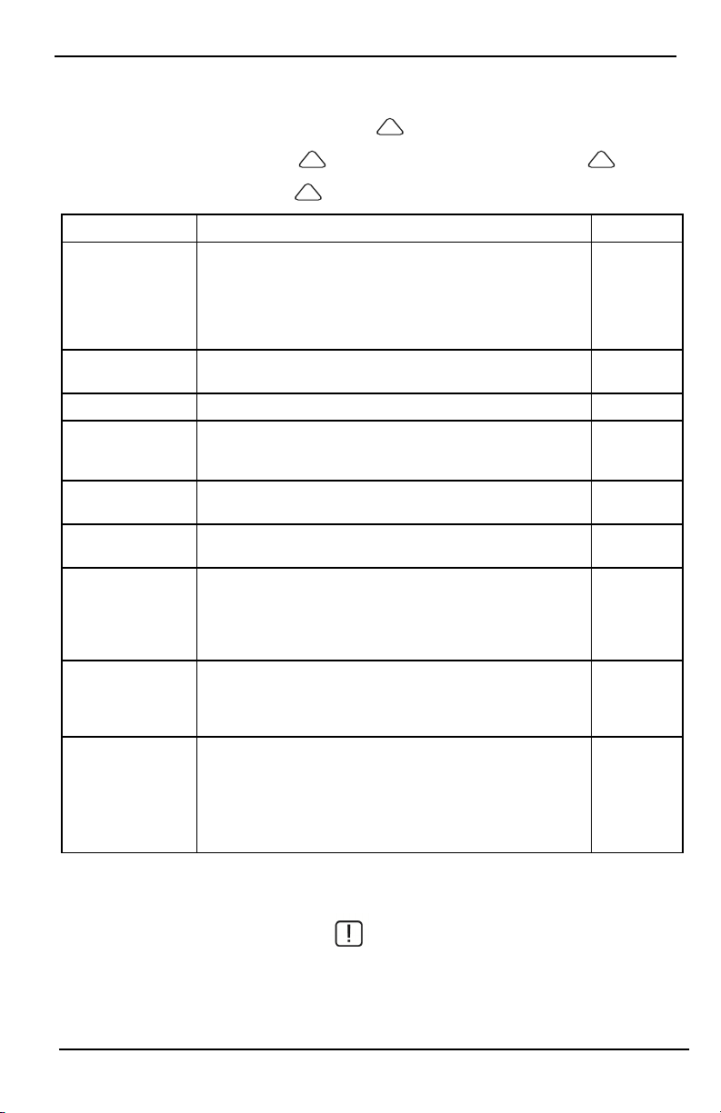
Störungen
Störungen
Wird eine Störung erkannt, leuchtet die Anzeige Störung (!) oder System und das Bedienteil geben alle 10
Sekunden einen Signalton ab. Drücken Sie (!), um die Signalt öne abzuschalten. Drücken Sie (!), um die
Störung anzuzeigen. Die Anzeige Störung (!) oder System blinkt. Die entsprechende Störung leuchtet auf.
Störungen Anmerkungen Aktion
Batterie schwach Allgemeine Systemüberwachung
Service erforderlich
(Drücken für mehr
Details)
Netzausfall
Telefon Störung Das System hat erkannt, dass die Telefonleitung getrennt ist. Service rufen
Kommunikati onsfehler
Linienfehler
Linie Sabotage
Drahtlosgerät Batterie
schwach
Verlust der Uhr
Grenze überschritten
Sirenenschaltkreis HF-Störung erkannt
Allgemeine Systemstörung Zentrale Batterie schwach
Allgemeine Systemsabotage Stromausfall Zentrale
Bei Stromausfall arbeitet die Anlage für mehrere Stunden mit Akkuversorgung weiter.
Das System hat versucht, mit der Notrufzentrale zu kommunizieren,
jedoch ohne Erfolg. Dies kann auf einen Fehler in der Telefonleitung
zurückzuführen sein.
Das System hat Probleme mit einem oder mehreren Sensoren im System. Drücken Sie zum Anzeigen der Linie.
Das System hat einen Sabotageversuch bei einem oder mehreren Geräten innerhalb Systems erkannt. Drücken Sie zum Anzeigen der Linie.
Das System hat eine schwache Batterie bei einem oder mehreren Modulen/Sensoren innerhalb des Systems erkannt. Drücken Sie zur Anzeige
einer schwachen Batterie der Linie, des Bedienteils, der Fernbedienung
und der HF-Unregelmäßigkeit. Drücken Sie erneut, um Linienstörungen zu sehen.
Bei vollständigem Versorgungsausfall (Netz und Akku) müssen Uhrzeit und Datum neu programmiert werden.
[01] Interaktive Zone: Die Anzahl der Zonen, die in der Alarmzentrale
konfiguriert sind, wird von der ADC-Firmware nicht unterstützt (z. B.
> 220).
[02] Interaktive Part.: Die Anzahl der Partitionen, die in der Alarmzentrale konfiguriert sind, wird von der ADC-Firmware nicht unterstützt (z. B. > 8).
Service rufen
Service rufen
Service rufen
Service rufen
Service rufen
Service rufen
Programmieren
Sie Uhrzeit
und Datum
neu
Alarmspeicher
Wenn ein Al arm anliegt, blinkt die Alarmanzeige.
Zur Anzeige, welche(r) Sensor(en) den Alarm ausgelöst hat/haben, ti ppen Sie auf Alarme.
Die Meldernummer des ausgelösten Alarms wird angezeigt (z.B. Linie 3). Mit [<][>] zeigen Sie die Melder im
Alarmspeicher an. Drücken Sie zum Verlassen der Funktion Zurück oder Start. Zum Löschen des Speichers
- 14 -
Page 83
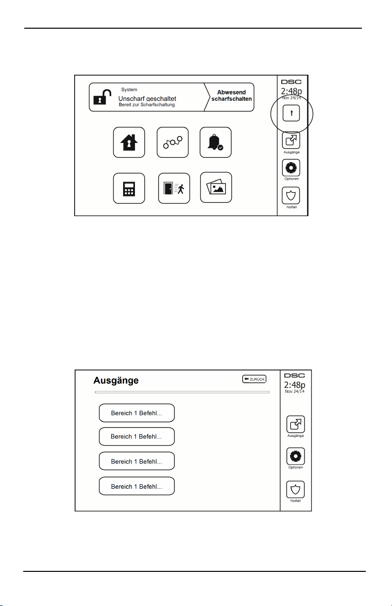
Störungen
schalten Sie das System scharf und unscharf. Wurde im scharfgeschalteten Zust and ein Alarm ausgelöst, so ruft das
Bedienteil automatisch den Alarmspeicher auf, wenn Sie das System unscharf schalten. In diesem Fall seien Sie vorsichtig, da sich ein Einbrecher noch im Gebäude bzw. im gesicherten Bereich befinden könnte.
Abbildung 5- Alarmspeicher
Sensor zurücksetzen
Bestimmte Melder müssen nach Erkennung eines Alarmzustands zurückgesetzt werden, um den Alarmzustand zu
verlassen (z.B. Glasbruchmelder, Rauchmelder usw.). Fragen Sie Ihren Errichter, ob diese Funktion für Ihr System
benötigt wird.
Zum Rücksetzen der Melder, drücken Sie die Schaltfläche Rücksetzen (Befehlsausgang 2, falls der Errichter keine
Kennzeichnung programmiert hat) auf dem Bildschirm Ausgänge. Wenn ein Melder sich nicht zurücksetzen lässt,
kann es sein, dass er noch immer einen Alarmzustand erkennt. Wird der Melder erfolgreich zurückgesetzt, so wird
der Alarm abgebrochen. Ist die Rücksetzung nicht erfolgreich, so wird der Alarm erneut aktiviert bzw. fortgesetzt.
Ausgänge
Ihr Errichter hat diese Schaltflächen möglicherweise für weitere Funktionen programmiert (Rauchmelder nach
Alarm zurücksetzen, Öffnen der Garagentür usw.). Zur Aktivierung dieser Funktionen drücken Sie Ausgang und
drücken Sie dann die entsprechende Option. Für zusätzliche Informationen siehe Abschnitt: Melder zurücksetzen.
Abbildung 6- Ausgänge
- 15 -
Page 84

Zusätzliche Funkti onen
Zusätzliche Funktionen
Fotos
Sie können eine Diashow mit Fotos zur Anzeige auf dem Bedienteil erstellen. Fotos werden mit einer SD-Karte hinzugefügt (32 x 24 x 2,1 mm. Gehört nicht zum Lieferumfang).
Die Fotos müssen im Format .jpg sein und können bis zu 1280 x 720 groß sein. Für beste Ergebnisse verwenden
Sie eine Auflösung von 800 x 480. Verwenden Sie eine Fot obearbeitungs-Software, um die Größe Ihrer Fotos anzupassen.
Um die Diashow zu starten, stellen Sie den Bildschirmschoner auf Fotomodus ein. Die Diashow wird automatisch
wiedergegeben, bis der Zeitablauf erreicht ist oder der Bildschirm erneut angetippt wird.
Zum Hinzufügen von Fotos gehen Sie wie folgt vor:
1. Tippen Sie auf Optionen, Benutzerfunktionen, Bedienteilkonfiguration, Einzelbild, Fotos wählen. Es werden die
Miniaturbilder der Fotos auf Ihrer SD-Karte angezeigt.
2. Tippen Sie auf ein Bild, um es der Diashow hinzuzufügen. Tippen Sie ein zweites Mal darauf, um es zu entfernen.
Verwenden Sie den Schieberegler für die Intervall zeit zur Programmierung des Zeitraums, den jedes Foto angezeigt
wird; von 5 Sekunden bis 1 Minute.
Verwenden Sie den Schieberegler für den Einzelbild-Zeitablauf, um einzustellen, wie lange Ihre Diashow läuft;
von 1 Minuten bis 2 Stunden. Wählen Sie Nie, um die Diashow solange laufen zu lassen, bis der Bildschirm
erneut angetippt wird.
Hinweis: Maximal 255 Fotos werden unterstützt.
Schnell verlassen
Ist das System scharf und Sie möchten den gesicherten Bereich verlassen, so benutzen Sie die Funktion Schneller
Ausgang, um die Unscharfschaltung und erneute Scharfschaltung des Systems zu vermeiden. Zur Aktivierung dieser Funktion tippen Sie auf das Symbol Schneller Ausgang. Sie haben 2 Minuten zum Verlassen des gesicherten
Bereichs durch die Ausgangstür. Nachdem die Tür wieder geschlossen wurde, wird die verbleibende Ausgangszeit
verworfen.
Programmierung von Datum und Uhrzeit
Tippen Sie auf Optionen. Wählen Sie Benutzerfunktionen [Mastercode] und wählen Sie dann Zeit & Datum. Tippen Sie auf den Bereich, den Sie umstellen möchten und ändern Sie Zeit/Datum mit den Pfeilen aufwärts/abwärts.
Anschließend drücken Sie Speichern.
Bedienteil-Modus
Diese Option ermöglicht es dem HS2TCHPRO/HS2TCHPROBLK Touchscreen, wie ein herkömmliches DSCBedienteil zu funktionieren.
Türgong (Gong aktivieren/deaktivieren)
Das Bedienteil zeigt den aktuellen Status der Türgong-Funktion (aktiviert oder deaktiviert). Um die entgegengesetzte Funktion zu wählen, tippen Sie auf das Symbol „Gong“. Drei Signaltöne zeigen an, dass der Türgong aktiviert ist (EIN). Ein langer Signalton zeigt an, dass der Türgong deaktiviert ist (AUS).
Hinweis: Die Türgongfunktion darf nur im unscharf geschalteten Modus verwendet werden.
Linienabschaltung
Das Display ermöglicht Ihnen die Anzeige des Status der Linien des Systems.
- 16 -
Page 85
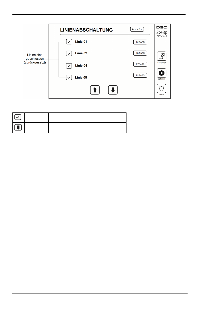
Einstellungsmenü
Abbildung 7- Linie geschlossen
Linienstatusanzeigen
Betriebsbereit Linie ist geschlossen
Offen Die Linie ist offen und muss geschlossen werden
Abgeschaltete Linien
Benutzen Sie di e Linienabschaltfunktion, wenn eine Linie offen ist, aber das System scharfgeschaltet werden soll.
Abgeschaltete Lini en lösen im geöffneten Zustand keinen Alarm aus. Das Abschalten von Linien verringert das
Sicherheitsniveau. Schalten Sie eine Linie ab, weil sie nicht funktioniert, so wenden Sie sich umgehend an den
Kundendienst, um das Problem zu beheben und Ihr System wieder voll betriebsfähig zu machen.
Achten Sie darauf, dass keine Linien versehentlich umgangen werden, wenn Sie Ihre Anlage scharfschalten. Linien
können nur abgeschaltet werden, wenn das System unscharf ist. Abgeschaltete Linien werden automatisch jedes
Mal aufgehoben, wenn das System unscharf geschaltet wird und sie müssen vor dem nächsten Scharfschalten ggf.
erneut abgeschaltet werden.
Hinweis: Die Umgehung von 24-Stunden-Linien kann nur manuell aufgehoben werden.
Hinweis: Aus Sicherheitsgründen hat Ihr Errichter das System so programmiert, dass bestimmte Lini en nicht abge-
schaltet werden können. (z.B. Rauchmelder).
Linienabschaltung mit einem HS2TCHPRO/HS2TCHPROBLK
Wenn Sie auf der Seite Linienstatus sind, scrollen Sie auf/ab durch die gewünschten Linien und tippen Sie auf das
Symbol Abschaltung, um die Linie abzuschalten. Zum Aufheben der Abschaltung einer Linie tippen Sie auf das
Symbol Abschaltung aufheben.
Hinweis: Bei UL-gelistete Installationen können Linien nur manuell abgeschaltet werden.
Einstellungsmenü
Zugriff auf folgende Funktionen mit Tastendruck auf Optionen rechts auf der Startseite. Siehe Online-Benutzerhandbuch HS2TCHPRO/HS2TCHPROBLK Benutzerhandbuch für weitere Informationen.
l Zugangscodes
l Errichtermenü
l Benutzer-Funktionen
l Gong aktiviert/deaktiviert
- 17 -
Page 86
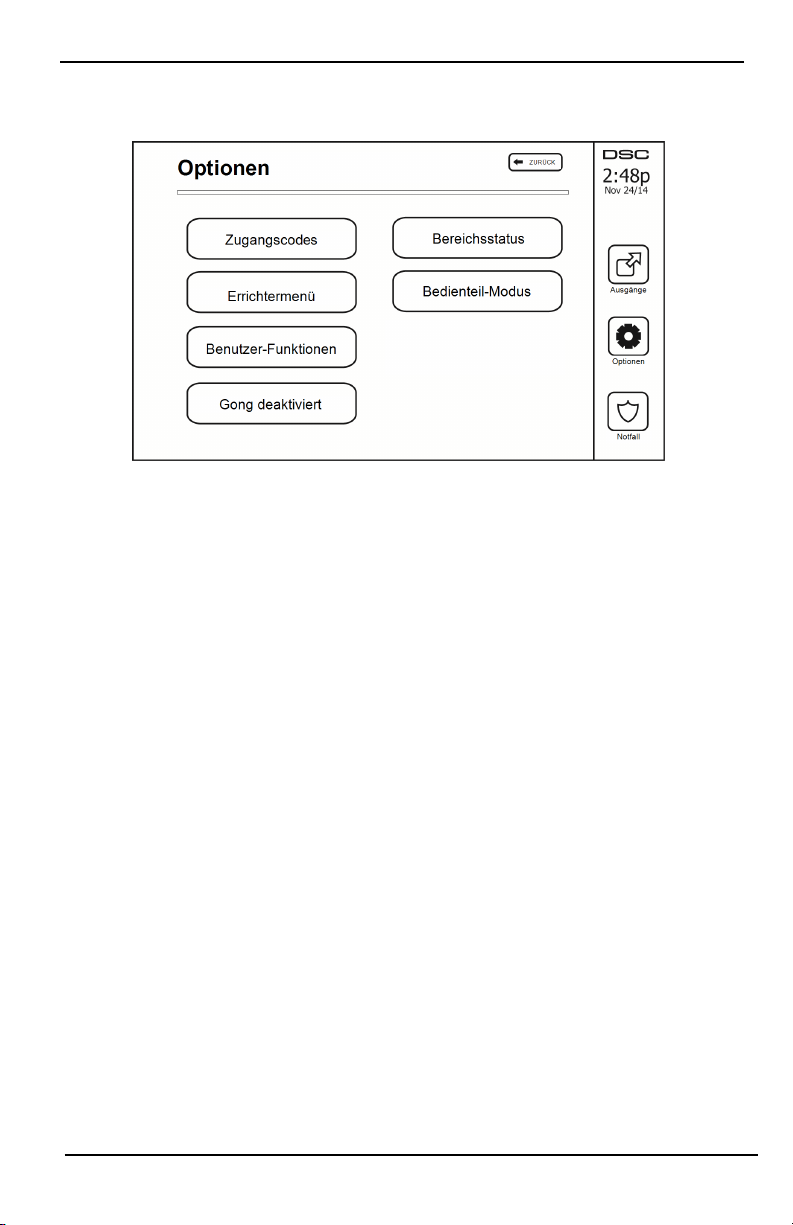
Einstellungsmenü
l Bereichsstatus
l Bedienteil-Modus
Abbildung 8- Optionen
Zugangscodes
Wenn Zugangscodes i m Menü Optionen gewählt werden, fordert Sie das Bedienteil zur Eingabe eines Mastercodes
auf. Wird ein gültiger Mastercode eingegeben, so wird ein Zahlenfeld mit Pfeilen zum Scrollen durch die Liste der
Benutzer angezeigt. Drücken Sie die Auswahlschaltfläche zur Eingabe der Benutzeroptionen.
Zugangscode einstellen: Fügt den 4-stelligen oder 6-stelligen Code hinzu bzw. ermöglicht die Bearbeitung
Bereiche einstellen: Ordnet den Benutzer Bereichen zu
Benutzer Optionen: Aktiviert/deaktiviert verschiedene Optionen für den Benutzer
Benutzer löschen: Löscht den Benutzer im System
Die Zugangscodes haben programmierbare Attribute, die Linienabschaltung oder einmalige Aktivierung zulassen.
Mastercode (Zugangscode 01): Der Mastercode, sofern programmiert, kann nur durch den Errichter geändert
werden.
Überwachungscodes: Diese Codes können zur Programmierung zusätzlicher Codes benutzt werden, die gl eiche
oder unbedeutendere Attribute haben. Nach der Programmierung erhalten die Überwachungscodes die Attribute des
Mastercodes. Diese Attribut e können geändert werden. Jeder Benutzercode kann zu einem Überwachungscode
gemacht werden, indem das Benutzercode-Attribut 1 aktiviert wird (Einzelheiten nachstehend).
Nötigungscodes: Nötigungscodes sind Standard-Benutzercodes, welche den Nötigungs-Berichtscode an die Not-
rufzentrale übertragen, wenn Sie auf dem System zur Ausführung einer Funktion eingegeben werden. Jeder Benutzercode kann zu einem Nötigungscode gemacht werden, indem das Benutzercode-Attribut 2 aktiviert wird
(Einzelheiten nachstehend).
Hinweis: Nötigungscodes sind zum Aufrufen von Benutzerprogrammierung, Master-Funktionen oder des Errichterbereichs ungültig.
Hinweis: Zugangscodes können ni cht als Duplikat oder als ein „Code +/- 1“ programmiert werden.
Transponder zuordnen
Abhängig von der Programmierung Ihres Bedienteils können Transponder entweder zur Scharf-/Unscharfschaltung
des Systems oder zur Ausführung einer programmierten Funktion verwendet werden (z.B. Entriegeln einer Schrankoder Lagertür). Halten Sie den Transponder vor das Lesegerät.
1. Drücken Sie [*][5][Master-/Überwachungscode].
2. Geben Sie einen 4-stelligen oder 6-stelligen Benutzercode ein.
- 18 -
Page 87

Einstellungsmenü
3. Drücken Sie 2.
4. Führen Sie den registrierten Transponder zum Lesegerät.
Transponder löschen
Zum Löschen eines Transponders gehen Sie wie folgt vor:
1. Wähl en Sie Optionen, Zugangscodes [geben Sie den Mastercode ein].
2. Wähl en Sie einen zu löschenden Benutzer.
3. Wähl en Sie Transponderprogrammierung und löschen Sie.
Benutzercode-Attribute
1. Die Standardattribute eines neuen Codes sind die Attribute des Codes, der zur Eingabe der Benutzer-Programmierung benutzt wird; unabhängig davon, ob es sich um einen neuen Code oder einen bestehenden
Code handelt.
2. Der System-Mastercode 01 hat Bereichszugang für alle Bereiche und die Attribute 3-4 standardmäßig
aktiviert.
Hinweis: Diese Attribute können nicht geändert werden.
Ständige Attribute (alle Codes außer Errichter und Wartung)
Scharfschalten/Unscharfschalten: Jeder Zugangscode mit aktiviertem Bereichszugang ist zum Scharfschalten
und Unscharfschalten des Bereichs gültig.
Befehlsausgänge ([*][7][1], [*][7][2], [*][7][3] und [*][7][4]): Wenn diese Ausgänge Zugangs-
codeeingabe erfordern, ist jeder Zugangscode mit Bereichszugang für das Ausführen der Befehlsausgangsfunktionen in diesem Bereich gültig.
Programmierbare Attribute
1. Überwachungscode 5. Für zukünftige Benutzung
2. Nötigungscode 6. Für zukünftige Benutzung
3. Linienabschaltung aktiviert 7. Sirenenanschlag bei Scharfschalten/Unscharfschalten
4. Fernzugriff 8. Gelegentlicher Benutzer-Code
Sirenenanschlags-Attribut
Dieses Attribut dient der Festlegung, ob ein Zugangscode einen Scharfschalten/Unscharfschalten-Sirenenanschlag
bei Eingabe für Abwesend Scharfschalten erzeugen soll. Die Fernbedienungen mit Zugangscodes können Scharfschalten/Unscharfschalten-Sirenenanschl äge erzeugen. Auf Wunsch kann diese Option mit Codes benutzt werden,
die manuell eingegeben werden. Bitte wenden Sie sich zwecks Programmierung an Ihren Errichter.
Hinweis: Der Mastercode kann das Sirenenanschlags-Attribut nicht benutzen, wird jedoch benötigt, um es für
andere Codes zu aktivieren.
Hinweis: Diese Funktion verhindert nicht die Scharfschalten/Unscharfschalten-Sirenenanschläge, wenn ein
Zugangscode, der einer Fernbedienung zugeordnet ist, manuell am Bedienteil eingegeben wird.
Hinweis: Diese Funktion dient der Verkündigung von Brand-Störsignalen und ebenfalls Störungen für medizinische Anwendungen.
Bereichszuordnung
1. Dieser Abschnitt dient der Zuordnung von Benutzern zu verfügbaren Bereichen. Zur Zuordnung von
Bereichen gehen Sie wie folgt vor:
2. Wähl en Sie Optionen > Zugangscodes.
3. Geben Sie den Mastercode ein.
4. Wähl en Sie einen Benut zer.
5. Wähl en Sie Bereichsattribute.
6. Wähl en Sie den/ die Bereich(e), die dem Benutzer zugeordnet werden sollen.
Hinweise zu Zugangscodes und Programmieren
- 19 -
Page 88

Einstellungsmenü
l Die Attribute des Mastercodes können nicht geändert werden.
l Wenn ein neuer Code in der Benutzerprogrammierung programmiert wird, wird er gegen alle anderen
Codes im System geprüft. Wird ein duplizierter Code erkannt, so erfolgt ein Fehlersignal und er wird auf
seinen vorherigen Wert zurückgestellt. Dies betrifft sowohl 4-stelli ge wie auch 6-stellige Codes.
Zugangscode löschen
Zum Löschen eines Codes wählen Sie den Code und dann Benutzer löschen. Das System löscht den Code sofort
und kehrt zum Benutzer zurück, um einen neuen Code zu wählen.
Errichtermenü
Diese Funkti onen sind nur zur Benutzung durch den Errichter.
Benutzer-Funktionen
Schalten Sie zuerst das System unscharf und geben Sie dann Optionen, Benutzerfunktionen und dann Mastercode
ein. Dieser Befehl wird für den Zugang zur folgenden Liste der Masterfunktionen im System benützt:
Zeit und Datum
Geben Sie Zeit und Datum wie gewünscht ein.
Automatische Scharfschaltzeit
Das System kann programmiert werden, um sich täglich zu einer vorprogrammierten Zeit scharf zu schalten. Beim
Aufrufen dieses Bereichs geben Sie die gewünschte automatische Scharfschaltzeit für jeden Wochentag ein.
Zur gewählten automatischen Scharfschaltzeit ertönt der Summer des Bedienteils für einen programmierten Zeitraum (nur durch den Errichter programmierbar), um zu warnen, dass die automatische Scharfschaltung läuft. Di e
Sirene kann während des Warnzeitraums ebenfalls zum Anschlagen alle 10 Sekunden programmiert werden. Wenn
der Warnzeitraum komplett ist, schaltet das System ohne Ausgangsverzögerung und im Abwesendmodus scharf.
Die automatische Scharfschaltung kann durch Eingabe eines gültigen Zugangscodes nur während des programmierten Warnzeitraums abgebrochen oder verschoben werden. Die automatische Scharfschaltung wird zur selben Zeit am nächsten Tag versucht. Wird die automatische Scharfschaltung abgebrochen oder verschoben, so wird
der Löschcode für die automatische Scharfschaltung übertragen (sofern programmiert).
Wird die Scharfschaltung durch einen der folgenden Umstände verhindert, so wird die Löschung der automatischen Scharfschaltung übertragen:
l AC / DC Scharfschaltung verhindert
l Verschlusssystem Sabotagen
l Linienerweiterung Aufsicht Fehler
Hinweis: Für UL/ULC-gelistete Installationen muss die automatische Scharfschaltfunktion abgebrochen werden,
wenn sich Linien in nicht normalem Zustand befinden.
DLS aktivieren/System-Service zulassen
Falls aktiviert, kann der Errichter auf die Errichterprogrammierung per Fernzugriff (DLS) zugreifen. Das DLS-Fenster bleibt für 6 Stunden geöffnet, während dieser Zeit kann der Errichter DLS unbegrenzt aufrufen. Nach dem
Ablauf des 6-Stunden-Fensters bleibt die Errichterprogrammierung wieder bis zum erneuten Öffnen des Fensters
geschlossen.
Ereignisspeicher
l Zeigt Datum, Uhrzeit und eine voll ständige Beschreibung des Ereigni sses an
l Das Protokoll zeigt das jüngste Ereigni s oben und das älteste Ereignis unten in der Liste an
l Der Pfeil links durchläuft die Zeit vorwärts
l Der Pfeil rechts durchläuft die Zeit rückwärts
l Mit Zurück kehren Sie in das Startmenü zurück
l Nach 30 Sekunden ohne Eingabe kehren Sie in das Startmenü zurück
- 20 -
Page 89
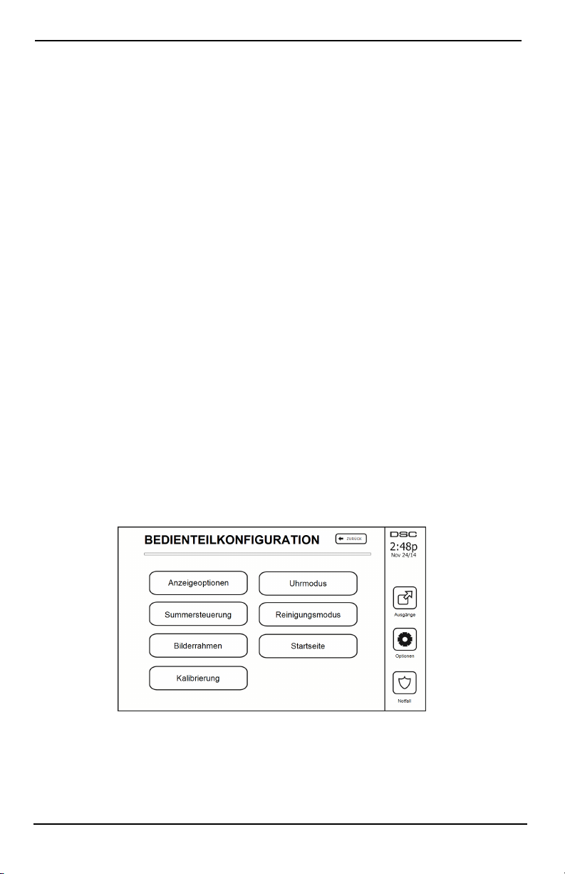
Einstellungsmenü
Systemtest
Der Signalausgang, die Anzeigen des Bedienteils und das Wählgerät des Systems werden getestet. Dieser Test
misst auch die Stand-by-Batterie der Alarmzentrale.
Wichtig:
l Zur Gewährleistung, dass Ihr Syst em auch weiterhin bestimmungsgemäß funkt ioniert, müssen Sie es
wöchentlich testen.
l Für PRIVATE GESUNDHEITSFÜRSORGE UL-gelistete Anwendungen muss das System ebenfalls
wöchentlich ohne Netzspannung getestet werden. Zum Abtrennen der Netzversorgung von der Zentrale
entfernen Sie di e Schraube aus der Haltenase des Steckernetzteils und ziehen Sie das Netzteil von der
Steckdose ab. Nach dem Testen des Geräts nur mit Batterieversorgung schließen Sie das Netzteil wieder
an der Steckdose an und schrauben Sie die Haltenase wieder an, sodass das Netzteil sicher mit der Steckdose verbunden ist.
l Sollte Ihr System nicht ordnungsgemäß funktionieren, kontaktieren Sie unmittelbar Ihren Errichter.
l Alle Rauchmelder müssen vom Errichter, der sie i nstalliert hat, einmal pro Jahr geprüft werden, um
sicherzustellen, dass diese ordnungsgemäß funktionieren.
Automatische Kontrolle Scharfschaltung/Unscharfschaltung
Durch Drücken von Auto-Scharf im Menü Benutzerfunktion wird die Auto-Scharf- und Auto-Unscharf-Funktion je
Bereich aktiviert (drei Signaltöne) oder deaktiviert. Mit der Aktivierung dieser Funktion schaltet die Al armzentrale
automatisch jeden Tag um dieselbe Zeit im Abwesendmodus scharf (Anwesend-/Abwesendlinien aktiv) oder
unscharf. Die Zeit der automatischen Scharfschaltung wird mit der Schaltfläche Auto-Scharf Zeit programmiert. Die
automatische Unscharfschaltung muss vom Systemerrichter programmiert werden.
Benutzer Aufruf
Diese Option gibt Ihrem Dienstanbieter zur Fernwartung vorübergehenden Zugriff auf die Alarmzentrale.
Errichter-Rücksetzung
Wenn auf Ihrem System ein Alarm ausgelöst wurde, lässt das System keine erneute Scharfschaltung zu (Betriebsbereit-LED ist erloschen). Sie müssen sich an Ihren Errichter wenden. Er überprüft und setzt das System für Sie
zurück. Hierzu kann ein Besuch zur Überprüfung Ihres Systems notwendig sein. Nach der Rücksetzung funktioniert Ihr System wieder einwandfrei.
Bedienteilkonfiguration
Abbildung 9- Bedienteilkonfiguration
Anzeigeoptionen: Stellt die Helligkeit und Abschaltung des Touchscreens sowie die Optionen des Bild-
schirmschoners ein.
Summersteuerung: Regelt die Summerlautstärke des Touchscreens. Hinweis: Für SIA CP-01 darf die Sum-
merlautstärke nicht auf den Mindestwert eingestellt werden.
Hinweis: Für UL/ULC-Installationen darf die Summerlautstärke nur auf den Standardpegel eingestellt werden.
- 21 -
Page 90

Einstellungsmenü
Bilderrahmen: Wählt die Bilder, die in der Diashow gezeigt werden.
Kalibrierung: Kalibriert den Touchscreen.
Uhrmodus: Zeigt die digitale Uhr an.
Reinigungsmodus: Ermöglicht dem Benutzer di e Berührung des Di splays (z. B. zum Reinigen), ohne dabei Funk-
tionen zu aktivieren oder zu deaktivieren. Der Bildschirm bleibt für 30 Sekunden in diesem Modus und kehrt dann
in das Menü Bedienteilkonfiguration zurück.
Abbildung 10- Reinigungsmodus
Startseite: Kann in zwei Ansichten konfiguriert werden, entweder als klassisch (quadratisch) oder zeitgemäß
(abgerundet).
Gong aktiviert/deaktiviert
Türgong: Um die Türgong-Funktion ein- oder auszuschalten, tippen Sie auf das Symbol Gong. 3 Signaltöne zei-
gen an, dass der Gong eingeschaltet i st. 1 langer Signalton zeigt an, dass der Gong ausgeschaltet ist.
Scharfschalten
Anwesend Scharfschalten: schaltet das System im Anwesendmodus scharf
Abwesend Scharfschalten: schaltet das System im Abwesendmodus scharf
Nacht Scharfschalten: Zur vollständigen Scharfschaltung des Systems aus dem Anwesendmodus drücken Sie
Nacht Scharfschalten. Alle Innenraum-Linien werden nun scharfgeschaltet, außer Geräte, die als Nachtlinien programmiert wurden. Nachtlinien werden nur im Abwesendmodus scharfgeschaltet. Dies erlaubt beschränkte Bewegungsfreiheit im Gebäude, wenn das System vollständig scharfgeschaltet ist. Achten Sie darauf, dass der Errichter
Ihnen eine Liste der als Nachtlinien programmierten Linien überlässt. Wenn die Innenraum-Linien aktiviert wurden (d. h. Nacht Scharfschalten), müssen Sie zum Unscharfschalten Ihren Zugangscode eingeben, um Zugang zu
Innenbereichen zu erhalten, di e nicht als Nachtlinien programmiert wurden.
Schnell verlassen: si ehe Abschnit t: Schnell verlassen
Global Abwesend Scharfschalten: schaltet all e Bereiche, denen der Benutzercode zugeordnet ist, im Abwe-
sendmodus scharf.
Global Anwesend Scharfschalten: schaltet all e Bereiche, denen der Benutzercode zugeordnet ist, im Anwe-
sendmodus scharf.
Kein Zugang Scharfschalten: schaltet das System ohne Zugang scharf.
Bereichsstatus
Zum Ansehen des Bereichsstatus, drücken Sie Optionen, Benutzerfunktionen und dann Bereichsstatus. Das Bedienteil zeigt den Basisstatus für bis zu 8 Bereiche, abhängig von der Konfiguration Ihres Systems. Jeder Bereich wird
- 22 -
Page 91

Verwalten von Bereichen
zugleich mit seinem aktuellen Status ident ifiziert.
Abbildung 11- Bereichsstatus
Bedienteil-Modus
Diese Option ermöglicht es dem HS2TCHPRO/HS2TCHPROBLK Touchscreen, wie ein herkömmliches DSCBedienteil zu funktionieren.
Verwalten von Bereichen
Ein Bereich ist ein begrenzter Abschnitt der Räumlichkeiten/des Grundstücks, der unabhängig von den anderen
Bereichen überwacht wird. Bereiche einer Alarmanlage können von Vorteil sein, wenn das Grundstück Nebengebäude umfasst, die unabhängig von einem Hauptbereich gesichert werden müssen oder wenn das Haus über eine
separate Wohnung verfügt. Jeder Bereich kann sein eigenes Bedienteil haben oder ein Bedienteil kann auf alle
Bereiche zugreifen. Der Benutzerzugriff auf Bereiche wird durch Zugangscodes gesteuert. Ein Mastercode kann auf
die gesamte Alarmanlage und die Bereiche zugreifen, ein Benutzercode ist eingeschränkt und kann nur Bereichen
zugewiesen werden.
Bereiche
Bedienteile können so konfiguriert werden, dass sie einen Bereich oder alle Bereiche steuern können.
Hinweis: Der Zugriff auf diese Funktion muss von Ihrem Errichter konfiguriert werden.
Einzelbereichsbetrieb
Bedienteile für einzelne Bereiche ermöglichen den Zugriff auf Alarmfunktionalitäten für einen zugewiesenen
Bereich.
Bedienteile für einzelne Bereiche verhalten sich wie folgt:
l Anzeige des Status Scharfgeschaltet des Bereichs.
l Zeigt offene Linien an, wenn diese dem Bereich des Bedienteils zugewiesen wurden.
l Zeigt abgeschaltete Linien an und ermöglicht das Abschalten von Linien oder das Erstellen von abzu-
schaltenden Linien-Gruppen, die dem Bereich des Bedienteils zugewiesen sind.
l Zeigt Störungen der Alarmanlage an (schwache Batterie des Systems, Störungen der Sys-
temkomponenten/Sabotage).
l Zeigt Alarme im Speicher an, die in dem Bereich aufgetreten sind.
l Sie ermöglichen es, den Türgong zu akt ivieren/deaktivieren.
l Alarmanlagentest (Sirene ertönen/Programme, die den Bereichen zugewiesen wurden).
l Kennzeichnen der Programmierung (Linie, Bereich und Benutzerkennzeichnungen für den Bereich).
l Befehlsausgabensteuerung (zugeordnete Ausgänge zu den Bereichen oder globale Ausgänge wie Rauch-
melder-Zurücksetzung).
l Temperaturen.
- 23 -
Page 92

Verwalten von Bereichen
Ausleihen von Bedienteilen für andere Bereiche
Das HS2TCHPRO/HS2TCHPROBLK Touchscreen-Bedienteil kann ausgeliehen werden, um andere Bereiche zu
bedienen. Wird ein Bedienteil an einen anderen Bereich verliehen, so verhält es sich auf diesem Bereich so, als
wäre es ihm ursprünglich zugordnet. Ein Zugangscode muss eingegeben werden, bevor ein Bedienteil an einen
anderen Bereich ausgeliehen wird. Ein Zugangscode ist ebenfalls erforderlich, um die Funktionen in diesem
Bereich auszuführen.
Zum Ausleihen eines Bedienteils für einen anderen Bereich gehen Sie wie folgt vor:
1. Wähl en Sie Optionen > Bereich Status.
2. Geben Sie Ihren Zugangscode ein.
3. Wähl en Sie den Bereich, dem das Bedienteil geliehen werden soll. Ist das Bedienteil für mehr als 30
Sekunden inaktiv, kehrt es in seinen Originalbereich zurück.
Globaler Bedienteilbetrieb
Sobald ein gültiger Zugangscode eingegeben wurde, zeigt ein globales Bedienteil den Status aller Bereiche an, für
die der Benutzer eine Berechtigung zur Anzeige hat. In dieser Übersicht können Sie das globale Bedienteil einem
Bereich leihen, alle Bereiche scharf- oder unscharf schalten. Der Status jedes Bereichs wird durch ein Bereichsstatussymbol gekennzeichnet. Eine Erklärung der Bereichsstatussymbole finden Sie in der nachstehenden Tabelle.
Die Schaltflächen Gl obal scharfschalten und Global unscharf schalten schaltet alle angezeigten Bereiche scharf
bzw. unscharf.
Zum Verleihen eines globalen Bedienteils an einen anderen Bereich gehen Sie wie folgt vor:
1. Wähl en Sie Bereich Status.
2. Wähl en Sie den Bereich, dem das Bedienteil geliehen werden soll.
Abbildung 12- Globaler Bedienteilmodus
Bereich
Statussymbol
Beschreibung
GRÜNER HINTERGUND
Bereich ist bereit, scharfgeschaltet zu werden
Bereich ist in Ausgangsverzögerung
GRAUER HINTERGRUND
Bereich ist nicht bereit, scharfgeschaltet zu werden
Bereich ist im Alarmzustand
- 24 -
Page 93

Verwalten von Bereichen
Bereich
Statussymbol
Beschreibung
Bereich ist in Zugangsverzögerung
Bereich ist scharfgeschaltet
Feuer- und CO-Linientypen
l Löst eine Brandmeldelinie einen Alarm aus, so begibt sich nur der Bereich, welchem di e Brandmeldelinie
zugeordnet ist, in Alarmzustand. Andere Bereiche behalten ihren aktuellen Zustand bei.
l Wird die [F] Taste auf einem globalen Bedienfeld zum Auslösen eines Alarms benutzt, so begeben sich
alle aktivierten Bereiche in Alarmzustand.
l Ein oder mehrere Feuer-Bedienteil(e) kann/können sich in einem jeden beliebigen Bereich befinden.
l Bei Alarm erscheint die automatische Scrollanzeige des Feueralarms auf allen Bereichs-Bedienteilen und
globalen Bedienteilen. Die Zurücksetzung von Feueralarm und Brandmeldeanlage kann direkt von jedem
Bedienteil aus erfolgen. Um einen Feueralarm oder Kohlenmonoxidalarm von einem globalen Bedienteil
stummzuschalten, ist es erforderlich, dass das globale Bedienteil an einen der Bereiche ausgeliehen wird.
- 25 -
Page 94

Testen des Systems
Testen des Systems
Hinweis: Bevor Sie einen Systemtest durchführen, rufen Sie Ihre Notrufzentrale an und informieren Sie sie über
den Beginn und das Ende des Tests.
Signalgeber des Bedienteils und Sirene testen
Der Systemtest führt zusätzli ch zur Überprüfung der Bedienteil-Statusanzeigen und der Notst romversorgung eine
2-Sekunden-Überprüfung des Signalgebers des Bedienteils und der Sirene durch.
1. Drücken Sie Optionen, Benutzerfunktionen [Mastercode], dann Systemtest. Folgendes passiert:
- Die Anlage aktiviert zwei Sekunden lang alle Bedienteil- Signalgeber und Sirenen. Alle Anzeigen des
Bedienteils leuchten nacheinander auf.
- Die Betriebsbereit-, Scharf-, und Störungs-LEDs blinken für die Dauer des Tests.
2. Zum Verlassen des Menüs drücken Sie [#].
Testen des kompletten Systems
Alle Rauchmelder in dieser Installati on müssen durch den Errichter oder Fachhändler Ihrer Rauchmelder einmal
jährlich getestet werden, um die korrekte Funktion zu gewährleisten. Es liegt in der Verantwortlichkeit des Benutzers, das System wöchentlich zu testen (außer Rauchmelder). Führen Sie einen Systemtest gemäß den Schritten
unter „Signalgeber des Bedienteils und Sirene testen“ durch.
Hinweis: Sollte das System nicht korrekt funktionieren, so wenden Sie sich umgehend an den Kundendienst.
1. Vergewissern Sie sich vor dem Test, dass das System unscharf ist und dass die Betriebsbereit-LED leuchtet.
2. Schließen Sie alle Linien, um das System in den Betriebsbereit-Zustand zurückkehren zu lassen.
3. Führen Sie einen Systemtest gemäß den Schrit ten unter „Signalgeber des Bedienteils und Sirene testen“
durch.
4. Testen Sie die Linien durch aufeinander folgende Aktivierung jedes einzelnen Melders (z.B. Öffnen jeder
Tür/jedes Fensters oder gehen Sie in den Abdeckungsbereich der Bewegungsmelder).
Auf einem Bedienteil HS2TCHPRO/HS2TCHPROBLK wird die folgende Meldung angezeigt, wenn die ein-
zelnen Linien (Melder) aktiviert werden: „Bereit für erzwungene Scharfschaltung“, „Nicht bereit“. Mit der Schaltfläche Linie Status zeigen Sie die offenen Linien an. Die Meldung wird ausgeblendet, wenn die Linien
geschlossen werden.
Hinweis: Einige der oben beschriebenen Funktionen stehen erst zur Verfügung, wenn sie durch den Errichter aktiviert werden. Fragen Sie Ihren Errichter, welche Funktionen auf Ihrem System aktiviert sind.
Gehtestmodus
Der Errichter kann einen Gehtestmodus für das System initiieren. Während des Gehtestmodus blinken die Betriebsbereit-, Scharf-, und Störungs-LEDs, um anzuzeigen, dass der Gehtest aktiv ist. Wenn das System den Gehtestmodus automatisch beendet, gibt es eine akustische Warnung ab (5 Signaltöne alle 10 Sekunden) beginnend 5
Minuten vor der Beendigung des Tests.
Computerzugriff zu Ihrem System gestatten
Von Zeit zu Zeit muss Ihr Errichter möglicherweise Informationen an Ihr Sicherheitssystem übertragen oder dort
abfragen. Ihr Errichter tut dies, indem er einen Computer Ihr System über die Telefonverbindung anrufen lässt. Ihr
System muss zum Empfang dieser „Download“ Anrufe vorbereitet werden. Drücken Sie hierzu Optionen, Benutzerfunktionen [Mastercode], dann System Server/DLS auf dem Touchscreen. Dies ermöglicht den Download für
einen begrenzten Zeitraum. Während dieser Zeit beantwortet das System eingehende Download-Anrufe. Für weitere
Informationen zu dieser Funktion sprechen Sie bitte mit Ihrem Errichter.
- 26 -
Page 95

Referenzblätter
Referenzblätter
Füllen Sie die folgenden Informationen für zukünftiges Nachschlagen aus und bewahren Sie sie auf.
Systeminformationen Aktiviert?
[F] FEUER
[+] Medi-
zinischer Notfall
Die Dauer der Ausgangsverzögerung beträgt
_______ Sekunden
Die Dauer der Zugangsverzögerung beträgt
_______ Sekunden
Für Service
Notrufzentrale Informationen:
Konto: ___________________ Telefon: ________________
Errichter Informationen:
Firma: ___________________ Telefon: ________________
Batterie-Installation / Wartung:
__________________________
__________________________
__________________________
Wenn Sie vermuten, dass ein Fehlalarmsignal an die Notrufzentrale übertragen wurde, so rufen Sie dort
an, um einen unnötigen Einsatz zu vermeiden.
[P] PANIK
- 27 -
Page 96

Zugangscodes (ggf. kopieren)
HS3032/HS3128/HS3248 MASTERCODE [01]: _______________________
Benutzer Zugangscode Benutzer Zugangscode Benutzer
01 35 69
02 36 70
03 37 71
04 38 72
05 39 73
06 40 74
07 41 75
08 42 76
09 43 77
10 44 78
11 45 79
12 46 80
13 47 81
14 48 82
15 49 83
16 50 84
17 51 85
18 52 86
19 53 87
20 54 88
21 55 89
22 56 90
23 57 91
24 58 92
25 59 93
26 60 94
27 61 95
28 62 96
29 63 97
30 64 98
31 65 99
32 66 100
33 67
34 68
Referenzblätter
- 28 -
Page 97

Referenzblätter
Sensor- / Linieninformationen (ggf. kopieren)
Linien Gesicherter Bereich Sensortyp
1
2
3
4
5
6
7
8
9
10
11
12
13
14
15
16
17
18
19
20
21
22
23
24
25
26
27
28
29
30
- 29 -
Page 98

Richtlinien zur Platzierung von Rauch- und CO-Meldern
Richtlinien zur Platzierung von Rauch- und CO-Meldern
Die folgenden Informationen dienen nur einem allgemeinen Überblick und es wird empfohlen, die lokalen Brandschutzbestimmungen bei der Platzierung und Installation von Rauch- und CO-Meldern zu beachten.
Rauchmelder
Untersuchungen haben gezeigt, dass alle Schadensfeuer in Haushalten mehr oder weniger Rauch entwickeln. Experimente mit typischen Feuern in Haushalten weisen darauf hin, dass die erkennbaren Mengen an Rauch in den meisten Fällen erkennbarer Wärmeentwicklung vorausgeht. Aus diesem Grund sollten Rauchmelder außerhalb jedes
Schlafbereichs in jedem Geschoss eines Hauses installiert werden. Die folgenden Informationen dienen nur einem
allgemeinen Überblick und es wird empfohlen, die lokalen Brandschutzbestimmungen bei der Platzierung und
Installation von Rauch-Meldern zu beachten. Es wird empfohlen, zusätzliche Rauchmelder, die über den erforderlichen Minimalschutz hinausgehen, zu installieren. Zusätzliche Bereiche, die zu schützen sind, umfassen: Keller,
Schlafzimmer, speziell jene von Rauchern, Esszimmer, Heizungs- und Wirtschaftsräume und j eden Flur, der nicht
mit den nötigen Geräten geschützt ist. Auf glatten Decken sollten di e Melder als Faustregel in einem Abstand von
9,1 m (30 Fuß) voneinander montiert werden. Andere Abstände können in Abhängigkeit von der Deckenhöhe, der
Luftbewegung, dem Vorhandensein von Dachträgern, ungedämmten Decken usw. nötig sein. Beachten Sie die
Nationalen Feueralarmvorschriften NFPA 72, CAN/ULC-S553-02 oder entsprechende andere nationale Normen für
Montageempfehlungen.
l Platzieren Sie Rauchmelder nicht auf Spitz- und Giebeldächern, da durch den abgeschlossenen Luft-
bereich das Gerät eventuell nicht imstande ist, Rauch zu erkennen.
l Vermeiden Sie Bereiche mit l ebhafter Luftbewegung in der Nähe von Türen, Ventilatoren oder Fenstern.
Rasche Luftbewegung um den Melder verhindert eventuell, dass Rauch in das Gerät gelangt.
l Platzieren Sie Melder nicht in Bereichen mit hoher Luftfeuchtigkeit.
l Platzieren Sie Melder nicht in Bereichen, in denen die Temperatur über 38 °C (100 °F) st eigt oder unter
5 °C (41 °F) fällt.
Rauchmelder müssen in den USA stets entsprechend den Bestimmungen in Kapitel 29 des NFPA 72, der Nationalen Feueralarmvorschriften: 29.5.1.1 eingebaut werden.
Wenn von anderen geltenden Gesetzen, Vorschriften oder Normen für eine bestimmte Art der Belegung gefordert,
müssen genehmigte/zertifizierte Einzel- und Mehrfach-Stations-Rauchmelder wie folgt installiert werden:
1. In allen Schl afräumen und Gästezimmern.
2. Außerhalb eines jeden einzelnen Schlafbereichs der Wohneinheit, innerhalb von 6,4 m (21 Fuß) einer
jeden Tür zu einem Schlafzimmer, wobei der Abstand entlang des Laufweges gemessen wird.
3. Auf jeder Etage einer Wohneinheit, einschließl ich Keller.
4. Auf jeder Ebene einer Wohnunterkunft und eines Pflegebereichs (kleine Einrichtung), einschließlich Keller, außer Kriechkeller und nicht ausgebaute Dachböden.
5. Im Wohnbereich einer Gäste-Suite.
6. In den Wohnbereichen einer Wohnunterkunft und eines Pflegebereichs (kleine Einrichtung).
- 30 -
Page 99
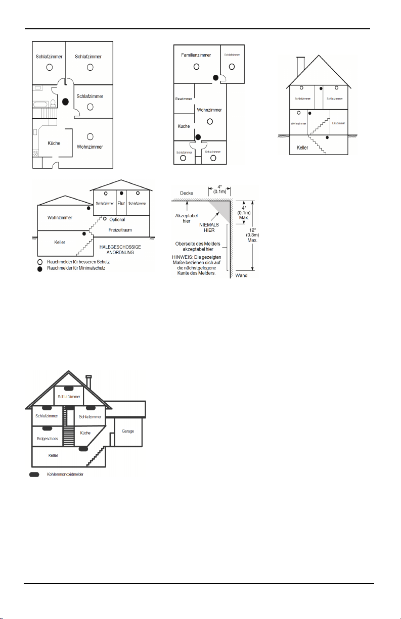
Richtlinien zur Platzierung von Rauch- und CO-Meldern
Kohlenmonoxidmelder
Kohlenmonoxid ist farb-, geruch- und geschmacklos und sehr giftig. Es bewegt sich frei in der Luft. CO-Melder
können die Konzentration messen und geben einen lauten Alarm aus, bevor eine schädliche Menge erreicht wird.
Der menschliche Körper ist im Schlaf am anfälligsten für die Wirkung von CO-Gas. Deshalb sollten CO-Melder in
oder so nahe wi e möglich bei den Schlafbereichen des Hauses platziert werden. Für maximalen Schutz soll te sich
ein CO-Melder auch außerhalb primärer Schlafbereiche oder auf jeder Ebene Ihres Hauses befinden. Abbildung 5
zeigt die empfohlenen Positionen im Haus.
Platzieren Sie den CO-Melder NICHT in folgenden Bereichen:
l Wo die Temperatur unter -10 °C fallen oder über 40 °C steigen kann
l Nahe Bereichen, wo Dämpfe von Farbverdünnern auftreten
l Innerhalb von 1,5 m (5 Fuß) von Geräten mit offenen Flammen wie Heizungen, Öfen und Kaminen
l Innerhalb von Abluftst römungen von Gasmotoren, Lüftungsschächten, Schornsteinen oder Kaminen.
- 31 -
Page 100

Richtlinien zur Platzierung von Rauch- und CO-Meldern
l Platzieren Sie den Melder nicht in unmittelbarer Nähe zu einem Fahrzeugauspuff - dies führt zur Beschä-
digung des Melders.
BITTE BEACHTEN SIE DIE MONTAGE- UND BETRIEBSANLEITUNGEN DES CO-MELDERS UND DIE
SICHERHEITS- UND NOTFALLHINWEISE.
Brandschutzprüfung Zuhause
Lesen Sie diesen Abschnitt für wichti ge Informationen zur Brandsicherheit. Die meisten Brände entstehen Zuhause.
Um diese Gefahr zu minimieren, empfiehlt es sich, dass eine Brandschutzprüfung im Haus durchgeführt und ein
Fluchtplan für die Famili e entwickelt wird.
1. Sind alle elektrischen Geräte und Steckdosen in einem sicheren Zustand? Überprüfen Sie auf durchgescheuerte Kabel, überlastete Stromkreise usw. Wenn Sie unsicher über den Zustand Ihrer Elektro- oder
Haushaltsgeräte sind, lassen Sie diese von einem Fachmann überprüfen.
2. Sind alle brennbaren Flüssigkeiten sicher in verschlossenen Behältern an einem gut durchlüfteten, kühlen Ort aufbewahrt? Vermeiden Sie die Reinigung des Geräts mit brennbaren Flüssigkeiten.
3. Befinden sich gefährliche Materialien (z. B. Streichhölzer) außerhalb der Reichweite von Kindern?
4. Wurden Heizungen und Holzöfen oder ähnliches ordnungsgemäß installiert und sind diese sauber und
in einwandfreiem Zustand? Lassen Sie diese Geräte von einem Fachmann überprüfen.
Feuer-Fluchtplanung
Es ist oft sehr wenig Zeit zwischen der Erkennung eines Brandes und der Zeit, wenn er t ödlich wird, vorhanden.
Deshalb ist es sehr wichtig, dass ein Fluchtplan für die Familie entwickelt und geübt wird.
1. Jedes Familienmitglied sollte sich bei der Entwicklung des Fluchtplans beteiligen.
2. Ermitteln Sie die möglichen Fluchtwege von jedem Ort innerhalb des Hauses aus. Da viele Brände in der
Nacht auftreten, sollte besonderes Augenmerk auf die Fluchtwege aus Schlafräumen gelegt werden.
3. Die Flucht aus einem Schlafzimmer muss möglich sein ohne dass die Innentür geöffnet werden muss.
Ziehen Sie Folgendes in Betracht, wenn Sie die Fluchtpläne erstellen:
l Stellen Sie sicher, dass alle Türen und Fenster an den Außenwänden leicht geöffnet werden können. Stel-
len Sie sicher, dass Fluchtwege nicht mittels Farbe verklebt und dadurch versperrt wurden und dass
Schließmechanismen ordnungsgemäß funktionieren.
l Wenn das Öffnen oder die Verwendung eines Ausgangs für Kinder, ältere Menschen oder Behinderte zu
schwierig ist, sollten Pläne für deren Rettung entwickelt werden. Dies sollte beinhalten, dass diejenigen,
die die Rettung durchführen werden, den Feueralarm sofort hören können.
l Wenn sich der Ausgang über dem Erdgeschoss befindet, sollte eine zugelassene Feuerleiter oder ein Klet-
terseil zur Verfügung gestellt werden, sowie Training in deren Nutzung.
l Ausgänge auf Erdgeschossebene müssen frei gehalten werden. Achten Sie darauf, im Winter Schnee vor
Terrassentüren zu räumen und dass Gartenmöbel oder -geräte Ausgänge nicht blockieren.
l Jede Person muss den festgelegten Ort für die Zusammenkunft kennen, wo dann die Anwesenheit
geprüft werden kann, z. B. auf der anderen Straßenseite oder beim Haus eines Nachbarn. Sobald jeder aus
dem Haus ist, rufen Sie die Feuerwehr.
l Ein guter Plan begünstigt eine schnelle Flucht. Versuchen Sie nicht, das Haus zu durchsuchen und ver-
suchen Sie nicht, das Feuer zu löschen und versuchen Sie auch nicht, Gegenstände einzusammeln, da
dies wertvolle Zeit in Anspruch nimmt. Wenn Sie im Freien sind, betreten Sie das Haus nicht mehr. Warten Sie auf das Eintreffen der Feuerwehr.
l Schreiben Sie den Feuerfluchtplan auf und üben Sie ihn regelmäßig, damit i m Notfall jeder weiß, was zu
tun ist. Überarbeiten Sie den Plan, wenn sich die Bedingungen ändern, wie etwa die Anzahl der Personen
im Haus oder wenn sich an der Konstruktion des Hauses etwas ändert.
l Stellen Sie sicher, dass die Brandmeldeanlage funktionstüchtig ist, indem wöchentliche Tests durch-
geführt werden. Wenn Sie sich unsicher über die Funktionstüchtigkeit sind, wenden Sie sich an den
Errichter.
l Wir empfehlen, dass Sie Ihre örtliche Feuerwehr kontaktieren und sich weitere Informationen
- 32 -
 Loading...