

Page 1
HS2TCHP E Touchscreen User Manual
Ecran tactile HS2TCHP E Manuel de l'utilisateur
HS2TCHP E Gebruikershandleiding Aanraakscherm
HS2TCHP E Touchscreen Benutzerhandbuch
WARNING: This manual contains information on limitations regarding product use, function and information
on the limitation as to liabili ty of the manufacturer. The entire manual should be carefully read.
MISE EN GARDE: Ce manuel contient des informations sur les limitations concernant l’utilisation et le fonctionnement du produit ainsi que des informations sur l es limitations et les obli gations du fabricant Lisez attentivement le guide complet.
WAARSCHUWING: Deze handleiding bevat informatie over beperkingen betreffende het productgebruik, de functie en informatie over de beperking van de aansprakelijkheid van de fabrikant. De hele handleidi ng moet zorgvuldig worden gelezen.
WARNUNG: Dieses Handbuch enthält Informationen hinsichtlich der Einschränkungen bei der Verwendung des
Produkts und der Funktionen und Informationen zu den Einschränkungen bezüglich der Haftung des Herstellers.
Lesen Sie das gesamte Handbuch aufmerksam durch.
Page 2

Table of Contents
Table of Contents 2
Safety Notes 5
Important Safety Instructions 5
Regular Maintenance and Troubleshooting 5
Handling Precautions 5
Cleaning 5
Troubleshooting 5
Introduction 6
General System Operation 6
About Your Security System 6
Carbon Monoxide Detection (must be enabled by your Installer) 7
Fire Detection (must be enabled by your Installer) 7
Testing 7
Monitoring 7
Maintenance 7
Important Notice 7
Specifications and Features 8
Welcome Screen 8
Emergency Keys 9
Arming and Disarming the System 10
Stay Arm (Arming the Perimeter) 10
Silent Exit Delay 10
Disarm 11
Away Arm 11
Exit Delay Time Restart 11
Alarm Cancel Window 11
Bell/Siren Sounds After Away Arming 12
Audible Exit Fault 12
Arming Error 12
Remote Arming and Disarming 12
Using Your System 12
When Alarm Sounds 12
Intrusion (Burglary) Alarm Continuous Siren 12
If the Intrusion Alarm was Accidental 13
Fire Alarm Pulsed Siren 13
Wireless Carbon Monoxide Alarm 13
Troubles 14
Alarm Memory 14
Sensor Reset 15
Outputs 15
Page 3

Additional Functions 16
Photos 16
Quick Exit 16
Time & Date Programming 16
Keypad Mode 16
Door Chime (Chime enable/disable) 16
Zone Bypass 16
Zone Status Indicators 17
Bypassed Zones 17
Bypassing Zones with a HS2TCHP 17
Options Menu 17
Access Codes 18
Assign Proximity Tags 18
Delete Proximity Tags 18
User Code Attributes 19
Inherent Attributes (all codes except installer and maintenance) 19
Programmable Attributes 19
Bell Squawk Attribute 19
Partition Assignment 19
Erasing an Access Code 19
Installer Menu 19
User Functions 20
Time and Date 20
Auto-Arm Time 20
Enable DLS/Allow System Service 20
Event Buffer 20
System Test 20
Auto-Arm/Disarm Control 21
User Call-up 21
Engineer's Reset 21
Keypad Configuration 21
Chime Enabled/Disabled 22
Arming 22
Partition Status 22
Keypad Mode 23
Managing Partitions 23
Partitions 23
Single Partition Operation 23
Loaning a Keypad to Another Partition 23
Global Keypad Operation 24
Fire and CO Zone Types 25
Page 4

SMS Command and Control 26
Looking up the Number to Call for SMS Commands 26
Authorizing User Phones to Send SMS Commands 26
Sending SMS Commands to your System 26
SMS Commands 27
Testing Your System 28
Testing Your Keypad Sounder and Siren 28
Testing Your Entire System 28
Walk Test Mode 28
Allowing Computer Access To Your System 28
Reference Sheets 29
System InformationEnabled? 29
For Service 29
Central Station Information: 29
Installer Information: 29
Battery Installation / Service Date: 29
Access Codes (copy as needed) 30
Sensor / Zone Information (copy as needed) 31
Guidelines for Locating Smoke Detectors and CO Detectors 32
Smoke Detectors 32
Carbon Monoxide Detectors 33
Household Fire Safety Audit 34
Fire Escape Planning 34
License Agreement 35
Page 5

Safety Notes
Safety Notes
This manual shall be used in conjunction with the PowerSeries Neo User Manual for the compatible alarm control
panel: HS2016, HS2032, HS2064 (E), HS2128 (E), and with the PowerSeries Pro User manual for the compatible
alarm control panel: HS3032, HS3128.
Always ensure you obtain the latest version of the User Guide. Updated versions of this User Guide are available
by contacting your distributor.
Warning: Read and save these instructions! Follow all warnings and instructions specified within this document
and/or on the equipment.
Important Safety Instructions
To reduce the risk of fire, electric shock and/or injury, observe the fol lowing:
l Do not spill any type of liquid on the equipment.
l Do not attempt to service this product yourself. Opening or removing the cover may expose you to dan-
gerous voltage or other risk. Refer servicing to qualified service personnel. Never open the device yourself.
l Do not touch the equipment and its connected cables during an electrical storm; there may be a risk of
electric shock.
l Do not use the Alarm System to report a gas leak if the syst em is near a leak.
Regular Maintenance and Troubleshooting
Keep your HS2TCHP E Touchscreen keypad in optimal condition by following all the instructions t hat are
included withi n this manual and/or marked on the product.
Handling Precautions
Do not appl y excessive force to the display surface or the adjoining areas since this may cause the color tone to
vary.
Cleaning
l If the display surface is contaminated, breathe on the surface and gently wipe it with a soft, dry cloth. If
still not completely clean, moisten cloth wit h isopropyl alcohol.
l Do not use abrasives, water, thinners, solvents or aerosol cleaners (spray polish), any aromatic solvents,
ketones etc. that may enter through hol es in the HS2TCHP E Touchscreen keypad and cause damage.
Troubleshooting
Occasionally, you may have a problem with your syst em. If this happens, your Alarm Controller will display an
error message. Refer to the provi ded list when you see an error message on the display. If additional help is
required, contact your distributor for service.
Warning: This equipment, HS2TCHP E Touchscreen keypad shall be installed and used within an environment
that provides the pollut ion degree max 2 and over-voltages category II non-hazardous locations, indoor only. It is
designed to be installed, serviced and/or repaired by service persons only [service person is defined as a person
having the appropriate technical training and experience necessary to be aware of hazards to which that person
may be exposed in performing a task and of measures to minimize the risks t o that person or other persons]. There
are no parts replaceable by the end-user within this equipment.
Warning: Never obstruct the access to the Alarm controller to which this equipment is connected. These safety
instructions should not prevent you from cont acting the distributor and/or the manufacturer to obtain any further
clarification and/or answers to your concerns.
- 5 -
Page 6

Introduction
Introduction
Figure 1- Controls and Indicators
The HS2TCHP E Touchscreen is an interactive touch-sensitive color LCD that can be used on any PowerSeries
Neo control panel. Due to the custom requirements of individual installations, some of the features described here
may perform differently than described. Refer to your Installer's Instructions for the details of your specific installation and to the User Manual for general security system information.
General System Operation
Your security system is made up of a DSC control panel, one or more keypads and various sensors and detectors.
The control panel will be mounted out of the way in a utility closet or in a basement. The metal cabinet contains
the system electronics, fuses and standby battery.
Note: Only the inst aller or service professional shall have access to the control panel.
All the keypads have an audible indicator and command entry keys. The keypad is used to send commands to the
system and to display the current system status. The keypad(s) wi ll be mounted in a convenient location inside
the protected premises close to the entry/exit door(s).
The security system has several zones of protection, each connected to one or more sensors (motion detectors,
glassbreak detectors, door contacts, etc.). "Alarm Memory" on page14 for information on sensors in alarm for this
Touchscreen keypad.
About Your Security System
Your DSC Securit y System has been designed to provide you with the greatest possible flexibility and convenience. Read this manual carefully and have your installer instruct you on your system's operation and on which
features have been implemented in your system. All users of this system should be equally instructed in its use.
Fill out the “System Information” page with all of your zone information and access codes and store this manual
in a safe place for future reference.
Note: The PowerSeries security system includes specific false alarm reduction features and is classified in accordance with ANSI/SIA CP-01-2010 Control Panel Standard - Features for False Alarm Reduction. Please consult your
installer for further information regarding the false alarm reduction features built into your syst em as all are not
covered in this manual.
- 6 -
Page 7

Introduction
Carbon Monoxide Detection (must be enabled by your Installer)
This equipment is capable of monitoring carbon monoxi de detectors and providing a warning if carbon monoxide
is detected. Please read the Family Escape Planning guidelines in this manual and instructions that are available
with the carbon monoxide detector.
Fire Detection (must be enabled by your Installer)
This equipment is capable of monitoring fire detection devices such as smoke detectors and providing a warning
if a fire condition is detected. Good fire detection depends on having adequate number of detectors placed in
appropriate locati ons. This equipment should be installed in accordance with NFPA 72 (N.F.P.A., Batterymarch
Park, Quincey MA 02269). Carefully review the Family Escape Planning guidelines in this manual.
Testing
To ensure that your system continues to function as intended, you must test it weekly. Please refer to the “Testing
your System” section in this manual. If your system does not function properly, call your installing company for
service.
Monitoring
This system is capable of transmitting alarms, troubles and emergency information to a central station. If you initiate an alarm by mistake, immediately call the central stati on to prevent an unnecessary response.
Note: The monitoring function must be enabled by the installer before it becomes functional.
Note: There is a communicator delay of 30 seconds in this control panel. It can be removed, or it can be increased
up to 45 seconds, at the option of the end-user by consulting with the installer.
Note: For CP-01 systems, the monitoring function must be enabled by the installer before i t becomes functional.
Maintenance
With normal use, the system requires minimum maintenance. Note t he following poi nts:
l Use the system test described in “Testing Your System” to check the battery condition. We recommend,
however that the standby batteries be replaced every 3 - 5 years.
l For other system devices such as smoke detectors, passive infrared, ultrasonic or microwave motion
detectors, or glassbreak detectors, consult the manufacturer's literature for t esting and maintenance
instructions.
Important Notice
A security system cannot prevent emergencies. It is only intended to alert you and, if included, your central station of an emergency situation. Security systems are very reliable but they may not work under all conditions, and
they are not a substitute for prudent security practices or life and property i nsurance. Your security system should
be inst alled and serviced by qualified security professionals who should instruct you on the level of protection
that has been provi ded and on system operations.
- 7 -
Page 8
Specifications and Features
Specifications and Features
Display 7" TFT (800 x 480) pixel) Color Touchscreen
Home button Home/Calibration/Reset
LED indicators 4 (Ready, Armed, Trouble, AC)
Dimensions (mounting) 8.5" x 5.1" x 0.8" [127.9 mm (L) x 195 mm (W) x 20.35 mm (D)]
Horizontal viewing angle 70°
Vertical viewing angle 70° (top), 50° (bottom)
Brightness 280 cd/m²
Operating environment
SD card slot Holds any standard Secure Digital (SD) card* (32 x 24 x 2.1 mm)
*If necessary, the SD card can be formatted to file syst em FAT16 or 32 using a PC. The maximum size SD card
supported i s 32GB.
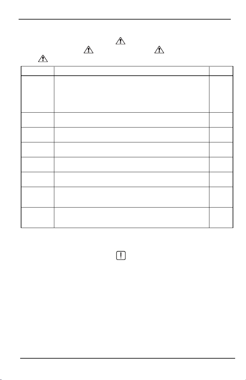
Welcome Screen
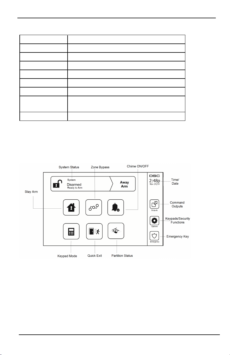
The date and t ime are displayed in the upper right corner of the screen. The system status (i.e., Ready, Armed, Exit
Delay etc.) is displayed at the top of the screen.
Figure 2- Welcome Screen
0°C to +49°C (32°F to 120°F)
93% (max) relati ve humidity non-condensing
- 8 -
Page 9
Emergency Keys
Emergency Keys
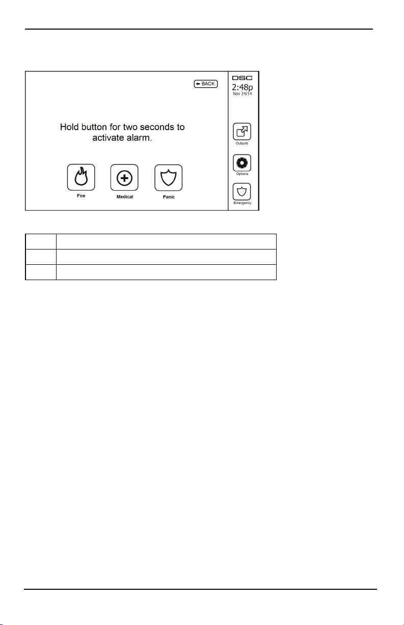
Figure 3- Emergency Screen
When the emergency key is pressed, a new screen is displayed with:
Fire Fire Assistance Required. Press and hold for 2 seconds to activate.
Medical Medical Assist ance Required. Press and hold for 2 seconds to activate.
Panic Police Assistance Required. Press and hold for 2 seconds to activate.
Important: The Medical and Panic keys are ON by default. The Fire key will not function unless programmed by
the Installer. Please ask your installer if the Fire, Medical and Panic keys are enabled.
Note: These events are recorded in the log.
- 9 -
Page 10
Arming and Disarming the System
Arming and Disarming the System
Stay Arm (Arming the Perimeter)
Ask your alarm company if this function is available on your system.
Stay arming bypasses the interior protection (i.e., motion sensors) and arms the perimeter of the syst em (i.e., doors
and windows). Close all sensors (i.e., stop motion and close doors). The Ready ( ) indicator should be on. Press
the Stay Arm button and/or enter your Access Code and do not leave the premises (if your installer has pro-
grammed this but ton). During exit delay, the Armed ( ) and Ready( )indicators turn on to visually indicate
that the system is arming.
When the exit delay expires, the Ready LED turns off, the Armed LED remains on and the keypad stops sounding
to indicate that the alarm system is armed.
Note: For SIA FAR listed panels, the Stay Arming exit delay will be twice as long as the Away Arming exit
delay.
Silent Exit Delay
If the system is armed using the Stay Arm button or using the "No Entry" Arming method ([*][9][access code], the
audible progress annunciation (keypad buzzer) is silenced and the exit time doubled for that exit period only (CP01 versions only).
Note: For non CP-01 versions, Standard exit time is used.
When Stay Arm is selected from the Home screen:
l The display indicates “Exit Delay in Progress,” and t he pre-programmed exit delay begi ns.
l The Armed LED Indicator turns on.
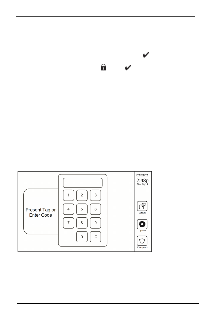
If Quick Arm is not enabled by the installer, then a numerical keypad is displayed (see following figure). Enter a
valid access code to proceed.
Figure 4- Keypad
If Disarm is selected during the exit delay, a numeric keypad is displayed.
l Enter (tap) your access code.
l The arming sequence is aborted and the syst em returns to the Home screen.
l The Armed LED turns OFF.
At the end of the pre-programmed exit delay:
- 10 -
Page 11

Arming and Disarming the System
l The Disarm screen is displayed.
l The Ready Indicator turns OFF.
l “Stay Armed-Bypass” is displayed in the Status Bar.
Note: This screen will go into stand-by mode after 15 minutes. Tap the screen to restore the display.
Disarm
If Disarm is selected:
l A numerical keypad is displayed.
l Enter your Access Code in the keypad.
l The system returns to the Home screen and the red Armed indicator turns OFF.
l The alarm status is momentarily displayed in the status bar, then "Ready" i s displayed.
l The green Ready indicator turns ON.
Note: If your code is invalid, the system will not disarm and a 2-second error tone will sound. If this happens,
press # and try again.
Away Arm
When Away Arm is selected:
l Enter a valid access code t o proceed.
l The Armed LED Indicator turns ON.
l "Exit Delay in Progress" i s displayed in the Status Bar. The pre-programmed exit delay begins.
l The touchscreen "beeps" at a 1-second urgency interval during the exit delay. Then 3 beeps sound in the
last 10 seconds.
Note: If Quick Arm is not enabled by the i nstaller, a numerical keypad is displ ayed.
If Disarm is selected during the exit delay:
l A numeric keypad is displayed. Tap your access code.
l The Arming sequence is aborted and the system returns to the Home screen.
l The Armed LED turns OFF.
At the end of the pre-programmed exit delay:
l The Disarm screen is displayed.
l The Ready Indicator turns OFF.
l "Away Armed" is displayed in the Status Bar.
Exit Delay Time Restart
The control panel provides an option where if an entry/exit zone is tripped, a second time prior to the end of the
exit delay, the exit delay time restarts. The exit delay timer can only be restarted once.
Alarm Cancel Window
The control panel provides a period of time in which the user can cancel the alarm transmission. The minimum duration of this ti me is five minutes. If the programmed alarm transmission delay has expired, canceling an alarm
sends a message to the monitoring station. Upon a successful transmission of the cancelation message, the keypad
will beep 6 ti mes.
- 11 -
Page 12

Arming and Disarming the System
Bell/Siren Sounds After Away Arming
Audible Exit Fault
In an attempt to reduce false alarms, t he Audible Exit Fault is designed to not ify you of an improper exit when
arming the system in the Away mode. In the event that you fail to exit the premises during the allotted exit delay
period, or if you do not securely close the Exit/Entry door, the system will notify you that it was improperly
armed in two ways: the keypad will emit one continuous beep and the bell or siren will sound.
Your installer will tell you if this feature has been enabled on your system. If this occurs:
1. Re-enter t he premises.
2. Enter your access code to disarm the system. You must do this before the entry delay timer expires.
3. Follow the Away arming procedure again, making sure to close the entry/exit door properly.
Arming Error
An error tone will sound if the system is unable to arm. This will happen if the system is not ready to arm (i.e.,
sensors are open), or if an incorrect user code has been entered. If this happens, ensure all sensors are secure. Press
[#] and try again, ensuring that a valid access code is entered. Please check with your installer to determine if arming is inhibited by any other means.
Remote Arming and Disarming
The system can be armed and/or di sarmed using the remote wireless key or proximity tag. When arming the system by using the Arm button on the wireless key, the syst em will acknowledge the command by sounding a
single bell squawk (if bell squawk is enabled). When disarming using the Disarm button on the wireless key, the
system will acknowledge the command by sounding two bell squawks (if bell squawk is enabled) that can be
heard from the exterior of the premises.
To arm the system with a proximity tag:
l Present your proximity tag to a keypad equipped wit h a proximity sensor anytime the syst em Ready
indicator is on.
l If configured by your installer, enter your access code.
To disarm the system with a proximity tag:
l Present your proximity tag to a keypad equipped wit h a proximity sensor anytime the syst em is armed.
(Armed indicator is on) and i f configured as required, enter your access code.
l If you walk through the entry door the keypad will beep. Present your Proximity tag within ____
seconds to avoid an alarm condition.
Using Your System
This section provides additional information about how to use your alarm system.
When Alarm Sounds
The system can generate 3 different alarm sounds:
l Temporal/pulsed siren = Fire Alarm
l 4 beeps, 5-second pause, 4 beeps = Carbon Monoxide Alarm
l Conti nuous siren = Intrusion (Burglary Alarm)
Note: The priority of signals is fire alarm, carbon monoxide alarm and medical alarm, then burglary alarm.
Note: Medical alarm is silent. It only results in an alarm transmissi on to the monitoring station.
Intrusion (Burglary) Alarm Continuous Siren
If you are unsure of the source of the alarm, approach with caution! If the alarm was accidental,
enter your Access Code to silence the alarm. Call your central station to avoid a dispatch.
- 12 -
Page 13

Arming and Disarming the System
If the Intrusion Alarm was Accidental
1. Enter your Access Code to silence the alarm. If the code is entered within 30s (or the programmed value of
the alarm transmission delay) the transmission of the alarm to the monitoring station will be canceled.
2. Call your central stati on to avoid a dispatch.
Fire Alarm Pulsed Siren
Follow your emergency evacuation plan immediately!
If the fire alarm was accidental (e.g., burned toast, bathroom steam, etc.), enter your Access Code to silence the
alarm. Call your central station to avoid a dispatch. Ask your alarm company if your system has been equipped
with fire detection. To reset the detectors, see the Sensor Reset section.
Wireless Carbon Monoxide Alarm
Activation of your CO alarm indicates the presence of carbon monoxide (CO), which can be fatal. During an alarm,
the red LED on the CO detector flashes rapidly and the buzzer sounds with a repeating cadence of: 4 quick beeps,
5-second pause, 4 quick beeps. Also, during an alarm, the siren connected t o the control panel produces a repeating cadence of 4 quick beeps, 5-second pause, 4 quick beeps. The keypad will also provide audible and visual
indication of the CO alarm.
If an Alarm Sounds:
1. Operate silence button.
2. Call emergency services or your fire department.
3. Immediately move outdoors or to an open door/window.
Warning: Carefully review your Carbon Monoxide Installation/User Guide to determine the necessary actions
required to ensure your safety and ensure that the equipment is operating correctly. Incorporate the steps outlined
in the guide i nto your evacuation plan.
- 13 -
Page 14
Troubles
Troubles
When a trouble condition is detected, the Trouble ( ) or System indicator will turn on, and the keypad will
beep every 10 seconds. Press the ( ) key to silence the beeps. Press ( ) to view the trouble condition. The
Trouble ( ) or System indicator will flash. The corresponding trouble will l ight up.
Troubles Comments Action
Service
Required (Press
for more
details)
AC Loss
Phone Trouble The system has detected that the telephone line is disconnected.
Communication
Failure
Zone Fault
Zone Tamper
Wireless Low
Battery
Loss of Clock
Low Battery General System Supervision
Bell Circuit RF Jam Detected
General System Trouble Panel Low Battery
General System Tamper Panel AC Loss
If the building and/or neighborhood has lost electrical power, the syst em will
continue to operate on battery for several hours.
The system attempted to communicate with the monitoring station, but failed.
This may be due to Telephone Line Fault.
The system is experiencing difficulties with one or more sensors on the system.
Press to display the zone.
The system has detected a tamper condition with one or more sensors on the system. Press to display the zone.
The system has detected a low battery condi tion with one or more modules/sensors on the system. Press to display the zone, keypad, wireless key(s) and
RF Delinquency low battery conditions. Press again to see zone troubles.
If complete power was lost (AC and Battery), the time and date will need to be
reprogrammed.
Call for
service
Call for
service
Call for
service
Call for
service
Call for
service
Call for
service
Call for
service
Reprogram
Time &
Date
Alarm Memory
When an alarm occurs, the Alarm indicator flashes.
To view which sensor(s) generated the alarm, press Alarms.
The sensor number where the alarm occurred will be displayed (e.g., zone 3). Use the [<][>] scroll keys to view the
sensors in alarm memory. Press Back or Home to exit. To clear the memory, arm and disarm the system. If an alarm
sounded while armed, the keypad will automatically go to alarm memory when you disarm the system. In this
instance, you should approach with caution, as the intruder may still be within the building/premises.
- 14 -
Page 15
Troubles
Figure 5- Alarms in Memory
Sensor Reset
Certain sensors, after having detected an alarm condition, require a reset to exit the alarm condition (e.g., glass
break sensors, smoke detectors, etc.). Ask your alarm company if this function is required on your system.
To reset the detectors, press t he Reset (Command Output 2 if the installer did not program a label) button on the
Outputs screen. If a sensor fail s to reset, it may still be detecting an alarm condition. If the sensor reset is successful, the alarm is canceled. If unsuccessful , the alarm will reactivate or conti nue.
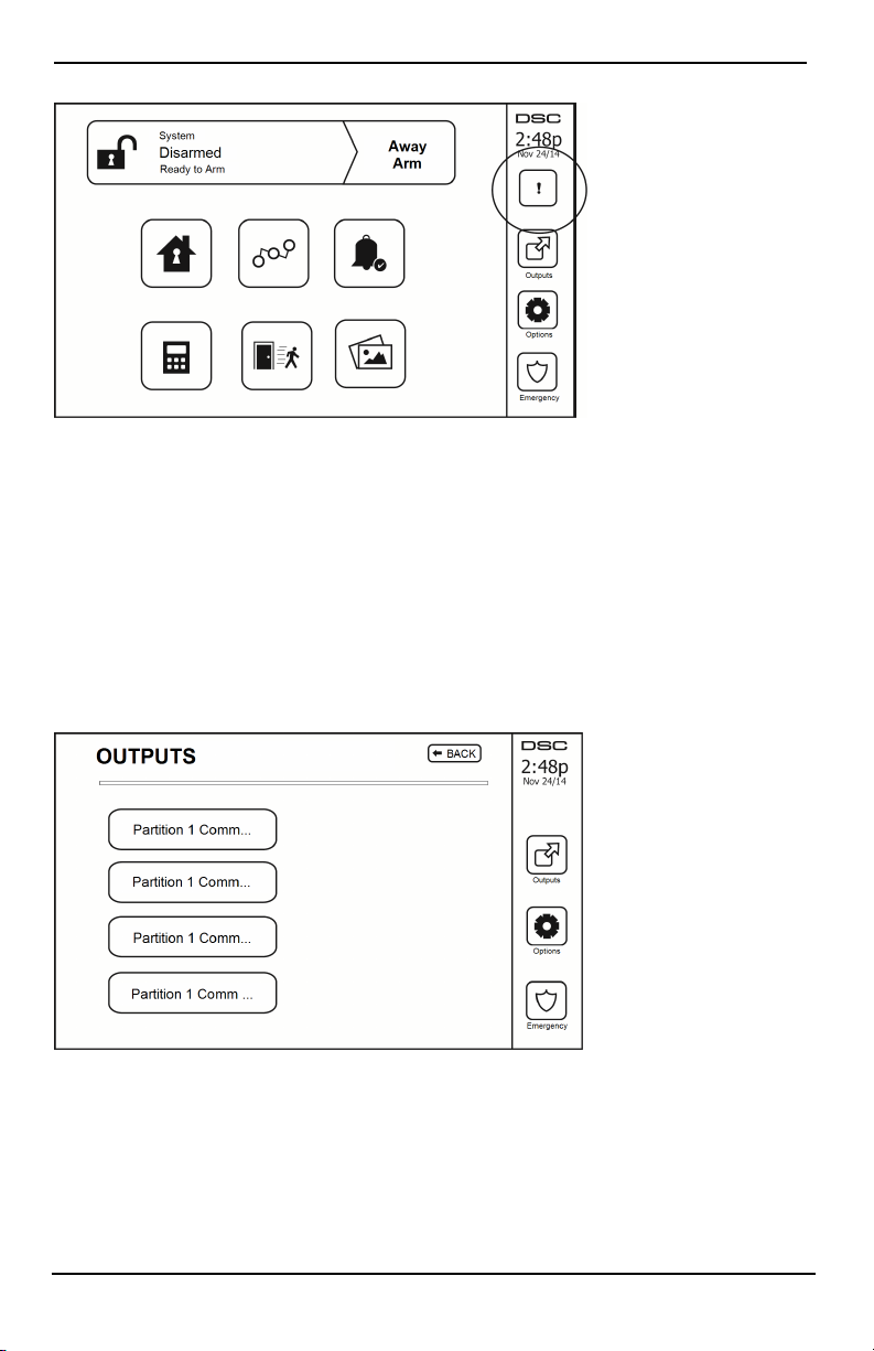
Outputs
Your installer may have programmed these keys to perform various functions (reset smoke detector after an alarm,
open your garage door, etc.) To activate these functions, press Output and then press the appropriate option. For
additional information, refer to the section: Sensor reset.
Figure 6- Outputs
- 15 -
Page 16

Additi onal Functions
Additional Functions
Photos
You can create a slideshow of photos to View on the keypad. Photos are added using an SD card (32x24x2.1 mm.
Not supplied).
The photos must be .jpg format and can be up to 1280 x 720 in size. For best results, use 800 x 480 resolution.
Use photo editing software to adjust the size of your photos.
To start the slideshow, set the screen saver to photo mode. The slideshow plays automatically until the timeout is
reached or the screen is touched again.
To add photos:
1. Press Options, User Functions, Keypad Config, Picture Frame, Select Photos. Thumbnail images of the phot os
on your SD card are displayed.
2. Touch an image to add it to the slideshow. Touch it a second time to remove it.
Use the Transition Time slider to program the amount of t ime each photo is on screen, from 5 seconds to 1
minute.
Use the Photo Frame Timeout slider to control how long your slideshow plays for, from 1 minute to 2 hours.
Select Never to keep the slideshow running until the screen is touched.
Note: Maximum of 255 photos are supported.
Quick Exit
If the system is armed and you need to exit, use the quick exit function to avoid disarming and rearming the system. To activate this function, tap the Quick Exit icon. You have 2 minutes to leave the premises through your
exit door. When the door is closed again the remaining exit time is canceled.
Time & Date Programming
Tap on Options. Select User Functions [Master Code] and then select Time & Date. Tap on the section you would
like to change and use the up/down arrows to change time/date. Once done, press Save.
Keypad Mode
This option allows the HS2TCHP E Touchscreen to function as a traditional DSC keypad.
Door Chime (Chime enable/disable)
The keypad indicates the current state of the door chime function (Enabled or Di sabled). To choose the opposite
function, tap the 'Chime' icon. Three beeps indicate that the chime is ON (Enabled). One long beep indicates that
chime is OFF (Disabled).
Note: The door chime feature should be used in Disarmed mode only.
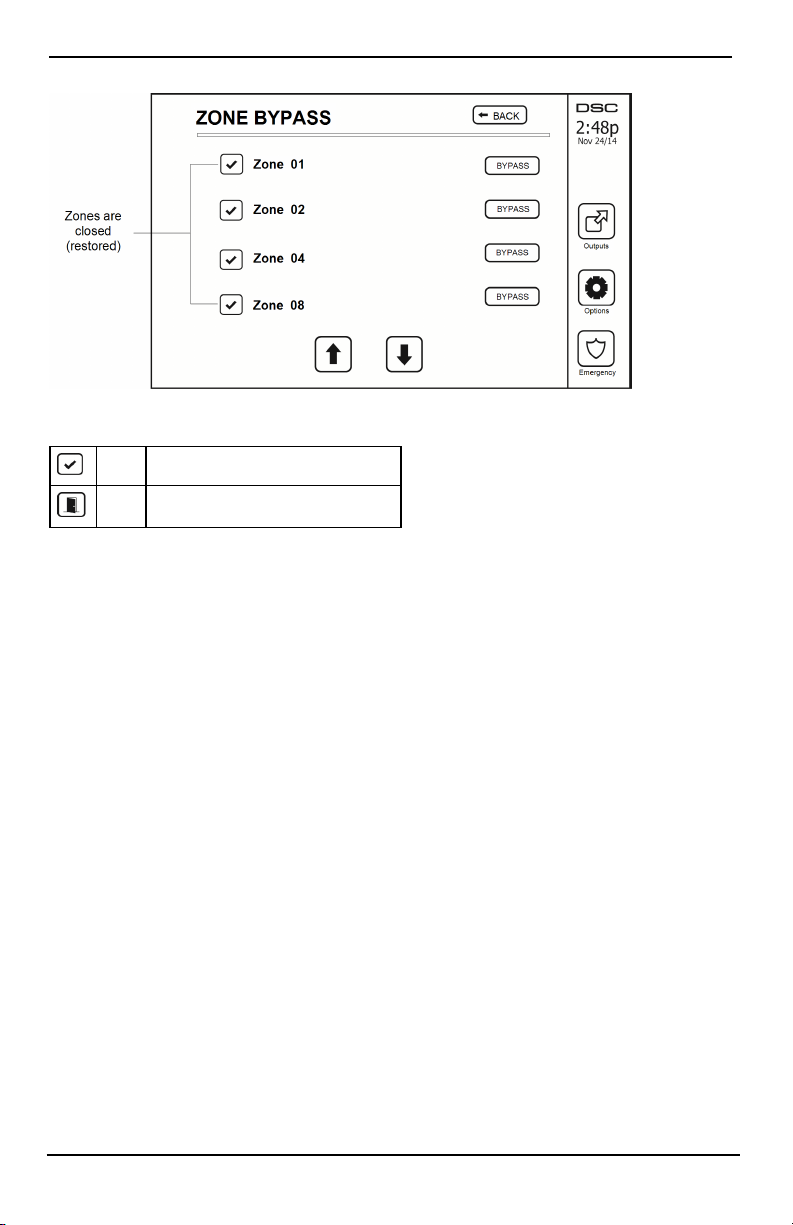
Zone Bypass
This screen allows you to view the status of the zones on the system.
- 16 -
Page 17
Options Menu
Figure 7- Zone Closed
Zone Status Indicators
Ready Zone is closed
Open The zone is open and needs to be closed
Bypassed Zones
Use the zone bypass feature when a zone is open but the system needs t o be armed. Bypassed zones will not cause
an alarm when opened. Bypassing zones reduces the level of security. If you are bypassing a zone because it is not
functioning, call a service technician immediately so that the problem can be resolved and your system returned to
proper working order.
Ensure that no zones are unintentionally bypassed when arming your syst em. Zone bypassing can only be performed while the system is di sarmed. Bypassed zones are automatically canceled each time the system is disarmed
and must be bypassed again, if required, before the next arming.
Note: 24-hour zones can only be unbypassed manually.
Note: For security reasons, your installer has programmed the system to prevent certain zones from being
bypassed. (e.g., smoke detectors).
Bypassing Zones with a HS2TCHP
When in the Zone Status page, scroll up/down through the desired zones, and tap on the bypass icon to bypass
the zone. To unbypass a zone, tap the unbypass icon.
Note: For UL listed installations, zones can only be bypassed manually.
Options Menu
Access the following functions by pressing Options on the right side of the home page. See the online HS2TCHP
E User Manual for more information.
l Access Codes
l Installer Menu
l User Functions
l Chime Enabled/Disabled
l Partition Status
l Keypad Mode
- 17 -
Page 18

Options Menu
Figure 8- Options
Access Codes
When Access Codes is selected from the Options menu, the keypad prompts for a Master Code. When a valid
Master Code is entered, a numeric keypad is displ ayed with arrows to scroll t hrough the list of users. Press the
Select butt on to enter the user options.
Set Access Code: adds/edits the 4-digit or 6-digit code
Set Partitions: assigns the user to partitions
User Options: enables/disables different opt ions for the user
Delete User: deletes the user from the system
The access codes have programmable attributes which allow zone bypassing, or one-time use activation.
Master Code (Access Code 01): The master code, if programmed, can only be changed by the install er.
Supervisor Codes: These codes can be used t o program additional codes which have equal or lesser attributes.
Once programmed, the supervisor codes receive the master code’s attributes. These attributes are changeable. Any
user code can be made a supervisor code by enabling User Code Attribute 1 (see t he following for details).
Duress Codes: Duress codes are standard user codes that transmit the Duress Reporting Code when entered to
perform any function on the system. Any user code can be made a duress code by enabling User Code At tribute 2
(see the following for details).
Note: Duress codes are not valid when entering User Programming, Master Functions or Installer’s sections.
Note: Access codes cannot be programmed as a dupl icate or as a “Code +/- 1”.
Assign Proximity Tags
Depending on how your keypad is programmed, proximity tags can be used to either arm/disarm the system or to
perform a programmed function (e.g. unlock a cabinet or storeroom door). Present the tag to the tag reader.
1. Press [*][5]Master/Supervisor Code].
2. Enter a 4-digit or 6-digit user code.
3. Press 2.
4. Pass the enrolled tag near the tag reader.
Delete Proximity Tags
To delete a proximity tag:
1. Select Options, Access Codes [enter Master code].
2. Select a user to delete.
- 18 -
Page 19

Options Menu
3. Select Prox Tag Prog then delete.
User Code Attributes
1. The default attribut es of a new code will be the att ributes of the code used to enter User Programming
whether it is a new code or an existing code being programmed.
2. System Master Code 01 has partition access for all partitions, as well as attributes 3-4 ON by default.
Note: These attributes are not changeable.
Inherent Attributes (all codes except installer and maintenance)
Arm/Disarm: Any access code with partition access enabled will be valid for arming and disarming that par-
tition.
Command Outputs ([*][7][1], [*][7][2], [*][7][3], and [*][7][4]): If these outputs require access code
entry, any Access Code with partition access will be valid for performing the command output functions on that
partition.
Programmable Attributes
1. Supervisor Code 5. For Future Use
2. Duress Code 6. For Future Use
3. Zone Bypassing Enabled 7. Bell Squawk upon Arming/Disarming
4. Remote Access 8. One Time Use Code
Bell Squawk Attribute
This attribute is used to determine whether an access code should generate an arming/disarming Bell Squawk upon
entry of the code for Away arming. The wi reless keys with access codes associated with them may generate Arming/Di sarming Bell squawks. If desired, this option may be used wit h codes that are manually entered. Please contact your installer to have this programmed.
Note: The Master Code cannot use the Bell Squawk attribute, but is required to enable it for other codes.
Note: This feature cannot prevent the Arming/Disarming squawks from being generated if an access code assigned
to a wireless key is manually entered at a keypad.
Note: This feature is used to annunciate fire trouble signals and also trouble conditions for medical applications.
Partition Assignment
1. This secti on is used to assign users to available partitions. To assign partitions:
2. Select Options > Access Codes.
3. Enter the master code.
4. Select a user.
5. Select Partiti on Attributes.
6. Select the partition(s) to assign to t he user.
Notes on Access Codes andProgramming
l The master code’s attributes cannot be changed.
l When a new code is programmed in User Programming it will be checked against all other codes in the
system. If a duplicate code is found, an error tone is given and t he code is returned to what it was before
it was changed. This applies to both 4 and 6-digit codes.
Erasing an Access Code
To erase a code, select the code and choose Delete User. The system will delete the code immediately and the user
will be returned to select another code.
Installer Menu
These functions are for the installer’s use only.
- 19 -
Page 20

Options Menu
User Functions
First disarm the system then enter Options, User Functions, then Master Code. This command is used to gain
access to the following list of master functions of the system:
Time and Date
Enter desired time and date.
Auto-Arm Time
The system can be programmed to arm at a programmed time each day, per partition. Upon entry of this section,
enter the desired Aut o-Arm time for each day of the week.
At the selected Aut o-Arm time, the keypad buzzers will sound for a programmed amount of time (programmable
by the installer only) to warn that an auto-arm is in progress. The bell can also be programmed to squawk once
every 10 seconds during this warning period. When the warning period is complete, the system will arm with no
exit delay and in Away mode.
Auto-Arming can be canceled or postponed by entering a valid access code only during the programmed warning
period. Auto-Arming will be attempted at the same time the next day. When the Auto-Arming process is canceled
or postponed, the Auto-arm Cancelation Reporting Code will be transmitted (if programmed).
If arming is inhibited by one of the following, the Auto-Arm Cancelation transmission will be communicated:
l AC / DC Inhibit Arm
l Latching System Tampers
l Zone Expander Supervisory Fault
Note: For UL/ULC listed installations, the auto-arm feature shall be canceled when there are zones in an off-normal condit ion.
Enable DLS/Allow System Service
If enabled, the inst aller will be able to access Installer Programming via remote (DLS). The DLS window will
remain open for 6 hrs, during which time the installer will be able to enter DLS an unlimited number of times.
After the 6-hr window has expired, Installer’s Programming will be unavailable again until the window is reopened.
Event Buffer
l Displays the date, ti me and the full description of the event
l The Log is organized from the most recent event (Top) to past events (Down)
l The Left arrow scrolls forward in time
l The Right arrow scrolls back in time
l The Back returns you to the Home screen
l This screen will ti me out to the Home screen after 30 seconds of inactivity
System Test
The system’s bell output, keypad lights and communicator are tested. This test will also measure the panel’s
standby battery.
Important:
l To ensure that your system continues to function as intended, you must test your system weekly.
l For UL HOME HEALTH CARE list ed appli cations, the system shall also be tested weekly without AC
power. To remove AC from the control unit, remove the screw from the restraining tab of the plug in
adapter and remove the adapter from the AC outlet. After completing the test of the unit using only the
battery backup source, reconnect the plug in adapter and attach the screw through the restraining t ab, so
that the adapter is securely attached to the outlet.
l Should your system fail to function properly, contact your installation company immediately.
- 20 -
Page 21
Options Menu
l All smoke detectors must be tested by your smoke detector installer once a year to ensure proper oper-
ation.
Auto-Arm/Disarm Control
Pressing Auto-Arm while in the User Function menu will enable (three beeps) or disable (one long beep) the
Auto-Arm and Auto-Disarm feature, by partit ion. With this feature enabled, the panel will automatically arm in
Away mode (Stay/Away zones active) or disarm at the same time each day. The Auto-Arm time is programmed
with the Auto-Arm time button. Auto-Disarm must be programmed by the system installer.
User Call-up
This option gives your service provider temporary access to the alarm control panel for remote servicing.
Engineer's Reset
If an alarm has occurred on your system, the system will not allow you to rearm (Ready light is OFF). You will
need to contact your installer. They will check and reset the system for you. This may involve a visit to check
your system. After the reset is performed, your system will function properly again.
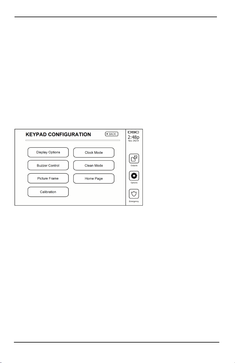
Keypad Configuration
Figure 9- Keypad Configuration
Display Options: sets the bright ness and screen timeout of the Touchscreen, as well as screen saver options.
Buzzer Control: sets the buzzer volume of the Touchscreen. Note: For SIA CP-01, the buzzer volume shall not
be placed at the minimum setting.
Note: For UL/ULC installations, the buzzer level shall not be changed from the default level.
Picture Frame: selects the pictures that will be displayed on the slideshow.
Calibration: calibrates the Touchscreen.
Clock Mode: displays the digital clock.
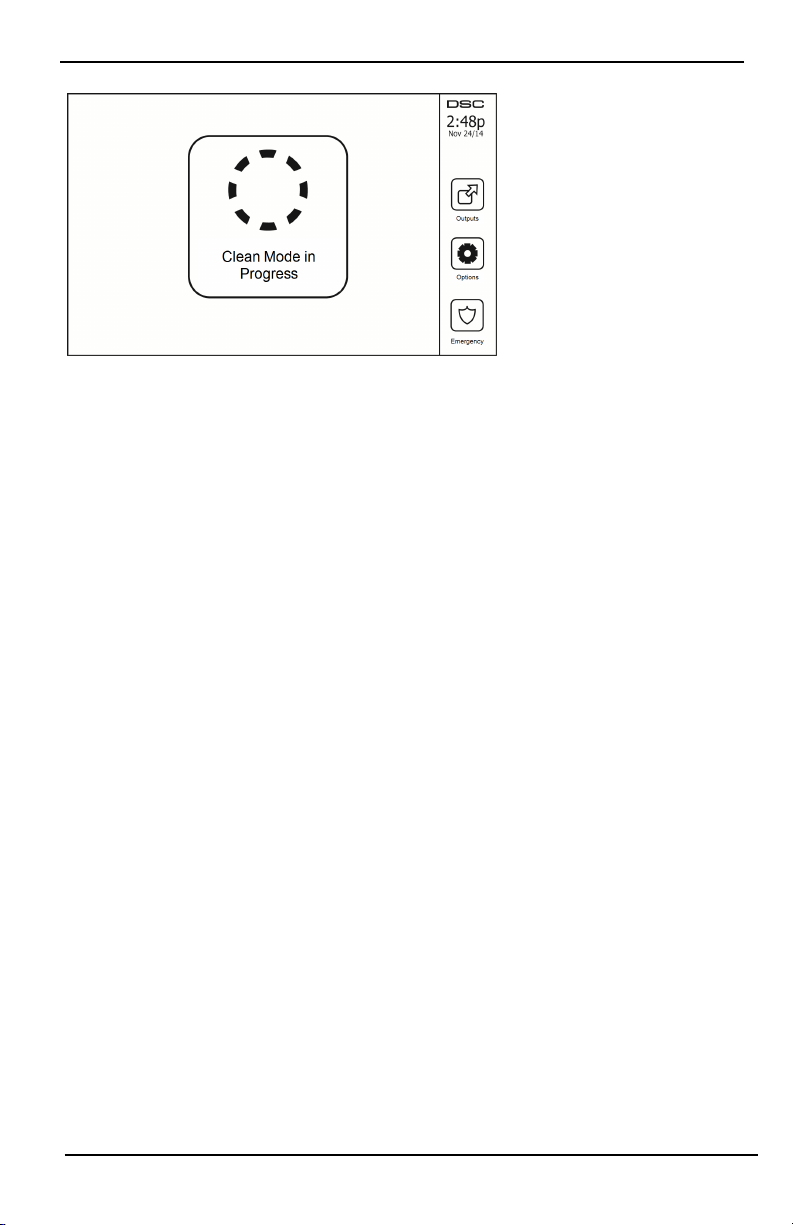
Clean Mode: allows the user to touch (i.e., clean) the screen without enabling or disabling any functions. The
screen will remain in thi s mode for 30 seconds, then return to the Keypad Configuration screen.
- 21 -
Page 22
Options Menu
Figure 10- Clean Mode
Home Page: can be configured in one of two different views, Classic (square buttons) and Contemporary
(rondel).
Chime Enabled/Disabled
Door Chime: To turn the door chime function On/Off, tap the Chime icon. 3 beeps indicate that the chime is
ON. 1 long beep indicates the Chime is OFF.
Arming
Stay Arm: arms the system in Stay mode
Away Arm: arms the system in Away mode
Night Arm: To fully arm the system when it has been armed in Stay Mode, press Night Arm button. All interior
zones will now be armed except for devices programmed as Night Zones. Night zones are only armed in Away
mode. This permits l imited movement within the premises when the system is fully armed. Ensure that your
installer has provided you with a list identifying zones programmed as night 18 zones. When the interior zones
have been activated (i.e., Night Arm), you must enter your access code to disarm the system to gain access to
interior areas that have not been programmed as night zones.
Quick Exit: refer to the section: Quick Exit
Global Away Arm: arms all partitions to which the User Code is assigned, in Away mode.
Global Stay Arm: arms all partitions to whi ch the User Code is assigned, in Stay mode.
No Entry Arm: arms the system with no entry.
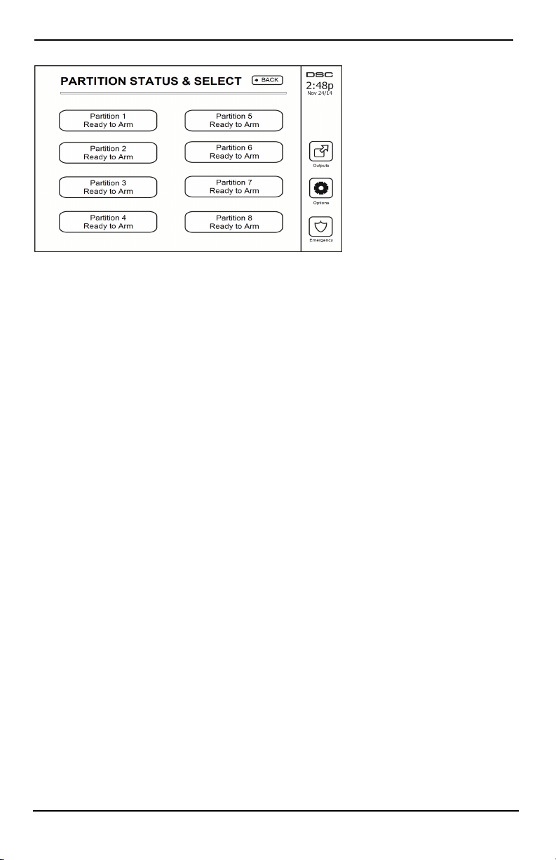
Partition Status
To view the partition status, press Options, User Functions, then Partition Status. The keypad shows basic status
for up to 8 partitions, depending on the configuration of your system. Each partition is identified along with its
current status.
- 22 -
Page 23
Managing Partitions
Figure 11- Partition Status
Keypad Mode
This option allows the HS2TCHP E Touchscreen to function as a traditional DSC keypad.
Managing Partitions
A partition is a limited area of t he premises which operates independently from the other areas. Partitioni ng a system can be beneficial if the property has outbuildings that need to be secured independently of a main area or if
the home has a separate apartment. Each partition can have its own keypad, or a keypad can have access to all partitions. User access to partitions is controlled via access code. A master code can access the entire system and partitions, while a user code is limited to assigned partitions.
Partitions
Keypads can be configured to control an individual partition or all partitions.
Note: Access t o this feature must be configured by your installer.
Single Partition Operation
Single partition keypads provide access to alarm functionality for an assigned partition.
Single partition keypads behave as follows:
l Displays the armed set state of the partition.
l Displays open zones, if assigned to the partition the keypad is on.
l Displays bypassed zones and allows zone bypassing or creating bypass groups of zones assigned to the
keypad partition.
l Displays system troubles (system low battery, system component faults/tampers).
l Displays alarms in memory that occurred on the partition.
l Allows the door chime to be Enabled/disabled.
l System test (sounds bells/PGMs assigned to the partition).
l Label programming (zone, partition and user labels for the partition).
l Command output controls (outputs assigned to the parti tion, or global outputs such as smoke detector
reset).
l Temperatures.
Loaning a Keypad to Another Partition
The HS2TCHP Touchscreen Keypad can be loaned to operate on other parti tions. When a keypad is loaned to
another partition, it wi ll behave on the loaned partition as if it was originally assigned there. An access code must
be entered before loaning a keypad to another partition. An access code is also required to perform any function
on that parti tion.
To loan a keypad to another partition:
- 23 -
Page 24
Managing Partitions
1. Select Options > Partition Status.
2. Enter your access code.
3. Select the partition to loan the keypad to. If the keypad is inactive for more than 30 seconds, it will
return to its original partition.
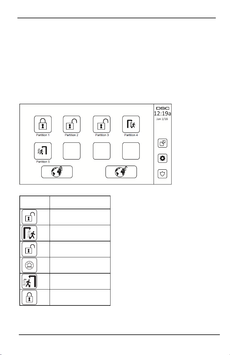
Global Keypad Operation
Once a valid access code is entered, a global keypad will display the status of any partitions that the user has permission to view. From this overview, you can loan the global keypad to a partition, arm all partitions or disarm
all partitions. The status of each partition will be identified by a partition status icon. For an explanation of partition status icons, see the table below. The global arm and global disarm buttons will arm or disarm all displayed
partitions.
To Loan a Global Keypad to Another Partition:
1. Select Partiti on Status.
2. Select the partition to loan the keypad to.
Figure 12- Global Keypad Mode
Partition
Status Icon
Description
GREEN BACKGROUND
Partition is ready to be armed
Partition is in exit delay
GRAY BACKGROUND
Partition is not ready to be armed
Partition is in alarm
Partition is in entry delay
Partition is armed
- 24 -
Page 25

Managing Partitions
Fire and CO Zone Types
l If a Fire zone generates an alarm only the partition the fire zone is assigned to will go into alarm. Other
partitions retain their current state.
l If the [F] key on a global keypad is used to generate an alarm all enabled partitions will go into alarm.
l One or more fire keypads may be located on any partition.
l On alarm, the fire auto-scroll display appears on all partition keypads and on all global keypads. Fire
alarm silence and fire system reset may be done directly on any partition keypad. To silence a fire or CO
alarm from a global keypad requires that the global keypad be loaned to one of the partitions.
- 25 -
Page 26

SMS Command and Control
SMS Command and Control
SMS Command and Control allows you t o send text messages to your system, enabli ng the system to perform certain actions. For a list of commands and how to send them see the SMS Commands table. As a security measure,
only authorized phone numbers can interact with your system. Messages from all other phone numbers will be
rejected.
Note: This is a supplementary feature that has not been investigated by UL/ULC. Must be enabled and configured
by your installer.
Looking up the Number to Call for SMS Commands
The phone number of the system is set at the time of installation. To quickly find the phone number perform the
following steps.
1. Select User Functions > SMS Programming
2. Using t he downward pointing arrow, scroll to Phone #9
3. The number programmed in Phone #9 is the phone number of the system. Send SMS commands to this
number to interact with your system.
Authorizing User Phones to Send SMS Commands
You can authorize up to eight phone numbers to int eract with your system with SMS. Before the system will
accept an incoming SMS command, you must enter the sending phone number.
To authorize a phone for SMS Commands:
1. Select User Functions > SMS Programming
2. Using t he up and down pointing arrows, scroll to an empty phone number and select it
3. Using t he numerical pad, enter the phone number of the phone you want to authorize and press Save.
Sending SMS Commands to your System
In order to successfully send commands to your system from your cellphone, you must send SMS messages in the
proper format. If configured, commands require the inclusion of a User Access Code in your message. The access
code will be verified by the system before executing any commands.
Additi onal information about sending SMS commands:
l Text messages are not case sensitive and extra spaces are ignored.
l In multi-partition systems and if the User has rights to manage the desired partitions, commands can be
sent to specific partitions by including the partition number. For more information on partitions see:
"Managing Partitions".
l If the panel is configured to require an Access Code and the code is not sent or is invalid, the panel will
send a notification to the user advising the command was unsuccessful.
The following table list s all available SMS commands with examples of how to enter the Partition number and
access codes. The format for entering commands is as follows:
Note: Verify with your installer that the Partition number and access code are required in your SMS message. If
one or both are not required, do not enter them in your SMS message.
Note: Responses to Status and Alarm Memory requests may require more than 1 SMS message, depending on
status of t he system. There is a 10 second delay between transmission of SMS messages.
- 26 -
Page 27

SMS Commands
Commands Notes
Stay ArmSet Stay armssets the system
Away ArmSet Away armssets the system
Night ArmSet Night armssets the system
DisarmUnset DisarmsUnsets the system
Activate Command Output 1 Activates Output 1
Activate Command Output 2 Activates Output 2
Activate Command Output 3 Activates Output 3
Activate Command Output 4 Activates Output 4
Deactivate Command Output 1 Deactivates Output 1
Deactivate Command Output 2 Deactivates Output 2
Deactivate Command Output 3 Deactivates Output 3
Deactivate Command Output 4 Deactivates Output 4
Bypass 001 Bypasses specified zone number
Unbypass 001 Clears the bypass from the specified zone number
Omitting the partition number causes the syst em to
Status Request
Alarm Memory Request
Help
send a status report for all partitions. To request a
status report for a specific partition enter the appropriate partition number.
Omitting the partition number causes the syst em to
send a status report for all partitions. To request a
status report for a specific partition enter the appropriate partition number.
The Help command generates an SMS response li sting all Interactive commands that can be sent to
the module. Access Code is not required.
Page 28

Testing Your System
Note: If you are going to perform a System Test, call your Monitoring Station to inform them when you begin and
also when you end the test.
Testing Your Keypad Sounder and Siren
The System Test performs a two-second check of the keypad sounder and bell or siren, in addition to testing the
keypad status lights and the panel backup battery.
1. Press Options, User Functions [Master Code], then System Test. The following will occur:
- The system activates all keypad sounders and bells or sirens for 2 seconds. All keypad lights turn ON.
- The Ready, Armed, and Trouble LEDs will flash for the duration of the test.
2. To exit the function menu, press [#].
Testing Your Entire System
All smoke detectors in this installation must be tested by your smoke detector installer or dealer once a year to
ensure they are functioning correctly. It is the user’s responsibility to test the system weekly (excluding smoke
detectors). Ensure you follow all the steps i n the “Testing Your Keypad Sounder and Siren” section.
Note: Should the system fail to function properly, call your installation company for service i mmediately.
1. Prior to testing, ensure that the system is disarmed and the Ready light is on.
2. Close all zones to return the system to the Ready state.
3. Perform a System Test by following the steps in the “Testing Your Keypad Sounder and Siren” section.
4. To test the zones, activate each detector in turn (e.g., open each door/window or walk in motion detector
areas).
On an HS2TCHP E keypad, the following message will be displayed when each zone (detector) is activated:
“Ready to Force,” “Not Ready”. Use the zone status button to view which zones are open. The message will disappear when the zones are closed.
Note: Some features described above will not be functional unless enabled by your installer. Ask your installer
which features are functional on your system.
Walk Test Mode
The installer can initiate a Walk Test mode for the syst em. While in Walk Test mode, the Ready, Armed, and
Trouble LEDs will flash t o indicate that Walk Test is active. When the system automatically terminates the Walk
Test mode, it will annunciate with an audibl e warning (5 beeps every 10 seconds), beginning five minutes prior to
the termination of the test.
Allowing Computer Access To Your System
From time to time, your installer may need to send information to or retrieve information from your security system. Your installer will do this by having a computer call your system over the telephone line. You may need to
prepare your system to receive this ‘downloading’ call. To do this, press Options, User Functions [Master Code],
then System Serv/DLS from the Touchscreen. This allows downloading for a limited period of time. During this
time, the system will answer incoming downloading calls. For more information on thi s feature, please ask your
installer.
Page 29

Reference Sheets
Fill out the following information for future reference and store this guide in a safe place.
System Information Enabled?
[F] FIRE [+] Medical [P] PANIC
The Exit Delay Time is ___ seconds
The Entry Delay Time is ___ seconds
For Service
Central Station Information:
Account #: ________________ Telephone #: ________________
Installer Information:
Company #: ________________ Telephone #: ________________
Battery Installation / Service Date:
__________________________
__________________________
__________________________
If you suspect a false alarm signal has been sent to the central monitoring station, call the station to
avoid an unnecessary response.
Page 30

Access Codes (copy as needed)
HS2016/HS2032/HS2064/HS2128 MASTER CODE [01]: ________________________
Code Access Code Code Access Code Code
01 35 69
02 36 70
03 37 71
04 38 72
05 39 73
06 40 74
07 41 75
08 42 76
09 43 77
10 44 78
11 45 79
12 46 80
13 47 81
14 48 82
15 49 83
16 50 84
17 51 85
18 52 86
19 53 87
20 54 88
21 55 89
22 56 90
23 57 91
24 58 92
25 59 93
26 60 94
27 61 95
28 62 96
29 63 97
30 64 98
31 65 99
32 66 100
33 67
34 68
Page 31

Sensor / Zone Information (copy as needed)
Sensor Protected Area Sensor Type
1
2
3
4
5
6
7
8
9
10
11
12
13
14
15
16
17
18
19
20
21
22
23
24
25
26
27
28
29
30
Page 32

Guidelines for Locating Smoke Detectors and CO Detectors
The following information is for general guidance only and i t is recommended that local fire codes and regulations
be consulted when locating and installing smoke and CO alarms.
Smoke Detectors
Research has shown that all hostile fires in homes generate smoke to a greater or lesser extent. Experiments with
typical fires in homes indicate that detectable quantities of smoke precede detectable levels of heat in most cases.
For these reasons, smoke alarms shoul d be installed outside of each sleeping area and on each storey of the home.
The following information is for general guidance only and i t is recommended that local fire codes and regulations
be consulted when locating and installing smoke alarms. It is recommended that additional smoke alarms beyond
those required for minimum protection be installed. Additional areas that should be protected include: the basement; bedrooms, especially where smokers sleep; dining rooms; furnace and utility rooms; and any hallways not
protected by the required uni ts. On smooth ceilings, detectors may be spaced 9.1m (30 feet) apart as a guide. Other
spacing may be required depending on ceiling height, air movement, the presence of joists, uninsulated ceilings,
etc. Consult National Fire Alarm Code NFPA 72, CAN/ULC-S553-02 or other appropriate national standards for
installation recommendations.
l Do not locate smoke detectors at the top of peaked or gabled ceilings; the dead air space in these loc-
ations may prevent the unit from detecting smoke.
l Avoid areas with turbulent air flow, such as near doors, fans or windows. Rapid air movement around
the detector may prevent smoke from ent ering the unit.
l Do not locate detectors in areas of high humidity.
l Do not locate detectors in areas where the temperature rises above 38°C (100°F) or falls below 5°C
(41oF).
Smoke detectors should always be installed in USA in accordance with Chapter 29 of NFPA 72, the National Fire
Alarm Code: 29.5.1.1.
Where required by other governing laws, codes, or standards for a specific type of occupancy, approved single- and
multiple-station smoke alarms shall be installed as follows:
1. In all sleeping rooms and guest rooms.
2. Outside of each separate dwelling unit sleeping area, within 21 ft (6.4 m) of any door to a sleeping
room, with the distance measured along a path of travel.
3. On every level of a dwelling unit, including basements.
4. On every level of a residential board and care occupancy (small facility), including basements and excluding crawl spaces and unfinished attics.
5. In the living area(s) of a guest suite.
6. In the living area(s) of a residential board and care occupancy (small facility).
Page 33

Carbon Monoxide Detectors
Carbon monoxide is colorless, odorless, tasteless, and very toxic. It also moves freely in the air. CO detectors can
measure the concentration and sound a loud alarm before a potentially harmful level is reached. The human body is
most vul nerable to the effects of CO gas during sleeping hours; therefore, CO detectors should be located in or as
near as possible to sleepi ng areas of the home. For maximum protection, a CO alarm should be located outside
primary sleeping areas or on each level of your home. Figure 5 indicates the suggested locations in the home.
Do NOT place the CO alarm in the following areas:
l Where the temperature may drop below -10ºC or exceed 40ºC
l Near paint thinner fumes
l Within 5 feet (1.5m) of open flame appliances such as furnaces, stoves and fireplaces
l In exhaust streams from gas engines, vents, flues or chimneys
l Do not place in close proximity to an automobile exhaust pipe; this will damage the detector
PLEASE REFER TO THE CO DETECTOR INSTALLATION AND OPERATING INSTRUCTION SHEET FOR
SAFETY INSTRUCTIONS AND EMERGENCY INFORMATION.
Page 34

Household Fire Safety Audit
Read this section for i mportant information about fire safety. Most fires occur in the home. To minimize this
danger, we recommend t hat a household fire safety audit be conducted and a fire escape plan be developed.
1. Are all electrical appliances and outlets i n a safe condition? Check for frayed cords, overloaded lighting
circuits, etc. If you are uncertain about the condition of your electrical appliances or household service,
have a professional evaluate these units.
2. Are all flammable liquids stored safely in closed containers in a well-vent ilated cool area? Cleaning with
flammable liquids should be avoided.
3. Are fire-hazardous materials (e.g., matches) well out of reach of children?
4. Are furnaces and wood-burning appli ances properly installed, clean and in good working order? Have a
professional evaluate these appliances.
Fire Escape Planning
There is often very little time between the detection of a fire and the time it becomes deadly. It is thus very important that a family escape plan be developed and rehearsed.
1. Every family member should parti cipate in developing the escape plan.
2. Study the possible escape routes from each location within the house. Since many fires occur at night,
special attenti on shoul d be given to the escape routes from sleeping quarters.
3. Escape from a bedroom must be possible without opening the interior door.
Consider the following when making your escape plans:
l Make sure that all border doors and windows are easily opened. Ensure that they are not painted shut,
and that their locking mechanisms operate smoothly.
l If opening or using the exit is too difficult for children, the elderly or handicapped, plans for rescue
should be developed. This includes making sure that t hose who are to perform the rescue can promptly
hear the fire warning signal.
l If the exit is above the ground level, an approved fire ladder or rope shoul d be provided as well as t rain-
ing in its use.
l Exits on the ground level should be kept clear. Be sure to remove snow from exterior patio doors in
winter; outdoor furniture or equipment should not block exits.
l Each person shoul d know t he predetermined assembly point where everyone can be accounted for (e.g.,
across the street or at a neighbour’s house). Once everyone is out of the building, call the fire department.
l A good plan emphasizes quick escape. Do not investigate or attempt to fight the fire, and do not gather
belongings as this can waste valuable t ime. Once outside, do not re-enter the house. Wait for the fire
department.
l Write the fire escape pl an down and rehearse it frequently so that should an emergency arise, everyone
will know what to do. Revise the plan as conditions change, such as the number of people in the home,
or if there are changes to the building’s construction.
l Make sure your fire warning system i s operational by conducting weekly tests. If you are unsure about
system operation, contact your installer.
l We recommend that you contact your local fire department and request further information on fire safety
and escape planni ng. If available, have your local fire prevention officer conduct an in-house fire safety
inspection.
Page 35

License Agreement
IMPORTANT - READ CAREFULLY: DSC Software purchased wi th or w ithout P roducts and Components is copyrighted and is purchased under the following license
terms:
- This End-User Lice nse Agreement (“EULA”) is a legal agreement between You (the company, individual or entity who acquired the Software a nd any related Hardware)
and Digital Security Controls, a division of Tyco Safety P roducts Canada Ltd. (“DSC”), the manufacturer of t he integrated s ecurity s ystems and the developer of the s oftware anda ny related products or components (“HARDWARE”) which Youac quired.
- If the D SC software product (“SOFTWARE PRODUCT” or “SOFTWARE”) is intended to be accompanied by HARDWARE, and is NOT accompanied by new
HARDWARE, Youmay not use, copy or install the SO FTWARE P RODUCT. The SOF TWARE P RODUCT i ncludes computer s oftware, and may i nclude ass ociated
media, printed materials , and “online” or electronic documentation.
- A ny s oftware provided along with the Software Product that is associated with a separate end-user license agreement is licensed to You under the terms of t hat license
agreement.
- By installing, copying, downloading, storing, accessing or otherwise using the Software Product, You agree unconditionally to be boundby the terms of this EULA, even
if this EU LA is deemed to be a modification of anyprevious arrangement or contract. If Y ou do not agree to the te rms of this EULA, DSC is unwilling t o l icense the S oftware Product t o Y ou, and You have no right to use it.
SOFTWARE PRODUCT LICENSE
The S OFTWARE PRODUCT is protected by copyright laws andi nternational copyright treaties, as well as other intellectual property laws and treaties. The
SOFTWARE PRODUCT is licensed, not s old.
1. GRANTOFLICENSE This EULAgrants Youthe followingrights:
(a)Software Install ation a nd Us e - For each li cense You acquire, You may have only one copy of the SO FTWARE P RODUCT i nstalled.
(b)Storage/Network Us e - The SOFTWARE PRODUCT may not be installed, access ed, displayed, run, shared or us ed concurrently on or from different computers, including a workstation, terminal or other digital electronic device (“Device”). Inother words, if Youhave s everal w orkstations, You will have to acquire a license for each
workstation where the S OFTWARE will be used.
(c)Backup Copy- You may make back-upcopies of t he S OFTWARE PRODUCT, but You may only have one copy per license installed at any given time. Youmay use
the back-up copy s olely for archival purposes. Except as expressl y provided in this EULA, Youmay not otherwise make copies of the SOFTWARE PRODUCT, i ncluding
the printed materials accompanying the SOFTWARE.
2. DESCRIPTION OF OTHER RIGHTS AND LIMITATIONS
(a) Limit ations onReverse Engineering, Dec ompilation and D isas sembly - You may not reverse engineer, decompile, or dis ass emble t he SOFTWARE PRODUCT, except
and only to the extent that such activity is expressly permitted byapplicable law notwithstanding this limitation. Y ou may not make any changes or modifications to the
Software, without the written permission ofan officer of DSC. You may not remove any proprietary notices, marks or l abels from t he Software Product. You shall institute reasonable measures to ens ure compliance with the terms and conditions of this EULA.
(b) Separation of Components - The Software Product is licensed as a si ngle product. Its component parts may not be separated for us e onmore than one H ARDWARE
unit.
(c) S ingle INTEGRATED PRODUCT - If Youa cquired this SOFTWARE with H ARDWARE, t hen the SOFTWARE PRODUCT is licensed wit h t he HARDWARE as
a single integrated product. In this case, the SOFTWARE PRODUCT may only be used w ith the HA RDWARE as set forth in this EULA.
(d) Rental - You may not rent, l ease or lend the SO FTWARE P RODUCT. You may not make it available to others or post it on a server or w eb site.
(e) S oftware P roduct Transfer - You may transfer all of Your rights under this EULA only as part of a permanent s ale or transfer of the HARDWARE, providedY ou retain
no copies, You t ransfer all of the SOFTWARE PRODUCT (including all component parts, the media and printed materials , any upgrades and this EULA), and provided
the recipient agrees to the terms of this EULA. If the SOFTWARE PRODUCT is an upgrade, any transfer must also include all prior versions of the SOFTWARE
PRODUCT.
(f) Termination - Without prejudice to any other rights, DSC may terminate this EULA if You fail to comply wit h t he terms and conditions of this EULA. In s uch event,
You must destroy all copies of the SOFTWARE PRODU CT and all of it s component parts.
(g) Trademarks - This EULA does not grant Youa ny rights in connection wit h a ny trademarks or s ervice marks of DSC or its suppliers.
3. COPYRIGHT
All title and intellectual property rights in and to the SOFTWARE PRODUCT (including but not li mited to any i mages, photographs, andt ext incorporated into the
SOFTWARE PRODUCT), the accompanying printed materials , and any copies of the S OFTWARE PRODUCT, are owned by D SC ori ts suppliers. You may not copy
the printed materials accompanying the SOFTWARE P RODUCT. All title and intellectual property rights in and to the content which may be access ed through use of the
SOFTWARE PRODUCT are the property of t he respective content owner and may be protected by applicable copyright or other i ntellectual property laws and treati es.
This EULA grants Youno rights to use such content. All rights not expressly granted under this EULA are reserved by D SC andi ts suppliers.
4. EXPORT RESTRICTIONS
You agree that Y ou wil l not export or re-export t he SOFTWARE PRODUCT to any country, person, or entity subject to Canadian export restrictions.
5. CHOICE OF LAW
This Software License Agreement is governed by t he l aws of the Province of Ontario, Canada.
6. ARBITRATION
All disputes arising in connection wit h this Agreement shall be determined by final and binding arbitration in accordance with the Arbitration Act, and the parties agree to
be bound by the arbitrator’s decision. The place of arbitration s hall be Toronto, Canada, and the language of the arbitration shall be English.
7. LIMITED WARRANTY
(a) NO WARRANTY - DSC PROVIDES THE S OFTWARE “AS IS” WITHOUT WARRANTY. DSC DOES NOT WARRANT THAT THE S OFTWARE WILL
MEET YOUR REQUIREMENTS OR THAT OPERATION OF THE S OFTWARE WILL BE UNINTERRUPTED OR ERROR-FREE.
(b) CHANGES IN OPERATING ENVIRONMENT - D SC shall not be responsible for problems caused by changes i n t he operating characteristics of the H ARDWARE,
or for problems in the interaction of the SOFTWARE P RODUCT w ith non-DSC-SOFTWARE or H ARDWARE PRODU CTS.
(c) LIMITATION OF LIABILITY - WARRANTY REFLECTS ALLOCATION O F RISK - IN ANY EVENT, IF ANY STATUTE IMPLIES WARRANTIES OR
CONDITIONS NOT STATED IN THIS LICENSE A GREEMENT, DSC’S ENTIRE LIABILITY UND ER ANY PROVISION OF THIS LICENSE A GREEMENT
Page 36

SHALL BE LIMITED TO TH E GREATEROF THE AMOUNT ACTUALLY P AID BY YOU TO LICENSE THE S OFTWARE PRODUCT AND FIVE
29010529R001
CANADIAN DOLLARS (CAD$5.00). BECAUSE SOME JURISDICTIONS DO NOT ALLOW THE EXCLUSION OR LIMITATION OF LIABILITY F OR
CONSEQUENTIAL OR INCIDENTAL DAMAGES, THE ABOVE LIMITATION MAY NOT APPLY TO YOU.
(d) DISCLAIMER OF WARRANTIES - THIS WARRANTY CONTAINS THE ENTIRE WARRANTY A ND SHALL BE IN LIEU O F ANY AND ALL OTHER
WARRANTIES, WHETHER EXP RESSED OR IMPLIED (INCLUDING A LL IMPLIED WARRANTIES O F MERCHANTABILITY O R F ITNESS FOR A
PARTICULAR PURPOS E) AND OF ALL OTHER OBLIGATIONS OR LIABILITIES ON THE PA RT OF DSC. D SC MAKES NO OTHER WARRANTIES. DSC
NEITHER AS SUMES NOR AUTHORIZES AN Y OTHER PERSON PURPORTING TO ACT ON ITS BEHALF TO MODIFY OR TO CHANGE THIS
WARRANTY, NOR TO A SSUME FOR IT ANY OTHER WARRANTY OR LIABILITY CONCERNING THIS SO FTWARE P RODUCT.
(e) EXCLUSIVE REMEDY AND LIMITATION OF WARRANTY - UNDER NO CIRCUMSTANCES SHALL DSC BE LIABLE FOR AN Y SPECIAL,
INCIDENTAL, CONSEQUEN TIAL OR INDIRECT DAMAG ES BASED UPON BREACH OF WARRANTY, BREACH OF CONTRACT, NEG LIGENCE, STRICT
LIABILITY, OR AN Y OTHER LEGAL THEORY. SUCH DAMAGES INCLUDE, BUT ARE NOT LIMITED TO, LO SS OF PROFITS, LOSS OF THE
SOFTWARE PRODUCT OR ANY ASSOCIATED EQUIPMENT, COST OF CAPITAL, COST OF S UBSTITUTE OR REPLACEMENT EQ UIPMENT,
FACILITIES OR SERVICES, DOWN TIME, P URCHASERS TIME, THE CLAIMS OF THIRD P ARTIES, INCLUDING CUSTO MERS, AND INJURY TO
PROPERTY.
WARNING: DSC recommends that the entire sys tem be completely t ested on a regular basis. However, despite frequent t esting, and due t o, but not l imited to, criminal
tampering or elec trical disruption, it i s possible for t his SOFTWARE PRODUCT to fail t o perform as expected.
FCC Compliance Sta tementCAUTION:Changes or modifications not expressly approved by DSC could void your authority to use t his equipment.
This equipment generates and uses radio frequency energy and if not installed andus ed properly, in strict accordance with t he manufacturer’s inst ructions, may cause interference to radio and tel evision reception. It has been type tested a nd foundto comply with the l imits for Class B device i n accordance with the specifications in Subpart
“B” of Part 15 of FCC Rules, which are designed to provide reasonable protection against such interference in any res idential installation. However, t here is noguarantee
that interference wi ll not occur in a particular i nstallation. If t his equipment does cause interference to television or radio reception, which can be determined by t urning the
equipment off and on, t he us er is encouraged to try to correct the interference by one or more of the following measures:
- Re-orient t he receiving antenna
- Relocate the alarm control wit h res pect to the receiver
- M ove the alarm control away from the receiver
- Connect t he alarm control into a different outlet so that alarm control and receiver are on different circuits .
If necess ary, the user should consult the dealer or an experienced radio/television t echnician for additional s uggestions. The user may find the following booklet prepared by
the FCChelpful: “How to Identify and Resolve Radio/ Televis ion Interference P roblems”. This booklet is available from the U.S. Government P rinting Office, Washington, D.C. 20402, Stock # 004-000-00345-4.
This Class B digital apparatus complies with CAN ICES-3(b)/nmb-3(b).
EN50131-1G rade2/Class II
The Model HS2TCHP E Keypad has been certified by Telefication according to EN50131-1:2006+ A1:2009 + A2:2017, EN50131-3:2009for Grade 3, Class II.
Note: For EN50131 compliant insta llations the following functions (initiated from the keypad emergency buttons) have to be disabled:
- F ire Alarm function
- A uxiliary (Medical) Alarm function
- P anic Alarm function
© 2018 Tyco Security Products. All Rights Reserved Toronto, Canada • www.dsc.com
The trademarks, logos, and servi ce marks displayed on this document are registered in the United States [or other
count ries]. Any misuse of the trademarks is strictly prohibited and Tyco will aggressively enforce its intellectual
property rights to the fullest extent of the law, including pursuit of criminal prosecution wherever necessary. All
trademarks not owned by Tyco are the property of their respective owners, and are used with permission or
allowed under applicable laws. Product offerings and specifications are subject to change without notice.
Actual products may vary from photos. Not all products i nclude all features. Availability varies by region; contact
your sales representati ve.
Page 37

Mode d’emploi de l’écran tactile HS2TCHP E
MISE EN GARDE: Ce manuel contient des informations sur les limitations concernant l’utilisation et le fonctionnement du produit ainsi que des informations sur l es limitations et les obli gations du fabricant Lisez attentivement le guide complet.
Page 38

Table des matières
Table des matières 2
Avis de sécurité 5
Consignes de sécurité importantes 5
Maintenance habituelle et dépannage 5
Précautions de manipulation 5
Nettoyage 5
Dépannage 5
Introduction 6
Fonctionnement général du système 6
À propos de votre système de sécurité 6
Détection de Monoxyde de Carbone (à activer par votre install ateur) 7
Détection d’Incendie (à activer par votre installateur) 7
Test de fonctionnement 7
Surveillance 7
Maintenance 7
Remarque Importante 7
Spécifications et caractéristiques 8
Écran d’accueil 8
Touches d’urgence 9
Armement et désarmement du système 10
Armement en mode à domicile (armement du périmètre) 10
Temporisation de sortie silencieuse 10
Désarmement 11
Armement en mode absence 11
Redémarrage de la temporisation de sorti e 11
Fenêtre d’annulation d’alarme 11
Une sonnerie/sirène se fait entendre après l’armement en mode absence 12
Défaut de sortie sonore 12
Erreur d’armement 12
Armement et désarmement à distance 12
Utilisation de votre système 12
Lorsque l’alarme sonne 12
Sirène continue d’alarme d’intrusion (Cambriolage) 13
Si l’alarme d’intrusion était accidentelle 13
Sirène pulsée d’alarme incendie 13
Alarme de monoxyde de carbone sans fil 13
Problèmes 14
Mémoire d’alarme 14
Réinitialisation des détecteurs 15
Sorties 15
Page 39

Fonctions supplémentaires 16
Photos 16
Sortie rapide 16
Réglage de l’heure et de l a date 16
Mode clavier 16
Carillon de porte (activer/désactiver le carillon) 16
Suspension de zone 16
Indicateurs d’état de zone 17
Zones suspendues 17
Suspension de zones avec un HS2TCHP 17
Menu des options 17
Codes d’accès 18
Affectation de balises de proximité 18
Suppression de balises de proximité 19
Attributs de code d’utilisateur 19
Attributs inhérents (tous les codes sauf Installateur et Maintenance) 19
Attributs Programmables 19
Attribut de coup de sonnerie 19
Affectation de partitions 19
Supprimer un code d’accès 20
Menu Installateur 20
Fonctions utilisateur 20
Heure et date 20
Heure d’armement automatique 20
Activer la li aison DLS/Autoriser le service système 20
Mémoire tampon d’événement 20
Test du système 21
Commande d’armement/désarmement automatique 21
Appel de l’utilisateur 21
Réinitialisation du technicien 21
Configuration du clavier 21
Carillon Activé/Désactivé 22
Armement 22
État des Partitions 23
Mode clavier 23
Gestion des partitions 23
Partitions 23
Fonctionnement avec une partiti on unique 23
Allocation d’un clavier à une autre partition 24
Utilisation du clavier global 24
Types de zone à détection d’incendie et de gaz CO 25
Page 40

Commande et contrôle par SMS 26
Chercher le numéro à contacter pour les commandes SMS 26
Autoriser des téléphones personnels à envoyer des commandes SMS 26
Envoi de commandes SMS à votre système 26
Commandes SMS 27
Test de votre système 28
Test de la sonnerie et de la si rène du clavier 28
Test complet de votre système 28
Mode test de marche 28
Autoriser l’accès par ordinateur à votre système 28
Fiches de référence 29
Informations du systèmeActi vé? 29
Pour l’entretien 29
Information sur le central de télésurveillance: 29
Informations sur l’installateur : 29
Installation de la batterie/Date d’entreti en: 29
Codes d’accès (copier si nécessaire) 30
Informations Détecteur/Zone (copier si nécessaire) 31
Instructions pour le positionnement des détecteurs de fumée et des détecteurs de gaz CO 32
Détecteurs de fumée 32
Détecteurs de monoxyde de carbone 33
Audit domestique de sécurité incendie 34
Plan d’évacuation en cas d’incendie 34
Accord de Licence 36
Page 41

Avis de sécurité
Avis de sécurité
Ce manuel doit être utilisé conjointement avec le Mode d’emploi de la centrale d’alarme PowerSeries Neo
compatible : HS2016, HS2032, HS2064 (E), HS2128 (E), et avec le Mode d’emploi de la centrale d’alarme
PowerSeries Pro compatible: HS3032, HS3128.
Assurez-vous toujours d’être en possession de la derni ère version du mode d’emploi. Des versions plus récentes
de ce manuel sont disponibles sur demande auprès de votre distributeur.
Avertissement: Lisez et conservez ces i nstructions ! Respectez tous les avertissements et instructions donnés
dans ce document et/ou sur l’équipement.
Consignes de sécurité importantes
Afin de l imiter les risques d’incendie, de décharge électrique ou de blessures, observez les points suivants:
l Ne déversez aucun type de liquide sur l’équipement.
l Ne tentez pas de réparer cet appareil vous-même. L'ouverture ou le retrait des panneaux peut vous expo-
ser à des tensi ons dangereuses ou à d'autres risques. Confiez toute réparation à un réparateur qualifié.
N’ouvrez en aucun cas l’appareil vous-même.
l Évitez de toucher l’équipement et les câbles qui lui sont connectés lors d’orages; des risques d’élec-
trocution sont possibles.
l N’utilisez pas le système d’alarme pour signaler une fuite de gaz, si le système se trouve près d’une
fuite.
Maintenance habituelle et dépannage
Gardez le clavier de l’écran tactile HS2TCHP E dans un état optimal en suivant toutes les instructions incluses
dans ce manuel et/ou marquées sur le produit.
Précautions de manipulation
N’appliquez pas de force excessive sur l a surface de l’écran ou les parties adjacentes, car cela pourrait altérer le ton
des couleurs.
Nettoyage
l Si la surface de l’écran est contaminée, soufflez sur la surface et essuyez-la délicatement avec un chiffon
propre et sec. Si l’écran n’est toujours pas complètement propre, humidifiez le chiffon avec de l’alcool
isopropylique.
l N’utilisez pas de nettoyants abrasifs, d’eau, de diluant s ou d’aérosols (poli), aucun solvant aromatique,
cétone, etc. qui pourraient pénétrer par les trous du clavier de l’écran tactile HS2TCHP E et causer des
dommages.
Dépannage
De temps en temps, votre système peut rencontrer un problème. Dans ce cas, votre cent rale d’alarme affichera un
message d’erreur. Lorsqu’un message d’erreur apparaît sur l ’écran, consultez la liste des messages d’erreur fournie
pour en savoi r plus. Si vous avez besoin d’aide, contactez votre distributeur pour une assistance technique.
Avertissement: Cet équipement, le clavier à écran tactile HS2TCHP E, doi t être installé et utilisé dans un environnement non dangereux de pollution de type 2 maximum, et de surtension de catégorie II, uniquement en intérieur. Il est conçu pour être installé, ent retenu et/ou réparé uniquement par des techniciens [une personne ayant la
formation technique appropriée et l’expérience nécessaire pour connaître les dangers auxquels elle peut s’exposer
en effectuant une tâche et les mesures pour réduire les risques pour elle-même et les autres personnes]. Cet équipement ne contient aucune pièce remplaçable par l’utilisateur final.
Avertissement: N’obstruez jamais l’accès à la cent rale d’alarme à laquelle cet équipement est connecté. Ces précautions de sécurité ne vous dispensent pas de contacter le distributeur et/ou le fabricant afin d’obtenir des clarifications supplémentaires et/ou des réponses à vos préoccupations.
- 5 -
Page 42

Introduction
Introduction
Figure 1- Commandes et indicateurs
L’écran tactile HS2TCHP E est un écran couleur ACL tactile interactif pouvant être utilisé sur n’importe quelle
centrale PowerSeries Neo. En raison des exigences spécifiques des installations indivi duelles, certaines des fonctionnalités décrites ici peuvent fonctionner différemment par rapport à leur description. Consultez les Instructions
de votre installateur pour en savoir plus sur votre installation spécifique et consultez le mode d’emploi pour en
savoir plus sur le système de sécurité en général.
Fonctionnement général du système
Votre système de sécurité est composé d’une centrale DSC, d’un ou plusieurs claviers et de divers capteurs et détecteurs. La centrale d’alarme sera installée à part dans un placard ou dans un sous-sol. L’armoire métallique contient
les composants électroniques du système, les fusibl es et l’alimentation de secours (batteries).
Remarque: Seul l’installateur ou un technicien qualifié doit avoir accès à la centrale.
Tous les claviers sont dotés d’un avertisseur sonore et de touches de saisie de commandes. Le clavier est utilisé
pour envoyer des commandes au système et pour afficher l’état actuel du système. Les claviers seront installés à
des endroits accessibles à l’intérieur des locaux prot égés, près des portes d’entrée ou de sortie.
Le système de sécurité compte plusieurs zones de protection, chacune connectée à un ou pl usieurs détecteurs (détecteurs de mouvement, détecteurs de bris de glace, contacts de porte, etc.). "Mémoire d’alarme" Page 14 pour en
savoir plus sur les détecteurs en alarme pour ce clavier à écran tactile.
À propos de votre système de sécurité
Votre système de sécurité DSC est conçu pour vous offrir la plus grande souplesse et la plus grande facilité d’utilisation possible. Lisez attentivement ce manuel et informez-vous auprès de votre installateur à propos du fonctionnement de votre système et des foncti ons mises en œuvre dans vot re système. Tous les utilisateurs de ce
système doivent être équitablement informés de son utilisation. Remplissez l a page «Informations du système»
en indiquant les détails de vos zones et les codes d’accès puis rangez ce manuel en lieu sûr pour une consultation
ultérieure.
Remarque: Le système de sécurité PowerSeries intègre des fonctions spéciales de réduction des cas de fausses
alarmes et est classé selon la norme sur les centrales ANSI/SIA CP-01-2010: Réduction des fausses alarmes.
Veuil lez consulter votre installateur pour en savoir plus sur les fonctions de réduction des fausses alarmes intégrées à votre système et sur tous éléments non abordés dans ce manuel.
- 6 -
Page 43

Introduction
Détection de Monoxyde de Carbone (à activer par votre installateur)
Cet équipement est en mesure de surveiller des détecteurs de monoxyde de carbone et de vous avertir en cas de
détection de monoxyde de carbone. Veuillez lire les consignes du plan d’évacuation familial dans ce manuel et les
instructions fournies avec le détecteur de monoxyde de carbone.
Détection d’Incendie (à activer par votre installateur)
Cet équipement est en mesure de surveiller les dispositifs de détection d’incendie tels que les détecteurs de fumée
et de vous avertir en cas d’incendie. Une bonne détection d’incendie dépend de l’installation d’un nombre suffisant de détecteurs au bon endroit. Cet équi pement doit être installé conformément à la NFPA 72 (N.F.P.A., Batterymarch Park, Quincey, MA 02269, États-Unis). Lisez attentivement les consignes du plan d’évacuation familial
dans ce manuel.
Test de fonctionnement
Pour vérifier que votre système fonctionne comme prévu, vous devez le tester chaque semaine. Consultez le paragraphe «Test de votre système» dans ce manuel. Si votre système présente un dysfonctionnement, appelez votre
installateur pour le faire réparer.
Surveillance
Ce système est en mesure de transmettre des alarmes, des problèmes et des informations d’urgence à un central de
télésurveil lance. Si vous déclenchez une alarme par erreur, appelez immédiatement le central de télésurveillance
pour éviter une intervention inuti le.
Remarque: La fonction de surveillance doit être activée par l’installateur avant de pouvoir être opérationnelle.
Remarque: Une temporisation du communicateur de 30secondes est prévue dans cette centrale. Elle peut être sup-
primée ou portée à 45secondes, au choix de l’utilisateur final après consultation de l’installateur.
Remarque: Pour les systèmes CP-01, la fonction de surveillance doit être activée par l’installateur avant de pouvoir être opérationnelle.
Maintenance
En utilisation normale, le système nécessite peu de maintenance. Notez les points suivants :
l Utilisez le test du système décrit dans «Test de votre système» pour vérifier l’état des batteries. Nous
vous recommandons toutefoi s de remplacer les batteries de secours tous les 3 à 5ans.
l Pour d’autres dispositifs du système comme les détecteurs de fumée, les détecteurs à infrarouge passifs,
les détecteurs à ultrasons, les détecteurs de mouvement par micro-ondes ou les détecteurs de bris de
glace, consultez la documentation du fabricant pour connaître les instructions de maintenance et de test.
Remarque Importante
Un système de sécurité ne peut pas éviter les situations d’urgence. Il ne sert qu’à vous alerter, vous et votre centrale, le cas échéant, en cas de situation d’urgence. Les systèmes de sécurité sont très fiables mais ils peuvent ne
pas fonctionner dans toutes les conditi ons, et ils ne remplacent pas des pratiques de sécurité prudentes ni une assurance vie et une assurance de biens. Votre système de sécurité doit être installé et entretenu par des techniciens de
sécurité qualifiés qui doivent vous expliquer le niveau de protection qui a été fourni et le fonctionnement du système.
- 7 -
Page 44

Spécifications et caractéristiques
Spécifications et caractéristiques
Affichage Écran tactile couleur TFT de 7pouces (800 x 480 pixels)
Touche Accueil Accueil/Étalonnage/Réinitialisation
Voyants lumineux 4 (Prêt, Armé, Problème, Secteur)
Dimensions (montage) 127,9mm (L) x 195mm (l) x 20,35 mm (P) [8,5” x 5,1” x 0,8”]
Angle de vue horizontal
Angle de vue vertical 70° (haut), 50° (bas)
Luminosité 280 cd/m²
Conditions ambiantes
Logement carte SD
*Si nécessaire, vous pouvez formater la carte SD en système de fichiers FAT16 ou FAT32 grâce à un ordinateur.
La capacité maximale prise en charge pour la carte SD est de 32Go.
Écran d’accueil
La date et l’heure s’affichent en haut à droite de l’écran. L’état du système (c.-à-d.: Prêt, Armé, Temporisation de
Sortie, etc.) s’affiche en haut de l’écran.
Figure 1- Écran d’accueil
70°
0 °C à +49 °C (32 °F à 120 °F)
93 % (max) humidit é relative, sans condensation
Peut accueillir n’importe quelle carte SD (Secure Digital) standard* (32 x 24 x
2,1mm)
- 8 -
Page 45

Touches d’urgence
Touches d’urgence
Figure 2- Écran d’urgence
Lors d’un appui sur la touche d’urgence, un nouvel écran apparaît proposant:
Incendie Assist ance incendie requise. Maintenez l’icône enfoncée pendant 2 secondes pour l’activer.
Urgence médicale Assistance médicale requise. Maintenez l’icône enfoncée pendant 2 secondes pour l’acti ver.
Panique Assist ance policière requise. Maintenez l’icône enfoncée pendant 2 secondes pour l’activer.
Important:Par défaut, seules les touches d’urgence médicale et de demande d’aide (panique) sont activées. La
touche d’incendie ne sera pas opérationnelle à moi ns d’être programmée par l’installateur. Veuillez demander à
votre installateur si les touches d’incendie, d’urgence médicale et de demande d’aide (panique) sont activées.
Remarque: Ces événements sont enregistrés dans le journal.
- 9 -
Page 46

Armement et désarmement du système
Armement et désarmement du système
Armement en mode à domicile (armement du périmètre)
Demandez à votre société d’alarme si cette fonction est disponible sur votre système.
L’armement en mode à domicile suspend la protection intérieure (c’est-à-dire les détecteurs de mouvement) et arme
le périmètre du système (c’est-à-dire les portes et les fenêtres). Fermez tous les détecteurs (c.-à-d. arrêtez tout mou-
vement et fermez les portes). L’indicateur «Prêt» ( ) doit être activé. Appuyez sur la touche « Armer en mode à
domicile» et/ou saisissez votre code d’accès et ne quittez pas les locaux (si votre installateur a programmé ce bou-
ton). Pendant la temporisation de sortie, les indicateurs «Armé» ( ) et «Prêt» ( ) s’all ument pour i ndiquer
visuellement que le système est en train de s’armer.
Quand la temporisation de sortie expire, le voyant «Prêt » s’éteint, le voyant «Armé» reste allumé et le clavi er
arrête de sonner pour indi quer que le système d’alarme est armé.
Remarque: Pour les centrales de type SIA FAR, la temporisation de sortie de l’armement en mode à domicile sera
deux fois pl us longue que la temporisation de sortie de l’armement en mode absence.
Temporisation de sortie silencieuse
Si le système est armé via le bouton «Armer en mode à domicile» ou grâce à la méthode d’armement «sans
entrée» ([*][9][code d’accès], alors l’annonce sonore (avertisseur du clavier) est mise en sourdine et la temporisation de sortie est doublée pour cette période de sortie seulement (versions CP-01 uniquement).
Remarque: Pour les versions CP-01, le délai de sortie standard est ut ilisé.
Lorsque l’option «Armer en mode à domicile» est sélectionnée à partir de l’écran d’accueil:
l «Temporisation de sortie en cours» s’affiche et la temporisation de sorti e programmée commence.
l Le voyant «Armé» s’allume.
Si l’armement rapide n’est pas activé par l’installateur, un clavier numérique s’affiche (voir Figure suivante). Saisissez un code d’accès valide pour continuer.
Figure 1- Clavier
Si «Désarmer» est sélectionné pendant la temporisation de sortie, un clavier numérique s’affiche.
l Saisissez (tapez) votre code d’accès.
l La séquence d’armement est annulée et le système revient à l’écran d’accueil.
l Le voyant «Armé» s’éteint.
À la fin de la temporisation de sortie préprogrammée:
- 10 -
Page 47

Armement et désarmement du système
l L’écran de désarmement s’affiche.
l L’indicateur «Prêt » s’éteint.
l «Armé en mode à domicile-Suspension» s’affiche dans la barre d’état.
Remarque: Cet écran entrera en mode veille au bout de 15 minutes. Touchez l’écran pour le rallumer.
Désarmement
Si l’option «Désarmer» est sélectionnée:
l Un clavier numérique s’affiche.
l Saisissez votre code d’accès sur le clavier.
l Le système revient à l’écran d’accueil et le voyant rouge «Armé» s’éteint.
l L’état d’alarme s’affiche momentanément dans la barre d’état, puis «Prêt » s’affiche.
l Le voyant vert «Prêt » s’allume.
Remarque: Si votre code n’est pas valide, le système ne se désarme pas et un son d’erreur de 2 secondes retentit.
Dans ce cas, appuyez sur # et réessayez.
Armement en mode absence
Lorsque l’option «Armer en mode absence» est sélectionnée:
l Saisissez un code d’accès vali de pour continuer.
l Le voyant «Armé» s’allume.
l «Temporisation de sortie en cours» s’affiche dans la barre d’état. La temporisation de sortie pré-
programmée commence.
l L’écran tactile émet un bip sonore toutes les 1 seconde pendant la temporisation de sortie. Puis 3 bips
pendant les 10 dernières secondes.
Remarque: Si l’armement rapide n’est pas activé par l’installateur, un clavier numérique s’affiche.
Si l’option «Désarmer» est sélectionnée pendant la temporisation de sortie:
l Un clavier numérique s’affiche. Saisissez votre code d’accès.
l La séquence d’armement est annulée et le système revient à l’écran d’accueil.
l Le voyant «Armé» s’éteint.
À la fin de la temporisation de sortie préprogrammée:
l L’écran de désarmement s’affiche.
l L’indicateur «Prêt » s’éteint.
l «Armé en mode absence» s’affiche dans la barre d’état.
Redémarrage de la temporisation de sortie
La centrale dispose d’une option où, si une zone d’entrée/sortie se déclenche une deuxième fois avant l a fin de la
temporisation de sortie, la temporisation de sortie est relancée. La temporisation de sortie ne peut être relancée
qu’une seule fois.
Fenêtre d’annulation d’alarme
La centrale prévoit un intervalle de temps pendant lequel l’utilisateur peut annuler la transmission de l’alarme. La
durée minimale est de cinq minutes. Si le délai de transmission d’alarme programmé s’est écoulé, l’annulation de
l’alarme envoie un message au central de télésurveillance. En cas de réussite de la transmission du message d’annulation, le clavier émettra 6 bips sonores.
- 11 -
Page 48

Armement et désarmement du système
Une sonnerie/sirène se fait entendre après l’armement en mode absence
Défaut de sortie sonore
Dans le but de réduire les fausses alarmes, le défaut de sortie sonore sert à vous informer d’une sortie incorrecte
pendant l’armement du système en mode absence. Dans l’éventualité où vous ne quittez pas l es lieux pendant la
période de temporisation de sortie all ouée, ou si vous fermez mal la porte de sortie/d’entrée, le système vous informera qu’il a été armé de manière incorrecte: le clavier émettra un bip continu et la sonnerie ou la sirène retentiront.
Votre installateur vous indiquera si cette fonctionnalité a été activée sur votre système. Dans ce cas:
1. Entrez à nouveau dans les locaux.
2. Saisissez votre code d’accès afin de désarmer le système. Vous devez le faire avant l’expiration de temporisation d’entrée.
3. Suivez à nouveau la procédure d’armement en mode absence en vérifiant que la porte d’entrée/sortie est
correctement fermée.
Erreur d’armement
Un son d’erreur retentit si le système n’est pas en mesure de s’armer. Ceci se produira si le système n’est pas prêt à
être armé (c.-à-d. si les détecteurs sont ouverts) ou si un code d’uti lisateur incorrect a été saisi. Dans ce cas, vérifiez que tous les détecteurs sont sécurisés. Appuyez sur [#] et réessayez, en veillant à saisir un code d’accès valide.
Consultez votre installateur afin de déterminer si l’armement est inhibé par un autre moyen.
Armement et désarmement à distance
Le système peut être armé et/ou désarmé à l’aide de la clé sans fil ou d’une balise de proximité. Lorsque vous
armez le système grâce au bout on d’armement sur la clé sans fil, le système confirmera la commande en émettant un
coup de sonnerie (si cette fonction est activée). Lors d’un désarmement en utilisant la touche de désarmement sur
la clé sans fil, le système confirmera la commande en émettant deux coups de sonnerie (si cette fonction est activée) qui sont audibles depuis l’extérieur des locaux.
Pour armer le système avec une balise de proximité:
l Présentez votre bali se de proximité à un clavier doté d’un capteur de proximité à tout moment quand l’in-
dicateur Prêt du système est allumé.
l S’il est configuré par votre installateur, entrez votre code d’accès.
Pour désarmer le système avec une balise de proximité:
l Présentez votre bali se de proximité à un clavier doté d’un capteur de proximité à tout moment quand le
système est armé. (L’indicateur Armé est allumé) et si nécessaire, entrez votre code d’accès.
l Si vous empruntez la porte d’entrée, le clavier émet un bip sonore. Présentez votre balise de proximité
dans les _____ secondes pour éviter un état d’alarme.
Utilisation de votre système
Cette rubrique vous fournit des informations supplémentaires sur l a façon d’utiliser votre système d’alarme.
Lorsque l’alarme sonne
Le système peut générer 3 sons d’alarme différents:
l Sirène temporaire/pulsée = Alarme incendie
l 4 bips, pause de 5 secondes, 4 bips = Alarme de monoxyde de carbone
l Sirène continue = Intrusion (Alarme d’intrusion)
Remarque: L’ordre de priorité des signaux est: alarme incendie, alarme de monoxyde de carbone et alarme d’urgence médicale, puis alarme d’intrusion.
Remarque: Une alarme d’urgence médicale est silencieuse. L’alarme est uniquement transmise au central de télésurveillance.
- 12 -
Page 49

Armement et désarmement du système
Sirène continue d’alarme d’intrusion (Cambriolage)
Si vous avez des dout es sur la source de l’alarme, soyez vigilant ! Si l’alarme était accidentelle, saisissez votre code d’accès pour la mettre en sourdine. Appelez votre central de télésurveillance pour
éviter une intervention.
Si l’alarme d’intrusion était accidentelle
1. Entrez votre code d’accès pour mettre en sourdine l’alarme. Si le code est saisi dans les 30 secondes (ou dans
le délai programmé pour la transmission d’alarme), la transmission de l’alarme au central de télésurveillance
sera annulée.
2. Appelez votre central de t élésurveillance pour éviter une intervention.
Sirène pulsée d’alarme incendie
Suivez immédiatement votre plan d’évacuation d’urgence!
Si l’alarme incendie était accidentelle (par ex.: pain brûlé, vapeur de la douche, etc.), saisissez votre code d’accès
pour la mettre en sourdine. Appelez votre central de t élésurveil lance pour éviter une intervention. Demandez à
votre installateur si votre système est équipé d’une détection incendie. Pour réinitialiser les détecteurs, consultez la
rubrique «Réinitialisation des détecteurs».
Alarme de monoxyde de carbone sans fil
L’activation de votre alarme CO indique la présence de monoxyde de carbone (CO), un gaz qui peut être fatal. Lors
d’une alarme, le témoin rouge du détecteur CO clignote rapidement et l’avertisseur émet une cadence sonore
répétitive: 4 bips courts, pause de 5 secondes, 4 bips courts. De plus, pendant une alarme, la si rène connectée à la
centrale d’alarme produit une cadence répétitive de 4 bips rapides, pause de 5 secondes, 4 bips rapides. Le clavier
donne des indications visuelles et sonores en cas d’alarme CO.
En cas d’alarme sonore:
1. Actionnez la touche de mise en sourdine.
2. Appelez le service d’urgence ou les pompiers.
3. Quittez immédiatement les locaux ou placez-vous devant une fenêtre ou une porte ouvertes.
Avertissement: Consultez attentivement le mode d’emploi/manuel d’installation des détecteurs de monoxyde de
carbone pour déterminer les actions nécessaires afin de garantir votre sécurité et le bon fonctionnement de votre
équipement. Intégrez à votre plan d’évacuation les points soulignés dans le manuel.
- 13 -
Page 50

Problèmes
Problèmes
Lorsqu’un problème est détecté, l’indicateur «Problème» ( ) ou « Système» s’allumera, et le clavier émettra
des bips sonores toutes les 10 secondes. Appuyez sur la touche ( ) pour mettre les bips en sourdine. Appuyez
sur ( ) pour consulter le problème. L’indicateur «Problème» ( ) ou «Système» clignotera. Le problème
correspondant s’allumera.
Problèmes Commentaires Action
Entretien
Requis
(Appuyez pour
en savoir pl us)
Panne alim. secteur
Problème téléphonique
Échec de communication
Défaut de zone
Sabotage Zone
Batterie faible
de dispositif
sans fil
Perte de l’horloge
Batterie faible Supervision générale du système
Circuit de sonnerie Brouillage RF détecté
Problème général du système Niveau faible de batterie de la centrale
Sabotage général du système Panne alim. secteur de la centrale
Si le bâtiment et/ou le voisinage subit une coupure de courant, le système
continuera de fonctionner sur batterie pendant plusieurs heures.
Le système a détecté que la ligne téléphonique est déconnectée.
Le système ne parvient pas à communiquer avec le central de télésurveillance. Ceci est peut-être dû à une panne de li gne téléphonique.
Le système rencont re des difficultés avec un ou plusieurs détecteurs sur le
système. Appuyez pour afficher la zone.
Le système a détecté une condition de sabotage au niveau d’un ou plusieurs détecteurs sur le système. Appuyez pour afficher la zone.
Le système a détecté une condition de batterie faible au niveau d’un ou plusieurs modules/détecteurs sur le système. Appuyez pour afficher l’état de
batterie faible des zones, claviers, clés sans fil et Négli gences RF. Appuyez
à nouveau pour consulter les problèmes de zones.
En cas de perte complète de puissance (Alim. secteur et batterie), il faudra
reprogrammer l’heure et la date.
Appelez pour
une intervention
Appelez pour
une intervention
Appelez pour
une intervention
Appelez pour
une intervention
Appelez pour
une intervention
Appelez pour
une intervention
Appelez pour
une intervention
Reprogrammation
de l’heure et de
la date
Mémoire d’alarme
Lorsqu’une alarme se déclenche, l’indicateur d’alarme clignote.
Pour voir quel détecteur a déclenché l’alarme, appuyez sur « Al armes».
Le numéro du détecteur qui a déclenché l’alarme sera affiché (par exemple: zone 3). Utilisez les touches de défilement [<][>] pour consulter les détecteurs dans la mémoire d’alarme. Appuyez sur Retour ou Accueil pour quitter.
Pour effacer la mémoire, armez et désarmez le système. Si une alarme a retenti en mode «Armé», le clavier accèdera
automatiquement à la mémoire d’alarme quand vous désarmez le système. Dans ce cas, soyez prudent car l’intrus
est peut-être encore dans les locaux/sur le site.
- 14 -
Page 51

Problèmes
Figure 1- Alarmes en mémoire
Réinitialisation des détecteurs
Certains détecteurs, après avoir détecté une condition d’alarme, doivent être réinitialisés pour annuler la condition
d’alarme (par ex.: détecteurs de bris de verre, détecteurs de fumée, etc.). Demandez à votre fournisseur de services
d’alarme si cette fonction est requise sur votre système.
Pour réinitialiser les détecteurs, appuyez sur la touche de réinitialisation (Sortie de Commande 2 si l’installateur
n’a pas programmé une étiquette) sur l’écran «Sorties». Si un détecteur ne se réinitialise pas, cela signifie qu’il
détecte peut-être toujours une condition d’alarme. Si la réinitialisation du détecteur fonctionne, alors l’alarme est
annul ée. En cas d’échec, l’alarme se déclenche à nouveau ou continue.
Sorties
Votre installateur a peut-être programmé ces touches pour exécuter diverses fonctions (réinitialisation des détecteurs de fumée après une alarme, ouverture de la porte de votre garage, etc.). Pour activer ces fonctions, appuyez sur
«Sortie» puis sélectionnez l’option appropriée. Pour en savoir plus, consultez la section: Réinitialisation des
détecteurs.
Figure 2- Sorties
- 15 -
Page 52

Fonctions supplémentaires
Fonctions supplémentaires
Photos
Vous pouvez créer un diaporama de photos qui apparaîtra sur le clavier. Les photos sont ajoutées à l’aide d’une
carte SD (32 x 24 x 2,1mm, non fournie).
Les phot os doivent être au format .jpg et leurs dimensions ne doivent pas dépasser 1280 x 720 pixels. Pour des
résult ats optimaux, utilisez une résolution de 800 x 480 pixels. Uti lisez un logiciel d’édition de photos pour ajuster la taille de vos photos.
Pour lancer la présentation, réglez l’économiseur d’écran en mode photo. Le diaporama est lu automatiquement jusqu’à ce que le minuteur expire ou que vous touchi ez l’écran de nouveau.
Pour ajout er des photos:
1. Appuyez sur Options, Fonctions utilisateur, Config. Clavier, Cadre phot o, Choisir photos. Des miniatures des
photos présentes sur votre carte SD s’afficheront.
2. Touchez une image pour l’ajouter au diaporama. Touchez-la de nouveau pour la supprimer.
Utilisez le curseur Durée de transition pour programmer la durée d’affichage de chaque photo à l’écran, de
5secondes à 1minute.
Utilisez le curseur Minuteur cadre photo pour contrôler la durée de lecture de votre diaporama, de 1 minute à
2heures. Sélectionnez Jamais pour que le diaporama soit lu jusqu’à ce que quelqu’un t ouche l’écran.
Remarque: Au maximum, le diaporama peut comporter 255 photos.
Sortie rapide
Si le système est armé et que vous devez sortir, utilisez la fonction de sortie rapide pour éviter de désarmer et de
réarmer le système. Pour activer cette fonction, touchez l’icône de sortie rapide. Vous disposez de 2 minutes pour
quitter les locaux par votre porte de sortie. Lorsque la porte se referme, le délai de sortie restant s’annule.
Réglage de l’heure et de la date
Touchez Options. Sélectionnez Fonctions utili sateur [Code maître] puis Heure et date. Touchez la section à modifier et uti lisez les flèches haut/ bas pour modifier l’heure et la date. Après avoir terminé, appuyez sur Enregistrer.
Mode clavier
Cette option permet à l’écran t actile HS2TCHP E de fonctionner comme un clavier DSC classique.
Carillon de porte (activer/désactiver le carillon)
Le clavier indique l’état actuel de la fonction de carillon de porte (activé ou désactivé). Pour choisir l’autre état,
touchez l’icône « Carillon». Trois bips indiquent que le carillon est activé. Un bip long indique que le carillon
est désactivé.
Remarque: La fonction de carillon de porte ne doit être utilisée qu’en mode désarmé.
Suspension de zone
Cet écran permet de consulter l’état des zones sur le syst ème.
- 16 -
Page 53

Menu des options
Figure 1- Zone fermée
Indicateurs d’état de zone
Prêt La zone est fermée
Ouverte La zone est ouverte et doit être fermée
Zones suspendues
Utilisez la fonctionnalité de suspension de zone lorsqu’une zone est ouverte mais qu’il faut néanmoins armer le
système. Les zones suspendues ne causeront pas d’alarme lorsqu’elles sont ouvertes. La suspension de zones
réduit le niveau de sécurité. Si vous suspendez une zone car elle ne fonctionne pas, appelez immédiatement un technicien pour résoudre le problème afin que votre système fonctionne à nouveau normalement.
Vérifiez qu’aucune zone n’a été suspendue par inadvertance quand vous armez votre système. La suspension de
zone peut être effectuée uniquement lorsque le système est désarmé. Les zones suspendues sont automatiquement
annul ées à chaque fois que le système est désarmé et doivent être suspendues à nouveau, si nécessaire, avant le prochain armement.
Remarque: L’annulation de la suspension d’une zone de 24 heures ne peut être effectuée que manuellement.
Remarque: Pour des raisons de sécurité, votre installateur a programmé le système afin d’éviter que certaines
zones ne soient suspendues. (par ex.: détecteurs de fumée).
Suspension de zones avec un HS2TCHP
Lorsque vous êtes sur la page « État de zone», faites défiler la page vers le haut/bas pour trouver les zones voulues, et touchez l’icône de suspension pour suspendre la zone. Pour annuler la suspension d’une zone, touchez
l’icône d’annul ation de suspension.
Remarque: Pour les installations homologuées UL, les zones ne peuvent être suspendues que manuellement.
Menu des options
Accédez aux fonctions suivantes en appuyant sur Opti ons sur le côté droit de la page d’accueil. Consultez le mode
d’emploi en ligne du HS2TCHP E pour de plus amples informations.
l Codes d’accès
l Menu Installateur
l Fonctions utilisateur
l Carillon Activé/Désactivé
- 17 -
Page 54

Menu des options
l État des Partitions
l Mode clavier
Figure 1- Options
Codes d’accès
Lorsque Codes d’Accès est sélectionné à partir du menu Options, le clavier vous invite à saisir un Code Maître. Si
un Code Maître valide est saisi, un clavier numérique apparaît avec des touches de direction pour parcourir la liste
des utilisateurs. Appuyez sur la touche de sélection pour accéder aux options de l’utilisateur.
Définir le code d’accès: pour ajouter/modifier le code à 4 chiffres ou à 6 chiffres
Paramétrer les partitions: pour affecter l’utilisateur à des partitions
Options de l’utilisateur: pour activer/désactiver différentes options pour l’utilisateur
Supprimer utilisateur: pour supprimer l’utilisateur du système
Les codes d’accès ont des attributs programmables qui permettent la suspension d’une zone ou l’activation pour
une utilisation ponctuelle.
Code Maître (Code d’Accès01): le code maître, s’il est programmé, ne peut être modifié que par l’ins-
tallateur.
Codes de superviseurs: Ces codes servent à programmer des codes supplémentaires dotés d’attribut s égaux ou
inférieurs. Une fois que les codes de superviseurs sont programmés, ils reçoivent les attributs du code maître. Ces
attributs sont modifiables. N’importe quel code d’utilisateur peut devenir un code de superviseur en activant l’Attribut 1 de Code d’Utilisateur (voir les détails ci-dessous).
Codes d’utilisateurs sous Contrainte: Les codes d’utilisation sous la contrainte sont des codes d’utilisateur
standard qui transmettent le Code de Diagnostic d’Utili sation sous l a contrainte lorsqu’ils sont saisis pour exécuter n’importe quelle fonction sur le système. N’importe quel code d’uti lisateur peut devenir un code d’uti lisation sous la contrainte en activant l’Attribut 2 de Code d’Utilisateur (voir les détails ci-dessous).
Remarque: Les codes d’utilisation sous la contrainte ne sont pas valables pendant l ’accès aux sections Programmation d’Utilisateur, Fonctions Maître ou Installateur.
Remarque: Les codes d’accès ne peuvent pas être programmés en t ant que doubl ons ou «Code +/- 1 ».
Affectation de balises de proximité
En fonction de la programmation du clavier, les balises de proximité peuvent être utilisées pour armer/désarmer le
système ou exécuter une fonction prédéfinie (par ex, déverrouiller la porte d’une salle de stockage ou d’une
armoire). Présentez la balise au lecteur.
- 18 -
Page 55

Menu des options
1. Saisissez la commande [*][5][Code maître/Superviseur].
2. Saisissez un code d’utilisateur à 4 chiffres ou à 6 chiffres.
3. Appuyez sur 2.
4. Passez la balise attribuée à proximité du lecteur.
Suppression de balises de proximité
Pour supprimer une balise de proximité:
1. Sélectionnez Options, Codes d’accès [saisissez le Code Maître].
2. Sélectionnez l’utilisateur à supprimer.
3. Sélectionnez « Prog Balise Prox» puis « Supprimer».
Attributs de code d’utilisateur
1. Les attributs par défaut d’un nouveau code seront les attributs du code utilisé pour accéder à la Programmation d’Utilisateur, qu’il s’agisse d’un nouveau code ou d’un code existant.
2. Le Code maître du système (Code 01) a accès à toutes les partitions, et les attributs 3 à 4 du code sont
activés par défaut.
Remarque: Ces attributs ne sont pas modifiables.
Attributs inhérents (tous les codes sauf Installateur et Maintenance)
Armer/désarmer: n’importe quel code d’accès dont l’accès à la partition est activé sera valide pour armer et
désarmer cette partition.
Sorties de commande ([*][7][1], [*][7][2], [*][7][3] et [*][7][4]): si ces sorties nécessitent la saisie d’un
code d’accès, n’importe quel Code d’Accès avec accès à la partition sera valide pour exécuter les fonctions des sorties de commande sur cette partition.
Attributs Programmables
1. Code de superviseur 5. Pour usage futur
2. Code d’utilisation sous la contrainte 6. Pour usage futur
3. Suspension de zone activée 7. Coup de sonnerie en cas d’armement/désarmement
4 Accès distant 8. Code à usage ponctuel
Attribut de coup de sonnerie
Cet attribut sert à déterminer si l a saisie d’un code d’accès pour armer le système en mode absence doit déclencher
un coup de sonnerie. Les clés sans fil auxquelles des codes d’accès sont associés peuvent émettre des coups de
sonnerie en cas d’armement/désarmement. Si vous le souhaitez, cette option peut être utilisée avec des codes qui
sont saisis manuellement. Adressez-vous à votre installateur pour faire programmer cette option.
Remarque: Le code maître ne peut pas utiliser l’attribut «Coup de sonnerie» mais est nécessaire afin d’activer
l’attribut pour d’autres codes.
Remarque: Cette fonctionnalité ne peut pas empêcher l’émission de coups de sonnerie en cas d’armement/désarmement si un code d’accès assigné à une clé sans fil est saisi manuellement sur un clavier.
Remarque: Cette fonctionnalité sert à signaler les départs d’incendie et les urgences médicales.
Affectation de partitions
1. Cette section permet d’affecter des utilisateurs aux partitions disponibles. Pour affecter des partitions :
2. Sélectionnez Options > Codes d’Accès.
3. Saisissez le code maître.
4. Sélectionnez un ut ilisateur.
5. Sélectionnez des attributs de partition.
6. Sélectionnez la ou les parti tions à affecter à l’utilisateur.
Remarques sur les Codes d’Accès et laProgrammation
- 19 -
Page 56

Menu des options
l Les attributs du code maître ne sont pas modifiables.
l Lorsqu’un nouveau code est programmé dans Programmation d’Utilisateur, il sera comparé à tous les
autres codes dans le système. Si un code doublon est trouvé, un son d’erreur sera émis et le code d’origine sera rétabli. Ceci s’applique aux codes à 4 et à 6chiffres.
Supprimer un code d’accès
Pour supprimer un code, sélectionnez le code et choisissez Supprimer utilisateur. Le système effacera immédiatement le code et l’ut ilisateur devra sélectionner un autre code.
Menu Installateur
Ces fonctions sont réservées à l’usage de l’installateur.
Fonctions utilisateur
Commencez par désarmer le système puis allez dans Options, Fonctions utilisateur, puis Code maître. Cette commande permet d’accéder à la liste suivante des fonctions maîtresses du système:
Heure et date
Saisissez l’heure et la date voul ues.
Heure d’armement automatique
Le système peut être programmé pour s’armer à une heure programmée chaque jour, pour chaque partition. En accédant à cette section, saisissez l’heure d’armement automatique voulue pour chaque jour de la semaine.
À l’heure d’armement automatique sélectionnée, les avertisseurs du clavier sonneront pendant la durée programmée
(programmable par l’installateur uniquement) pour avertir qu’un armement automatique est en cours. La sonnerie
peut également être programmée pour émettre une sonnerie toutes les 10 secondes pendant cette période d’avertissement. Une fois la période d’avertissement écoulée, le système s’armera sans temporisation de sortie et en mode
absence.
L’armement automatique peut être annulé ou retardé en saisissant un code d’accès valide pendant la période d’avertissement programmée uniquement. L’armement automatique se relancera à la même heure le lendemain. Lorsque la
procédure d’armement automatique est annulée ou retardée, le code de diagnostic d’annulation d’armement automatique sera transmis (si programmé).
Si l’armement est inhibé par l’une des raisons suivantes, la transmission de l’annulation d’armement automatique
sera communiquée:
l Un problème d’alimentation secteur/continue empêche l’armement
l Sabotages du système avec verrouillage
l Défaut de supervision d’extenseur de zone
Remarque: Pour les installations homologuées UL/ULC, la fonction d’armement automatique doit être annulée si
certaines zones présentent des conditions anormales.
Activer la liaison DLS/Autoriser le service système
Si ceci est activé, l’installateur pourra accéder à la fonction Programmation de l’installateur à distance (DLS). La
fenêtre DLS restera ouverte pendant 6 heures, temps pendant lequel l’installateur pourra accéder au DLS autant de
fois qu’il le souhaitera. À l’expiration de la fenêtre de 6 heures, la fonction Programmation de l’installateur sera à
nouveau indisponible jusqu’à ce que l a fenêtre soit ré-ouverte.
Mémoire tampon d’événement
l Affiche la date, l’heure et la description complète de l’événement
l Le journal est organisé depuis l’événement le plus récent (Haut) jusqu’aux événements passés (Bas)
l La flèche « Gauche» permet d’avancer dans le temps
l La flèche « Droite» permet de remonter dans le temps
- 20 -
Page 57

Menu des options
l La touche « Retour» permet de revenir à l’écran d’accueil
l Quand l’écran expire, l’écran d’accueil s’affichera à nouveau au bout de 30 secondes d’inactivité
Test du système
La sortie de sonnerie, les voyants du clavier et le communicateur du système sont testés. Ce test mesurera également la batterie de veille de la centrale.
Important:
l Pour vérifier que votre système fonctionne comme prévu, vous devez le tester chaque semaine.
l Pour les applications homologuées UL SOINS DE SANTÉ À DOMICILE, le système doit également
être testé toutes les semaines sans alimentation secteur. Pour ne plus alimenter l a centrale par le secteur,
retirez la vis du serre-câble de l’adaptateur à i nsertion directe et retirez l’adaptateur de la prise électrique.
Une fois le t est d’util isation sur batterie de secours terminé, reconnectez l’adaptateur à insertion directe
et serrez la vis du serre-câble de façon à maintenir fermement l’adaptateur dans la prise électrique.
l Si votre système ne fonctionne pas correctement, contactez immédiatement votre installateur.
l Tous les détecteurs de fumée doivent être testés par votre installateur une fois par an pour s’assurer de
leur bon fonctionnement.
Commande d’armement/désarmement automatique
Si vous appuyez sur «Armement Automatique» dans le menu Fonctions utilisateur, cela activera (trois bips) ou
désactivera (un bi p long) la fonctionnalité d’armement automatique et de désarmement aut omatique, par partition.
Lorsque cette fonctionnalité est activée, la centrale s’armera automatiquement en mode absence (zones en mode à
domicile/en mode absence actives) ou se désarmera à la même heure chaque jour. L’heure d’armement automatique
est programmée grâce à la touche d’heure d’armement automatique. Le désarmement automatique doit être programmé par l’installateur du système.
Appel de l’utilisateur
Cette option attribue à votre fournisseur de services un accès temporaire à la centrale d’alarme pour lui permettre
d’intervenir à distance.
Réinitialisation du technicien
Si une alarme se produit sur votre système, vous ne pourrez pas le réarmer (le voyant Prêt est éteint). Vous devez
contacter votre installateur. Il vérifiera et réinitialisera le système pour vous. Cela peut entraîner la visite d’un installateur pour vérifier votre système. Une fois la réinit ialisation effectuée, votre système fonctionnera de nouveau
correctement.
Configuration du clavier
Figure 1- Configuration du clavier
Options d’affichage: pour régler la luminosité et le délai de mise en veille de l’écran tactil e, ainsi que les
options de l’économiseur d’écran.
- 21 -
Page 58

Menu des options
Commande de l’avertisseur: pour régler le volume de l’avertisseur de l’écran tactile. Remarque: pour les ins-
tallations SIA CP-01, le volume de l’avertisseur ne doit pas être réglé au niveau minimum.
Remarque: Pour les installations homologuées UL/ULC, le niveau par défaut de l’avertisseur doit être conservé.
Cadre Photo: pour sélectionner les images à afficher sur le diaporama.
Étalonnage: pour étalonner l’écran tactile.
Mode Horloge: pour afficher l’horloge numérique.
Mode Nettoyage: permet à l’utilisateur de toucher (c.-à-d. nett oyer) l’écran sans activer ou désactiver une quel-
conque fonction. L’écran restera dans ce mode pendant 30 secondes, puis reviendra à l’écran de configuration du
clavier.
Figure 2- Mode Nettoyage
Page Accueil: pour configurer la vue, deux options sont proposées, Classique (boutons carrés) et Moderne
(arrondis).
Carillon Activé/Désactivé
Carillon de porte: pour activer/désactiver la fonction de carillon de porte, touchez l’icône «Carillon». 3 bips
indiquent que le carillon est activé. 1 bi p long indique que le carillon est désactivé.
Armement
Armer en mode à domicile: pour armer le système en mode à domicile
Armer en mode absence: pour armer le système en mode absence
Armer en mode nuit: pour armer complètement le système lorsqu’il a été armé en mode à domicile, appuyez
sur la touche d’armement en mode nuit. Toutes les zones intérieures seront désormais armées à l’exception des dispositifs programmés comme zones en mode nuit. Les zones en mode nuit sont armées uniquement en mode
absence. Ceci permet un mouvement limit é à l’intérieur des locaux lorsque le système est complètement armé. Vérifiez que votre installateur vous a fourni une liste identifiant les 18 zones programmées en tant que zones en mode
nuit. Lorsque les zones intérieures ont été activées (c.-à-d. armées en mode nuit), il faut saisir votre code d’accès
pour désarmer le système afin d’accéder aux zones intérieures qui n’ont pas été programmées en tant que zones en
mode nuit.
Sortie rapide: consultez la rubrique: Sortie rapide
Armement global en mode absence: pour armer toutes les partitions auxquelles le code d’utilisateur est assi-
gné, en mode absence.
Armement global en mode à domicile: pour armer toutes les partitions auxquelles le code d’utilisateur est
assigné, en mode à domicile.
Armement sans entrée: pour armer le système sans entrée.
- 22 -
Page 59

Gestion des partitions
État des Partitions
Pour consulter l’état des partitions, appuyez sur Options, Fonctions utilisateur, puis État des partitions. Le clavier
indique l’état basique de 8 partitions maximum, en fonction de la configuration de votre système. Chaque partition
est identifiée avec son état actuel.
Figure 3- État des Partitions
Mode clavier
Cette option permet à l’écran t actile HS2TCHP E de fonctionner comme un clavier DSC classique.
Gestion des partitions
Une partition est une zone délimitée des locaux qui agit indépendamment des autres zones. Créer des partitions
dans un système est utile quand la propriété a des dépendances qui doivent être sécurisées indépendamment d’une
zone principale ou si l’habitation dispose d’un appartement séparé. Chaque partit ion peut disposer de son propre
clavier ou un clavier peut avoir accès à toutes les partitions. L’accès utilisateur à la partition est contrôlé par un
code d’accès. Un code maître permet d’accéder à l’ensemble du système et à toutes l es partit ions, tandis qu’un code
d’utilisateur est limité aux partitions qui lui sont assignées.
Partitions
Les claviers peuvent être configurés pour contrôler une seule partition ou toutes les partitions.
Remarque: L’accès à cette fonction doi t être configuré par vot re installateur.
Fonctionnement avec une partition unique
Les claviers d’une partition unique donnent accès aux fonctions d’alarme pour une partition assignée.
Les claviers d’une partition unique se comportent de la façon suivante:
l Affiche l’état armé de la parti tion.
l Affiche les zones ouvertes, si elles sont assignées à la partition à laquelle appartient le clavier.
l Affiche les zones suspendues et autorise la suspension de zone ou la création de groupes de suspension
de zones assignées à la partition du clavier.
l Affiche les problèmes du système (niveau faible de batterie, défauts/sabotage de composants).
l Affiche les alarmes en mémoire qui se sont produites sur la partition.
l Permet l’activation/désactivation du carillon de porte.
l Test Système (actionne les sonneries/ PGM assignées à la partition).
l Programmation d’étiquette (zone, partiti on et étiquettes personnelles pour la partition).
l Actionne les sorties de commande (sorties assignées à la parti tion ou sorties globales telles que la réini-
tialisation du détecteur de fumée).
l Températures.
- 23 -
Page 60

Gestion des partitions
Allocation d’un clavier à une autre partition
Le clavier tactile HS2TCHP peut être alloué à d’autres partitions. Lorsqu’un clavier est alloué à une autre partition, il se comportera avec la partition allouée comme s’il y avait été affecté à l’origine. Un code d’accès doit être
saisi avant d’allouer un clavier à une autre partition. Un code d’accès est aussi nécessaire pour exécuter toute fonction sur cette partition.
Pour allouer un clavier à une autre partition:
1. Sélectionnez Options > État des partitions.
2. Saisissez votre code d’accès.
3. Sélectionnez la parti tion à laquelle vous souhaitez allouer le clavier. Si le clavier reste inactif pendant
plus de 30secondes, il reviendra à sa partition d’origine.
Utilisation du clavier global
Une fois qu’un code d’accès valide a été saisi, un clavier global affichera l’état des partitions que l’utilisateur a
l’autorisation d’afficher. À partir de cett e vue d’ensemble, vous pouvez all ouer le clavier global à une partition,
armer toutes les partitions ou désarmer toutes les partitions. L’état de chaque partition sera indiqué par une icône.
Pour comprendre les icônes utilisées pour indiquer l’état des partitions, consultez le tableau ci-dessous. Les boutons armement global et désarmement global permettent d’armer ou de désarmer toutes les partitions affichées.
Pour allouer un clavier global à une autre partition:
1. Sélectionnez État des partitions.
2. Sélectionnez la parti tion à laquelle vous souhaitez allouer le clavier.
Figure 1- Mode clavier global
Partition
Icône d’état
Description
ARRIÈRE-PLAN VERT
La partition est prête à être armée
La partition est en temporisation de sortie
ARRIÈRE-PLAN GRIS
La partition n’est pas prête à être armée
La partition est en alarme
- 24 -
Page 61

Gestion des partitions
Partition
Icône d’état
Description
La partition est en temporisation d’entrée
La partition est armée
Types de zone à détection d’incendie et de gaz CO
l Si une zone à détection d’incendie déclenche une alarme, seule la partition à laquelle la zone à détection
d’incendie est assignée sera en alarme. Les aut res partitions conservent leur état actuel.
l Si la touche [F] d’un clavier global est utilisée pour déclencher une alarme, toutes les partitions activées
seront en alarme.
l Un ou plusieurs claviers à détection d’incendie peuvent être situés sur n’importe quelle partition.
l En cas d’alarme, l’écran à défilement automatique de la détection incendie apparaît sur tous les claviers
de la partition et sur tous les claviers globaux. La mise en sourdine d’une alarme incendie et la réinitialisation du système de détection incendie peuvent être effectuées sur n’importe quel clavier de partition. La mise en sourdine d’une alarme incendie ou d’une alarme CO depuis un clavier global nécessite
que ce clavier soit alloué à l’une des partitions.
- 25 -
Page 62

Commande et contrôle par SMS
Commande et contrôle par SMS
La commande et le contrôle par SMS vous permettent d’envoyer des messages texte à votre système pour qu’il réalise certaines actions. Pour une liste des commandes et la méthode d’envoi, consultez le tableau Commandes SMS.
Par mesure de sécurité, seuls les numéros de téléphone autorisés peuvent interagir avec votre système. Les messages reçus de tout autre numéro de téléphone seront rejetés.
Remarque: Il s’agit d’une fonction supplémentaire qui n’a pas été vérifiée par l’organisme UL/ULC. Elle doit
être activée et configurée par votre installateur.
Chercher le numéro à contacter pour les commandes SMS
Le numéro de téléphone du système est réglé lors de l’installation. Pour trouver rapidement le numéro de téléphone, suivez les étapes ci-dessous.
1. Sélectionnez Fonctions utilisateur > Programmation SMS
2. À l’aide de la flèche orientée vers le bas, faites défiler la liste jusqu’au téléphone n°9
3. Le numéro programmé pour le téléphone n°9 est le numéro de téléphone du syst ème. Envoyez des commandes SMS à ce numéro pour interagir avec votre système.
Autoriser des téléphones personnels à envoyer des commandes SMS
Vous pouvez permettre à maximum huit numéros de téléphone d’interagir avec votre système par SMS. Avant que
le système puisse accepter une commande SMS reçue, vous devez saisir le numéro de téléphone de l’expéditeur.
Pour permettre à un téléphone d’envoyer des commandes SMS:
1. Sélectionnez Fonctions utilisateur > Programmation SMS
2. À l’aide des flèches, faites défiler la liste pour sélectionner un champ vide
3. Saisissez le numéro de téléphone que vous souhaitez autoriser sur le clavier numérique, puis appuyez sur
Enregistrer.
Envoi de commandes SMS à votre système
Pour envoyer des commandes à votre système depuis votre téléphone mobile, vous devez envoyer des messages
SMS dans le bon format. Si elles sont configurées, les commandes exigent l’ajout d’un code d’accès utilisateur
dans votre message. Le code d’accès sera vérifié par le système avant d’exécuter toute commande.
Informations complémentaires sur l’envoi de commandes SMS:
l Les messages texte ne tiennent pas compte des majuscules et des minuscules et les espaces sup-
plémentaires sont ignorés.
l Dans les systèmes à plusieurs partitions et si l’utilisateur a le droit de gérer les partitions souhaitées, les
commandes peuvent être envoyées à une parti tion spécifique en ajoutant le numéro de la partition. Pour
plus d’informations sur les partitions, voir: «Gestion des partitions».
l Si la centrale est configurée pour exiger un code d’accès et que celui-ci n’est pas envoyé ou qu’il n’est
pas valide, la centrale renverra un message à l’util isateur lui indiquant que la commande a échoué.
Le tableau sui vant fournit toutes les commandes SMS disponibles avec des exemples sur la manière de saisir le
numéro de partition et les codes d’accès. Le format de saisie des commandes est le suivant :
Remarque: Vérifiez auprès de votre installateur que le numéro de partition et le code d’accès sont nécessaires
dans votre message SMS. Si l’un ou l’autre, voire les deux, ne sont pas nécessaires, ne les saisissez pas dans votre
message SMS.
Remarque: Les réponses aux demandes de rapport d’état et aux demandes de mémoire d’alarme peuvent exiger
plus d’un message SMS selon l’état du système. Il y a un délai de 10 secondes dans la transmission des messages
SMS.
- 26 -
Page 63

Commandes SMS
Commandes Remarques
En mode à domicile ArmerActiver En mode à domicile armeractiver le système
En mode absence ArmerActiver En mode absence armeractiver le système
En mode nuit ArmerActiver En mode nuit armeractiver le système
Désarmer Désacti ver Désarmer Désactiver le système
Activation Sortie 1 Active la sortie 1
Activation Sortie 2 Active la sortie 2
Activation Sortie 3 Active la sortie 3
Activation Sortie 4 Active la sortie 4
Désactivation Sortie 1 Désactive la sortie 1
Désactivation Sortie 2 Désactive la sortie 2
Désactivation Sortie 3 Désactive la sortie 3
Désactivation Sortie 4 Désactive la sortie 4
Suspension 001 Suspend la zone spécifié
Fin de suspension 001 Annule la suspension de la zone spécifiée
Si le numéro de partition est omis, le système
Demande de rapport d’état
Demande de rapport de mémoire d’alarme
Aide
envoi e un rapport d’état pour toutes les partitions.
Pour demander un rapport d’état sur une partition
donnée, saisissez l e numéro de la parti tion concernée.
Si le numéro de partition est omis, le système
envoi e un rapport d’état pour toutes les partitions.
Pour demander un rapport d’état sur une partition
donnée, saisissez l e numéro de la parti tion concernée.
La commande d’aide génère l’envoi d’un SMS
contenant la liste de toutes les commandes interactives qui peuvent être envoyées au modul e. Le
code d’accès n’est pas nécessaire.
Page 64

Test de votre système
Remarque: Avant de procéder à un test du système, appelez votre central de télésurveillance pour les informer du
moment où vous commencez et finissez le test.
Test de la sonnerie et de la sirène du clavier
Le test du système consiste à faire sonner l’avertisseur du clavier et de la sonnerie/sirène pendant deux secondes, à
tester les voyants d’état du clavier, et à tester la batterie de secours de la centrale.
1. Appuyez sur Options, Fonctions utilisateur [Code maître], puis Test Système. Déroulement du test:
- Le système active les avertisseurs de t ous les claviers ainsi que toutes les sonneries/sirènes pendant
deux secondes. Tous les voyants du clavier s’allument.
- Les voyants «Prêt», « Armé» et «Problème» clignoteront pendant toute la durée du test.
2. Pour quitter le menu des fonctions, appuyez sur [#].
Test complet de votre système
Tous les détecteurs de fumée dans cette installation doivent être testés par l’installateur ou le distributeur de vos
détecteurs de fumée une fois par an pour s’assurer qu’ils fonctionnent correctement. Il relève de la responsabilité de
l’utilisateur de tester le système une fois par semaine (à l’exclusion des détecteurs de fumée). Suivez bien toutes
les étapes dans le paragraphe «Test de l’avertisseur et de la sirène du clavier».
Remarque: Si le système ne fonctionne pas correctement, appelez immédiatement votre installateur pour le faire
réparer.
1. Avant de procéder au test, vérifiez que le système est désarmé et que le voyant «Prêt» est allumé.
2. Fermez toute les zones pour que le syst ème revienne à l’état «Prêt».
3. Testez le système en suivant toutes l es étapes dans le paragraphe «Test de l’avertisseur et de la sirène
du clavier».
4. Pour tester les zones, activez chaque détecteur un par un (par ex.: ouvrez chaque porte/fenêtre ou marchez dans les zones de détection).
Sur un clavier HS2TCHP E, le message suivant s’affichera à l’activation de chaque zone (détecteur): «Prêt à
Forcer», «Pas Prêt». Utilisez la touche d’état de zone pour savoir quelles zones sont ouvertes. Le message disparaîtra à la fermeture des zones.
Remarque: Certaines fonctionnalités décrites ci-dessus ne seront pas opérationnell es à moins que votre installateur les ait activées. Demandez à votre installateur quelles fonctionnalités sont opérationnelles sur votre système.
Mode test de marche
L’installateur peut lancer un t est de marche pour le système. En mode test de marche, les voyants «Prêt»,
«Armé» et «Problème» clignoteront pour indiquer que le test de marche est actif. Lorsque le système aura terminé automatiquement l e mode test de marche, il l’annoncera par un avertissement sonore (5 bips toutes les 10
secondes), en commençant cinq minutes avant la fin du test.
Autoriser l’accès par ordinateur à votre système
De temps en temps, votre installateur devra peut-être envoyer ou récupérer des informations sur votre système de
sécurité. Pour ce faire, vot re installateur appellera votre système par ordinateur via une ligne téléphonique. Il vous
faudra peut-être préparer votre système à recevoi r cet appel de «téléchargement». Pour ce faire, appuyez sur
Options, Fonctions ut ilisateur [Code maître], puis Service système/DLS à partir de l’écran tactile. Cela autorise le
téléchargement pour une période li mitée. Pendant ce temps, le système répondra aux appels de téléchargement
entrants. Pour en savoir plus sur cette fonctionnalité, adressez-vous à votre installateur.
Page 65

Fiches de référence
Renseignez les informations suivantes pour une consultation ultérieure et conservez ce guide en lieu sûr.
Informations du système
Activé?
[F]
INCENDIE
médicale
[+] Urgence
La durée de la temporisation de sortie est de
_______ secondes
La durée de la temporisation d’entrée est de
_______ secondes
Pour l’entretien
Information sur le central de télésurveillance:
N° Compte: ___________________ N° Téléphone: __________________
Informations sur l’installateur:
Société: ___________________ N° Téléphone: __________________
Installation de la batterie/Date d’entretien:
__________________________
__________________________
__________________________
Si vous suspectez qu’une fausse alarme a été envoyée au central de télésurveillance, appelez le central
pour éviter toute intervention inutile.
[P] DEMANDE
D’AIDE
Page 66

Codes d’accès (copier si nécessaire)
HS2016/HS2032/HS2064/HS2128 CODE MAÎTRE [01]: ________________________
Code Code d’accès Code Code d’accès Code
01 35 69
02 36 70
03 37 71
04 38 72
05 39 73
06 40 74
07 41 75
08 42 76
09 43 77
10 44 78
11 45 79
12 46 80
13 47 81
14 48 82
15 49 83
16 50 84
17 51 85
18 52 86
19 53 87
20 54 88
21 55 89
22 56 90
23 57 91
24 58 92
25 59 93
26 60 94
27 61 95
28 62 96
29 63 97
30 64 98
31 65 99
32 66 100
33 67
34 68
Page 67

Informations Détecteur/Zone (copier si nécessaire)
Détecteur Espace protégé Type de détecteur
1
2
3
4
5
6
7
8
9
10
11
12
13
14
15
16
17
18
19
20
21
22
23
24
25
26
27
28
29
30
Page 68

Instructions pour le positionnement des détecteurs
de fumée et des détecteurs de gaz CO
Les informations suivantes sont d’ordre général et il est recommandé de consulter les réglementations et les codes
de prévention d’incendie locaux lors de l’install ation et du positionnement de détecteurs de fumée et de gaz CO.
Détecteurs de fumée
Des recherches montrent que tous les incendies dangereux dans les habitations produisent de la fumée en plus ou
moins grande quantité. L’expérience avec des incendies habituels dans des habitations indique que des quantités
mesurables de fumée précèdent des niveaux détectables de chaleur dans la plupart des cas. Pour ces raisons, des
détecteurs de fumée doivent être installés à l’extérieur de chaque chambre à coucher et à chaque étage de l’habitation. Les informations suivantes sont d’ordre général et il est recommandé de consulter les réglementations et
les codes de préventi on d’incendi e locaux lors de l’installation et du positi onnement de détecteurs de fumée. Il est
recommandé d’installer un nombre de détecteurs de fumée supplémentaires supérieur à celui exigé pour une protection minimale. Les autres zones qui doivent être protégées sont: le sous-sol, les chambres à coucher et en particulier celles où les fumeurs dorment, les salles à manger, les chaufferies et les buanderies ainsi que tous les
couloirs non protégés par les appareils nécessaires. Sur les plafonds lisses, les détecteurs doivent être séparés de
9,1m (30 pieds) comme di stance de référence. Un espace différent peut être requis selon la hauteur du plafond, la
circulation d’air, la présence de poutrelles, l’absence d’isolant, etc. Pour des recommandations sur l’installation,
consultez la norme NFPA 72, Code d’Alarme d’Incendie National, CAN/ULC-S553-02 ou d’autres normes nationales en vigueur.
l Ne positionnez pas les détecteurs au sommet de plafonds en pointe ou à doubles pentes; l’espace d’air
mort à ces endroit s peut empêcher le détecteur de fumée de fonctionner.
l Évitez les endroits soumis à des turbulences d’air comme la proximité de portes, de ventilateurs ou de
fenêtres. Une circulation rapide de l’air autour du détecteur peut empêcher la fumée d’entrer dans l’appareil.
l Ne placez pas les détecteurs dans des endroits extrêmement humides.
l Ne placez pas les détecteurs à des endroi ts où la température peut être supérieure à 38 °C (100°F) ou
inférieure à 5°C (41°F).
Aux États-Unis, les détecteurs de fumée doivent toujours être install és conformément au Chapitre 29de la norme
NFPA 72, Code d’Alarme d’Incendie National : 29.5.1.1.
Lorsque d’autres lois gouvernementales, codes ou normes d’un type particulier d’établissement l’exigent, les détecteurs de fumée simples ou multiples doivent être installés de la façon suivante:
1. Dans t outes les chambres à coucher et chambres d’hôtes.
2. À l’extérieur de chacune des différentes zones de sommeil de l’unité d’habitation, à 6,4m (21pieds) de
toute porte d’une chambre à coucher, avec la distance mesurée le long du trajet de circulation.
3. À chaque étage de l’unité d’habitation, y compris les sous-sols.
4. À chaque étage d’un foyer résident iel ou d’un établi ssement de soins (petit bâtiment), y compris les
sous-sols à l’exclusion des vides sanitaires et des greniers non aménagés.
5. Dans l e ou les salons d’une suite d’invités.
6. Dans l e ou les salons d’un foyer résident iel ou d’un établi ssement de soins (petit bâtiment).
Page 69

Détecteurs de monoxyde de carbone
Le monoxyde de carbone est inodore, incolore, sans goût et extrêmement toxique. Il circule également très rapidement dans l’air. Les détecteurs de gaz CO mesurent la concentration de gaz et déclenchent une puissante alarme
sonore avant qu’un niveau fatal de gaz ne soit atteint. Le corps humain est particulièrement vulnérable aux effets
du gaz CO pendant les heures de sommeil. Par conséquent, les détecteurs de gaz CO doivent être placés le plus
près possible des chambres à coucher de l’habitation. Pour une protection maximale, un détecteur de gaz CO doit
aussi être placé à l’extérieur des chambres à coucher principales ou à chaque étage de votre maison. La Figure5
montre les emplacements conseillés dans l’habitation.
NE placez PAS les détecteurs de gaz CO dans les endroits suivants:
l Dans des lieux où la température peut tomber en dessous de -10°C ou dépasser 40°C.
l Près de vapeurs de solvants pour peinture
l À moins de 1,5m (5pieds) d’appareils à flamme nue comme des fourneaux, des cuisinières et des foyers
l Dans les flux d’échappement de moteurs à gaz, les tuyaux d’aération, les conduits de fumée ou de che-
minées
Page 70

l Ne les placez pas à proximité du tuyau d’échappement d’une automobile, car cela endommagera les détec-
teurs.
CONSULTEZ LE FEUILLET D’INSTRUCTIONS DE FONCTIONNEMENT ET D’INSTALLATION DU
DÉTECTEUR DE GAZ CO POUR LES CONSIGNES DE SÉCURITÉ ET LES MESURES EN CAS
D’URGENCE.
Audit domestique de sécurité incendie
Lisez ce chapitre qui contient des informations importantes sur la protection anti-incendie. La pl upart des incendies ont lieu au domicile. Afin de réduire ce risque, nous recommandons aux familles d’effectuer un audit de sécurité et d’élaborer un plan d’évacuation en cas d’incendie.
1. Tous les appareils et les prises électriques sont-ils en bon état du point de vue de la sécurité? Vérifiez
qu’il n’y a pas de cordon effiloché, de circuit d’éclairage surchargé, etc. Si vous n’êtes pas sûr de l’état
de vos appareils électriques ou systèmes, faites-les examiner par un professionnel.
2. Tous les liquides inflammables sont-ils stockés dans des récipients fermés dans un endroit sûr et bi en
aéré? Évitez le nettoyage avec des liquides inflammables.
3. Les articles dangereux (par exemple: allumettes) sont-ils hors de portée des enfants?
4. Tous les fours et appareils à charbon de bois sont -ils correctement installés, propres et en bon état de
fonctionnement ? Fait es examiner ces appareils par un professionnel.
Plan d’évacuation en cas d’incendie
Généralement, i l s’écoule très peu de temps entre la détection d’un incendie et le moment où il devient fatal. C’est
pourquoi il est vraiment important de développer et de mettre en application un plan d’évacuation de la famille.
1. Chaque membre de la famille doit participer au développement du plan d’évacuation.
2. Déterminez les voies d’évacuation possibles pour chaque lieu de la maison. La plupart des incendies se
déclarent en pleine nuit. Il faut donc accorder une attention particulière aux voies d’évacuation depuis
les chambres.
3. L’évacuation depuis une chambre à coucher doit être possible sans ouvrir une porte intérieure.
Tenez compte des points suivants lors del’établissement de vos plans d’évacuation:
l Vérifiez que toutes les portes et fenêtres en bordure s’ouvrent facilement. Vérifiez qu’il n’y a pas de
bavures de peinture et que leurs mécanismes de verrouillage fonctionnent correctement.
l Si l’ouverture ou l’utilisation des sorties est trop difficile pour les enfants, les personnes âgées ou han-
dicapées, un plan de secours particulier doit être développé. Ce plan doit garantir que les personnes qui
doivent porter secours puissent entendre le signal d’alarme incendie.
l Si la sortie de secours est située au-dessus du niveau du sol, prévoyez une échelle ou une corde incendie
agréée et apprenez à l’utiliser.
l Les issues de secours au niveau du sol doivent être dégagées. Assurez-vous de déblayer la neige des
portes-fenêtres en hiver et que les meubles ou les équipements extérieurs ne bloquent pas ces sorties.
l Chaque occupant doit connaître le point de rassemblement prédéterminé où tout es les personnes peuvent
être comptées (par exemple, dans la rue où chez un voisin). Quand il n’y a plus personne dans la maison,
appelez les pompiers.
l Une évacuation rapide est la marque d’un bon pl an. Ne cherchez pas et ne tentez pas de combattre l’in-
cendie ou de sauver des biens ou encore des objets de valeur, car vous risquez de perdre un temps précieux. Une fois à l’extérieur, n’entrez plus dans l’habitation. Attendez les sapeurs-pompiers.
l Rédigez le pl an d’évacuation d’urgence et procédez fréquemment à des exercices d’évacuation de sorte
que, en cas d’urgence, tout le monde sache ce qu’il doit faire. Révisez le plan dès que des changements
se présentent, comme le nombre d’occupants de l’habitation, ou si vous apportez des modifications structurelles à la constructi on.
l Assurez-vous que votre système d’alarme incendie est opérationnel en effectuant des essais chaque
semaine. Si vous avez des doutes sur le fonctionnement de votre système, contactez votre installateur.
l Nous vous recommandons de contacter les sapeurs-pompiers locaux et de demander des informations sup-
Page 71

plémentaires sur l e plan d’évacuati on et de sécurité incendie. Si possible, demandez à votre agent local
de prévention des incendies de procéder à une inspection de sécurité incendie de votre habitation.
Page 72

Accord de Licence
IMPORTANT, À LIRE A TTENTIVEMENT: Le logiciel DSC ac heté avec ous ans Produits et Composants est protégé par le droit d’auteur et il est acheté conformément aux modalités du contrat de licence:
- Ce Contrat de licence d’utilisat ion («CLU») est une entente légale entre Vous (l’entreprise, l’individu ou l’entité qui a acheté le Logiciel et tout M atériel connexe) et
Digital Security Controls, une filiale de Tyco S afety P roducts Canada Ltd. («DSC»), le fabricant des systèmes de sécurité intégrés et le développeur du logiciel et de
tout produit ou composant connexe («MATÉRIELS») que Vous avez acquis.
- S i le produit logiciel DSC («PRODUIT LOGICIEL» ou «LOGICIEL») a été conçu pour ê tre accompagné par du MATÉRIEL et qu’il n’est PAS accompagné par un
nouveau MATÉRIEL, Vous n’avez pas le droit d’utiliser, de copier oud’install er le P RODUIT LOGICIEL. Le PRODUIT LOGICIEL comprend le logiciel, et peut auss i
comprendre des médias connexes, des matériels imprimés et de la documentation «en ligne» ou électronique.
- Tout logiciel fourni avec le produit logiciel qui es t lié à un contrat de licence d’utilisat ion s éparé V ous est cédé sous li cence conformément aux modalités de ce contrat
de l icence.
- En installant, copiant, téléchargeant, sauvegardant, ac cédant ou utilisant d’une manière quelconque le produit logiciel, Vous acceptez inconditionnellement d’être li é par
les modalités de ce CLU, même si ce CLU est considéré être une modification d’un quelconque accord ou contrat antérieur. Si vous n’acceptez pas les modalités du CLU,
DSC refuse de Vous octroyer une licence d’utilisat ion pour le PRODUIT LOGICIEL et Vous n’avez pas le droit de l’utiliser.
LICENCES DU PRODUIT LOGICIEL
Le PRODUIT LOG ICIEL est protégé par des lois sur le droit d’auteur et des traités internationaux sur le droit d’auteur, a insi que par d’autres l ois et traités de la propriété
intellectuelle. Le droit d’utilis ation du PRODUIT LO GICIEL est octroyé, pas vendu.
1. OCTROI DE LICENCE Leprésent CLU vous donne les droits suivants:
(a) Instal lation et utilis ation dul ogiciel - Pour chaque licence acquise, Vous n’avez l e droit d’installer qu’une seule copie du PRODUIT LOGICIEL.
(b) Stockage/Utilis ation en réseau - Le PRODUIT LOGICIEL ne peut pas être install é, accédé, affiché, exécuté, partagé ou utilisé simultanément sur des ordinateurs différents, notamment une station de travail, un terminal ouautre dispositif électronique numérique («Dispositi f»). Autrement dit, si Vous avez plusieurs postes de travail,
Vous devrez acheter une licence pour chaque poste de travail où le LOGICIEL sera utilisé.
(c) Copie de sauvegarde - Vous pouvez faire des copies de s auvegarde du PRODUIT LOG ICIEL, mais vous ne pouvez posséder qu’une s eule copie installée par licence à
tout moment. Vous pouvez utilis er une copie de sauvegarde uniquement à des fins d’archivage. H ormis ce qui est expressément prévu dans ce CLU, Vous n’avez pas le
droit de faire des copies duPRODUIT LOGICIEL, ni des matériels imprimés accompagnant l e LOGICIEL.
2. DESCRIPTIONS D’AUTRES DROITS ET LIMITES
(a) Limit es relatives à la rétro-ingénierie, à la décompilation et au désassemblage - Vous n’avez pas le droit de désosser, décompiler ou désass embler le P RODUIT
LOGICIEL, s auf et seulement dans la mesure où une telle activité est explicitement permise par la loi en vigueur, sans égards à ces limites. Vous n’avez pas le droit de
faire des changements ou des modifications, quels qu’ils soient, sans la permission écrite d’un dirigeant de DSC. V ous n’avez pas le droit de retirer les notices, les
marques ou les étiquettes privatives du P roduit Logiciel. Vous devez i nstituer des mes ures raisonnables pour ass urer la conformité auxmodalités de ce CLU.
(b) Séparation des Composants - Le Produit Logiciel est fourni s ous licence en tant que produit unique. Ses parties composantes ne peuvent pas être séparées pour être utilisées sur plus d’un MATÉRIEL.
(c) P RODUIT INTÉGRÉ unique - Si vous avez acquis ce LOGICIEL avec du MATÉRIEL, le PRODUIT LOGICIEL est fourni sous licence avec le MA TÉRIEL en tant
que produit intégré unique. Dans ce cas, le P RODUIT LOGICIEL ne peut être utilisé qu’avec le MA TÉRIEL conformément à ce CLU.
(d) Location - Vous n’avez pas le droit de louer, céder sous bail ou prêter le P RODUIT LOGICIEL. Vous n’avez pas le droit de le mettre à la disposition d’autres personnes ou de l’afficher sur un s erveur ou un site Web.
(e) Transfert du Produit Logiciel - V ous pouvez transférer tous vos droits au titre du présent CLU uniquement dans le ca dre de la vente ou du transfert permanent du
MATÉRIEL, à condition que Vous n’en conserviez aucune copie, que Vous transfériez tout le PRODUIT LOG ICIEL (tous les composants, les matériels imprimés et
autres, toutes les mises à niveau et ce CLU), et à condition que le récipiendaire accepte les conditions de ce CLU. Si le P RODUIT LOGICIEL es t une mise à niveau,
tout transfert doit également inclure toutes les versions antérieures du P RODUIT LOGICIEL.
(f) Résili ation - Sans préjudice de tous autres droits, DSC se rés erve l e droit de résilier ce CLU si Vous ne respectez pas le s modalités de ce CLU. Dans ce cas , Vous
devez détruire toutes les copies du PRODUIT LO GICIEL et toutes ses parties composantes.
(g) Marques de commerce - Ce CLU ne Vous donne aucun droit relativement aux marques de commerce ouaux marques de service de DSC ou de ses fournisseurs.
3. DROIT D’AUTEUR
Tous l es titres et droits de propriété intellectuelle associés au PRODUIT LOGICIEL (notamment mais pas seulement aux images, photographies et textes incorporés dans
le PRODUIT LO GICIEL), les documents i mprimés joints et tout exemplaire du PRODUIT LO GICIEL sont la propriété de DSC et de ses fournisseurs. Vous n’avez pas
le droit de faire des copies des documents imprimés accompagnant le PRODU IT LO GICIEL. Tous les titres et droits de propriété intell ectuelle associés au contenu qui
peut être accédé par le biais duP RODUIT LOGICIEL s ont la propriété du propriétaire respectif du contenu et ils peuvent être protégés par le droit d’auteur ou autres lois
et traités sur l a propriété intellectuelle. Ce CLU ne V ous octroie pas le droit d’utiliser ces éléments. Tous les droits qui ne sont pas expressément octroyés par ce CLU
sont réservés par DS C et ses fournisseurs.
4. RESTRICTIONS D’EXPORTATION
Vous acceptez de ne pas exporter ou réexporter le PRODUIT LOGICIEL vers tout pays, personne ou entit é soumis à des res trictions canadiennes à l’exportation.
5. CHOIX DU DROIT
Ce contrat de licence d’utilisation est régi par l es lois de la Province de l’Ontario, Canada.
6. ARBITRATION
Tous l es conflits survenant relativement à ce contrat s eront résolus par un arbitrage définitif et contraignant, conformément à la Loi s ur l ’arbitrage, et les parties acceptent
d’être lié es par la décision de l’arbitre. Le l ieu de l’arbitrage s era Toronto, au Canada, e t le langage de l’arbitrage sera l’anglais.
7. GARANTIE LIMITÉE
(a) ABSENCE DE GARANTIE - DSC FOURNIT LE LOGICIEL «EN L’ÉTAT» S ANS GARANTIE. DSC N E GARANTIT PA S QUE LE LOG ICIEL SATISFERA
VOS EXIGENCES OU QUE L’EXPLO ITATION DU LOGICIEL S ERA ININTERROMPUE OU SANS ERREUR.
(b) CHANGEMENTS DU CADRE D’EXPLOITATION - DSC ne s era pas res ponsable des problèmes provoqués par des changements dans les caractéristiques d’exploitation du MATÉRIEL, ou des problèmes d’interaction du PRODUIT LOGICIEL avec des LOG ICIELS ou MATÉRIELS NON-DSC.
Page 73

(c) LIMITES DE RESPONS ABILITÉ; LA GARANTIE REFLÈTE LA RÉPARTITION DES RISQUES - DANS TOUS LES CAS, SI UN STATUT QUELCONQUE
29010529R001
SUPP OSE DES GARANTIES OU CONDITIONS QUI NE S ONT PAS STIPULÉES DANS LE PRÉSENT CONTRAT DE LICENCE, TOUTE LA
RESPONSA BILITÉ ASSUMÉE PAR D SC DANS LE CADRE D’UNE D ISPOS ITION QUELCONQUE DE CE CONTRAT SERA LIMITÉE AU MO NTANT LE
PLUS ÉLEVÉ QUE VOUS AVEZ PAYÉ POUR LA LICENCE DU PRODUIT LOGICIEL O U CINQ DOLLARS CANADIENS (5 CAD). PARCE QU E
CERTAINES JURIDICTIONS NE PERMETTENT PAS L’EXCLUSION OU LES RESTRICTIONS DE RESPONSABILITÉ P OUR DOMMAGES INDIRECTS, CES
RESTRICTIONS PEUVENT NE P AS S’APPLIQUER DANS VOTRE CAS.
(d) EXONÉRATION DE GARANTIES - CETTE GARANTIE CONTIENT L’ENTIÈRE G ARANTIE ET REMPLACERA TOUTES LES AUTRES GARANTIES,
QU’ELLES SOIENT EXPLICITES OU IMP LICITES (NOTAMMENT TOUTES LES GA RANTIES IMPLICITES D E QUALITÉ MA RCHANDE OU
D’ADÉQUATION À UN USA GE PARTICULIER) ET TOUTE AU TRE OBLIGATION OU RESPONSABILITÉ DE DSC. D SC NE F AIT AUCUNE A UTRE
GARANTIE. DSC N ’ASSUM E PAS LA RESP ONSABILITÉ ET N’AUTORISE AUCUNE AUTRE PERSONNE PRÉTENDANT AGIR EN SON NOM À
MODIFIER O U CHANGER CETTE GARANTIE, N I À AS SUMER EN SON NOM TOUTE AUTRE GARANTIE O U RESPONSABILITÉ CONCERNANT CE
PRODUIT LOGICIEL.
(e) RECOURS EXCLUSIF ET LIMITE DE GARANTIE - DSC N E SERA EN AUCUN CAS RESPONS ABLE DES DOMMAGES PARTICULIERS,
ACCIDENTELS OU INDIRECTS S UR LA BASE D’UNE RUPTURE DE GARANTIE, RUPTURE DE CONTRAT, NÉGLIGENCE, RESPO NSABILITÉ S TRICTE
OU TOUTE AUTRE THÉORIE JURIDIQUE. DE TELS DOMMAGES INCLUENT NOTA MMENT, MAIS PAS EXCLUSIVEMENT, UNE PERTE DE PROFITS,
UN ENDOMMAGEMEN T DU P RODUIT LOGICIEL O U DE TOUT AU TRE ÉQU IPEMENT ASSOCIÉ, UN COÛT DU CAPITAL, UN COÛT D E
REMPLACEMENT OU DE SU BSTITUTION DES ÉQ UIPEMENTS, DES INS TALLATIONS OU DES SERVICES, UN TEMPS D’ARRÊT, LE TEMPS DE
L’ACHAT, LES RÉCLAMATIONS DE TIERS, Y COMPRIS DES CLIENTS, AINSI QUE LES DOMMA GES À LA P ROPRIÉTÉ.
AVERTISSEMENT: DSC recommande de test er complètement l’intégralité du système régulièrement. Toutefois, malgré des tests réguliers, il peut arriver que l e fonctionnement du P RODUIT LOGICIEL ne soit pas conforme aux attentes en raison notamment, mais pas exclusivement, de sabotages criminels ou de pannes de courant.
Déclaration de conformité FCCATTENTION: tout changement ou modification n’ayant pas été expressément approuvés par DSC peuvent annuler votre droit à utiliser cet équipement.
Cet équipement produit et utilise de l’énergie de radiofréquence et , en cas d’installation et d’utilisation incorrectes, nonconforme aux i nstructions du fabricant, il est susceptible de provoquer des interférences affectant les communications de radio et de télévision. Suite à des essais types, ce produit est déclaré conforme auxl imites d’exploitation d’un appareil de Classe B conformément aux s pécifications des normes F CC, s ection 15, paragraphe «B», qui s ont conçus pour apporter une protection
raisonnable contre de telles interférences dans toute installation résidentielle. Quoi qu’il en soit, il n’existe aucune garantie que des interférences ne se produiront pas une
installat ion particulière. Si cet équipement cause des interférences nuisibles à la réception des signaux de radio ou de télévis ion, ce qui peut être déterminé en allumant et
en ét eignant l’appareil, l’utilisateur est encouragé à essayer de corriger ces interférences par l’un des moyens suivants:
- Réorientez l’antenne de réception.
- D éplacez la centrale d’alarme par rapport au récepteur
- Él oignez la centrale d’alarme du récepteur
- Branchez l a centrale d’alarme sur une autre prise afin que la centrale et le récepteur soient sur deux circuits différents.
Si nécessaire, consultez le fournisseur ouun technicien radio/télévision pour obtenir d’autres recommandations. La brochure suivante, publiée par la Commission fédérale
des communications (FCC), peut s’avérer util e: «How to Identify and Resolve Radio/Television Interference Problems» (Comment identifier et résoudre les problèmes
d’interférences de radio et de télévision). Ce livret es t disponible auprès de «U.S . Government P rinting Office, Washington, D.C. 20402» s ous la référence 004-00000345-4.
Cet appareil numérique de clas se B es t conforme à la norme CAN ICES-3(b)/nmb-3(b).
EN50131-1Cat.2/Class e II
Le clavier HS2TCHP E est certifié par Telefication selon les normes EN50131-1:2006 + A1:2009 + A2:2017, EN50131-3:2009pour la catégorie 3, class e II.
Remarque: pour les install ations conformes à la norme EN50131, les fonctions suivantes (initiées par les boutons d’urgence du clavier) sont désactivées:
- F onction d’alarme d’incendie
- F onction d’alarme auxiliaire (urgence médicale)
- F onction d’alarme de panique
© 2018 Tyco Security Products. Tous droits réservés Toronto, Canada • www.dsc.com
Les marques déposées, les logos et les marques de service présents dans ce document sont enregistrés aux ÉtatsUnis [ou dans d’autres pays]. Toute util isation frauduleuse des marques déposées est strictement int erdit e et Tyco
fera respecter de manière agressive ses droits de propriété intellectuelle dans toute la mesure permise par la loi, y
compris par des poursuites pénales, le cas échéant. Toutes les marques déposées qui n’appartiennent pas à Tyco
sont la propriété exclusive de leurs propriétaires respectifs et sont utilisées avec leur permission ou autorisées en
vertu des lois en vigueur. Les offres de produits et les caractéristiques sont sujettes à modification sans préavis.
Les produits réels peuvent différer des photographies présentées. Toutes les fonctions ne sont pas disponibl es sur
tous les produits. La disponibilit é des produits varie en fonction des régions; contactez votre représentant local.
Page 74

HS2TCHP E Gebruikershandleiding Aanraakscherm
WAARSCHUWING: Deze handleiding bevat informatie over beperkingen betreffende het productgebruik, de
functie en informatie over de beperking van de aansprakelijkheid van de fabrikant. De hele handleiding moet zorgvuldig worden gelezen.
Page 75

Inhoudsopgave
Inhoudsopgave 2
Veiligheidsvoorschriften 5
Belangrijke veiligheidsinstructies 5
Regulier onderhoud en probleemoplossing 5
Voorzorgsmaatregelen 5
Reiniging 5
Probleemoplossing 5
Inleiding 6
Algemene systeembediening 6
Over Uw Beveiligingssysteem 6
Koolmonoxide-detectie (moet worden geactiveerd door uw installateur) 7
Branddetectie (moet worden geactiveerd door uw i nstall ateur) 7
Testen 7
Bewaking 7
Onderhoud 7
Belangrijke opmerking 7
Specificaties en kenmerken 8
Welkomscherm 8
Noodtoetsen 9
Inschakelen en uitschakelen van het systeem 10
Aanwezigheid inschakelen (Inschakelen van perimeter) 10
Stille uitlooptijd 10
Uitschakelen 11
Afwezigheid Inschakelen 11
Uitlooptijd Herstart 11
Venster voor annuleren van het alarm 11
Bel/Sirene gaat af na Afwezigheid inschakelen 12
Hoorbare Vertrekfout 12
Inschakelfout 12
Alarminschakelen en alarmuitschakelen op afstand 12
Uw systeem gebruiken 12
Als het Alarm afgaat 12
Binnendringing (Inbraak) alarm Continu sirene 13
Als de indringing per ongeluk was 13
Brandalarm gepulseerde sirene 13
Draadloos koolstofmonoxide alarm 13
Storing 14
Alarmgeheugen 14
Sensor resetten 15
Uitgangen 15
Page 76

Extra functies 16
Foto's 16
Snel Verlaten 16
Tijd en datum programmering 16
Toetsenpaneelmodus 16
Deurbel (Bel inschakelen/uitschakelen) 16
Zone-overbrugging 16
Zonestatusindicatoren 17
Overbrugde zones 17
Zones overbruggen met een HS2TCHP 17
Optiemenu 17
Toegangscodes 18
Proximity Tags toewijzen 18
Proximity Tags verwijderen 19
Gebruikerscodekenmerken 19
Inherente kenmerken (alle codes behalve installateur en onderhoud) 19
Programmeerbare kenmerken 19
Belsquawkfunctie 19
Partitietoewijzing 19
Een toegangscode wissen 20
Installateursmenu 20
Gebruikersfuncties 20
Tijd en datum 20
Auto-inschakelingstijd 20
DLS/systeemservice toelaten inschakelen 20
Gebeurtenissenbuffer 20
Systeemtest 21
Automatisch inschakelen/uitschakelen beheer 21
Gebruikersoproep 21
Reset door installateur 21
Toetsenpaneelconfiguratie 21
Bel ingeschakeld/uitgeschakeld 22
Inschakelen 22
Partitiestatus 23
Toetsenpaneelmodus 23
Omgaan met partities 23
Partities 23
Bediening met een enkele partitie 23
Het uitlenen van een toetsenpaneel aan een andere parti tie 24
Werking van het algemene toetsenpaneel 24
Soorten brand- en CO-zones 25
Page 77

SMS-commando's en bediening 26
Het te bellen nummer voor SMS-commando's opzoeken 26
Autoriseren van telefoons van gebruikers om SMS-commando's te versturen 26
Versturen van SMS-commando's naar uw systeem 26
SMS-commando's 27
Het testen van uw systeem 28
Testen van uw toetsenpaneel en sirene 28
Het testen van het hele systeem 28
Looptestmodus 28
Het toestaan van computertoegang tot uw systeem 28
Referentiebladen 29
SysteeminformatieIngeschakeld? 29
Voor service 29
Informatie centraal station: 29
Informatie installateur: 29
Plaatsen van de batterijen / Datum onderhoud: 29
Toegangscodes (kopiëren indien nodig) 30
Sensor-/zone-informatie (neem over waar nodig) 31
Richtlijnen voor het plaatsen van de rookdetectors en CO-detectors 32
Rookdetectors 32
Koolmonoxidedetectors 33
Brandveiligheidskeuring voor huishoudens 34
Brandont snappingsplan 34
Licentieovereenkomst 35
Page 78

Veiligheidsvoorschriften
Veiligheidsvoorschriften
Deze handleiding moet samen worden gebruikt met de PowerSeries Neo Gebruikershandleiding voor het compatibele alarmbedieni ngspaneel: HS2016, HS2032, HS2064 (E), HS2128 (E) en met de PowerSeries Pro Gebruikershandleiding voor het compatibele alarmbedieningspaneel: HS3032, HS3128.
Zorg er altijd voor dat u de nieuwste versie van de gebruikershandleiding hebt. Bijgewerkte versies van deze
gebruikershandleiding zijn verkrijgbaar door contact op te nemen met uw distributeur.
Waarschuwing: Lees en bewaar deze instructies! Volg alle waarschuwingen en instructies die zijn vastgelegd in
dit document en/of op het apparaat.
Belangrijke veiligheidsinstructies
Neem het onderstaande in acht, om het risico van brand, elektrische schokken en/of letsel te beperken:
l Mors geen enkel type vloeistof op het apparaat.
l Probeer dit product niet zelf te repareren. Het openen of verwijderen van de afdekking kan u blootstellen
aan gevaarlijke spanning en andere risico's. Laat onderhoud/reparaties uitsluitend uitvoeren door gekwalificeerd personeel. Open het apparaat nooit zelf.
l Raak tijdens onweer het apparaat en de daarop aangesloten kabels niet aan; er kan zich een risico op elek-
trische schokken voordoen.
l Gebruik het alarmsysteem niet om een gaslek te melden als het systeem zich in de buurt van de lekkage
bevindt.
Regulier onderhoud en probleemoplossing
Houd uw HS2TCHP E Toetsenpaneel met aanraakscherm in topconditie door alle instructies op te volgen die in
deze handleiding en/of op het product zijn aangegeven.
Voorzorgsmaatregelen
Oefen geen overmatige kracht uit op het oppervlak van het scherm of de delen hieromheen, omdat hierdoor de
kleurtint kan variëren.
Reiniging
l Als het schermoppervlak verontreinigd is, adem dan op het oppervlak en veeg het af met een zacht,
droog doekje. Indien dit niet voldoende is bevochtigt u een doekje met isopropyl alcohol.
l Gebruik geen schurende schoonmaakmiddelen, water, verdunners, oplosmiddelen of reinigingsspray
(polish-spray), aromatische oplosmiddelen, ketonen enz. die via gaten in het HS2TCHP E Toetsenpaneel
met aanraakscherm kunnen binnendringen en schade veroorzaken.
Probleemoplossing
Soms kunt u een probleem met uw systeem ondervinden. Als dit gebeurt, dan geeft uw alarmcontroller een foutmelding weer. Raadpleeg de meegeleverde lijst wanneer u een foutmelding op het scherm ziet. Als u extra hulp
nodig hebt, neem dan voor onderhoud contact op met uw distributeur.
Waarschuwing: Deze apparatuur, het HS2TCHP E Toetsenpaneel met aanraakscherm dient te worden geïnstalleerd
en gebruikt in een omgeving met maximale verontreinigingsgraad 2 en overspanningcategorie II niet-gevaarlijke
locaties, alleen binnenshuis. Het is ontworpen om uitsluitend geïnstalleerd, onderhouden en/of gerepareerd te worden door onderhoudspersoneel [onderhoudspersoneel wordt gedefinieerd als een persoon met de juiste technische
opleiding en ervaring om zich bewust te zijn van de gevaren waaraan hij kan worden blootgesteld bij het uitvoeren van een taak en maatregelen kan nemen om risico's voor zichzelf of andere personen te beperken]. Er bevinden zich in dit apparaat geen onderdelen die door de eindgebruiker kunnen worden vervangen.
Waarschuwing: Blokkeer nooit de toegang tot de alarmcontroller waarop de apparatuur is aangesloten. Laat deze
veiligheidsvoorschriften u er niet van weerhouden om contact op te nemen met de distributeur en/of de fabrikant
voor verdere verduidelijking en/of antwoorden op uw vragen.
- 5 -
Page 79

Inleiding
Inleiding
Afbeelding 1- Bediening en indicatoren
Het HS2TCHP E aanraakscherm is een interactief aanraakgevoelig LCD-kleurenscherm dat kan worden gebruikt op
elk PowerSeries Neo bedieningspaneel. Vanwege de aangepaste eisen van individuele installaties, kunnen sommige
functies anders werken dan hier wordt beschreven. Raadpleeg uw installatiehandleiding voor de details van uw specifieke installatie en deze gebruikershandleiding voor algemene beveiligingssysteem informatie.
Algemene systeembediening
Uw beveiligingssysteem bestaat uit een DSC-bedieningspaneel, één of meer toetsenpanelen en verschillende sensoren en detectoren. Het bedieningspaneel dient uit de buurt in een meterkast of kelder te worden gemonteerd. De
metalen behuizing bevat de systeemelektronica, zekeringen en stand-by batterijen.
Opmerking: Alleen de installateur of onderhoudspersoneel hebben toegang tot het bedieningspaneel.
Alle toetsenpanelen zijn voorzien van een akoestisch signaal en invoertoetsen voor commando’s. Het toetsenpaneel wordt gebruikt om commando’s naar het systeem te sturen en de huidige systeemstatus weer te geven.
Het toetsenpaneel of de toetsenpanelen dienen op een gemakkelijk te bereiken locatie binnenin het beveiligde
pand te worden gemonteerd, in de buurt van toe-/uitgangsdeur(en).
Het beveiligingssysteem heeft verschillende beschermingszones, elk verbonden met één of meer sensoren (bewegingsmelders, glasbreukmelders, deurcontacten, etc.). "Alarmgeheugen" op pagina 14 voor meer informatie over
alarmsensoren voor dit Toetsenpaneel met aanraakscherm.
Over Uw Beveiligingssysteem
Uw DSC beveiligingssysteem is ontworpen om u te voorzien van de grootst mogelijke flexibiliteit en gemak. Lees
deze handleiding zorgvuldig door en laat uw install ateur u de bediening van het systeem of de functies die in uw
systeem zijn ingebouwd uitleggen. Alle gebruikers van dit systeem moeten allemaal op dezelfde manier onderricht
worden over het gebruik. Noteer op de pagina "Systeeminformatie" al uw zone-informatie en toegangscodes en
bewaar deze handleiding op een veilige plek voor toekomstig gebruik.
Opmerking: Het PowerSeries beveiligingssysteem is voorzien van specifieke functionaliteit voor het verminderen
van valse alarmen en is geclassificeerd in overeenstemming met de ANSI/SIA CP-01-2010 Controlenormen voor
Bedieningspanelen - Functies voor vermindering van valse alarmen. Raadpleeg uw installateur voor verdere informatie over de in het systeem opgenomen functies voor het beperken van valse alarmen, aangezien niet alles in deze
handl eiding wordt behandeld.
- 6 -
Page 80

Inleiding
Koolmonoxide-detectie (moet worden geactiveerd door uw installateur)
Deze apparatuur is geschikt voor bewaking van koolmonoxidemelders en geven een waarschuwing als er koolmonoxide wordt gedetecteerd. Lees de richtlijnen voor het gezinsontsnappingsplan in deze gebruiksaanwijzing en
de aanwijzingen die bij de koolmonoxidetector zij n geleverd.
Branddetectie (moet worden geactiveerd door uw installateur)
Deze apparatuur is geschikt voor de bewaking van brandmelders, zoals rookdetectoren, en geven een waarschuwing
als er brand wordt gedetecteerd. Goede branddetectie is afhankelijk van een voldoende aantal detectoren, geplaatst
op de juiste lokaties. Deze apparatuur dient te worden geïnstalleerd conform NFPA 72 (N.F.P.A., Batterymarch
Park, Quincey MA 02269). Lees de richtlijnen voor het Vluchtplan voor het Gezin in deze gebruiksaanwijzing
zorgvuldig door.
Testen
Om ervoor te zorgen dat uw systeem naar behoren blijft functioneren moet u uw systeem wekelijks testen. Raadpleeg sectie “Het testen van uw systeem” in deze handleiding. Als uw systeem niet goed functioneert, neem dan
contact op met uw installateur voor reparatie.
Bewaking
Dit systeem is geschikt voor het verzenden van alarmen, problemen & noodinformatie naar een meldkamer. Als u
per ongeluk een alarm af laat gaan, bel dan onmiddellijk de meldkamer om te voorkomen dat er ten onrechte actie
wordt ondernomen.
Opmerking: De bewakingsfunctie moet worden ingeschakeld door de install ateur voordat deze in werki ng treedt.
Opmerking: Dit bedieningspaneel is voorzien van een vertraging van 30 seconden in de communicatie. De eind-
gebruiker kan er in overleg met de installateur voor kiezen om deze vertraging te verwijderen of hem te laten verlengen tot 45 seconden.
Opmerking: Bij CP-01 systemen dient de bewakingsfunctie door de installateur te worden ingeschakeld, voordat
hij functioneel wordt.
Onderhoud
Bij normaal gebruik heeft het systeem minimaal onderhoud nodig. Let op de volgende punten:
l Gebruik de systeemtest beschreven in “Het testen van uw systeem” om de batterijconditie te control eren.
Wij raden echter aan om de stand-by batterijen elke 3 - 5 jaar te vervangen.
l Raapleeg de documentatie van fabrikant van andere apparaten, zoals rookdetectoren, passief infrarood-,
ultrasoon- of radarbewegingsdetectoren of glasbreukdetectoren, voor aanwijzingen voor testen en onderhoud.
Belangrijke opmerking
Een beveiligingssysteem kan geen noodsituaties voorkomen. Het is alleen om u en, indien inbegrepen, uw meldkamer op te hoogte te brengen van een noodsituatie. De beveiligingssystemen zijn zeer betrouwbaar, maar mogelijk werken ze niet onder alle omstandigheden, en ze zijn niet bedoeld ter vervanging van voorzichtige
beveiligingsprocedures. Uw beveiligingssysteem dient geïnstalleerd en onderhouden t e worden door gekwalificeerde beveiligingsdeskundigen die u moeten informeren over het aanwezige beveiligi ngsni veau en de bedieningen van het systeem.
- 7 -
Page 81

Specificaties en kenmerken
Specificaties en kenmerken
Weergave 17,8 cm (7”) TFT (800 x 480) kleuren aanraakscherm
Homeknop Start/kalibratie/herstellen
Led-indicatoren 4 (Gereed, Ingeschakeld, Storing, AC)
Afmetingen (montage) 8,5” x 5,1” x 0,8” [127,9 mm (L) x 195 mm (B) x 20,35 mm (D)]
Horizontaal beeldhoek 70°
Verticale beeldhoek 70° (boven), 50° (onder)
Helderheid 280 cd/m²
Werkomgeving
SD-kaartsleuf Geschikt voor alle standaard Secure Digi tal (SD)-kaarten* (32 x 24 x 2,1 mm)
*Indien nodig kan de SD-kaart met een PC worden geformatteerd naar het bestandssysteem FAT16 of 32. Het maximale formaat van ondersteunde SD-kaarten is 32 GB.
Welkomscherm
De datum en tijd worden rechts bovenin het scherm weergegeven. De systeemstatus (d.w.z. Gereed, Ingeschakeld,
Uitlooptijd enz.) wordt bovenaan het scherm weergegeven.
Afbeelding 2- Welkomscherm
0°C to +49°C (32°F to 120°F)
93% (max. ) relatieve vochtigheid niet-condenserend
- 8 -
Page 82

Noodtoetsen
Noodtoetsen
Afbeelding 3- Noodscherm
Wanneer de noodtoets wordt ingedrukt, wordt er een nieuw scherm weergegeven met:
Brand Brandweer vereist. Toets gedurende twee seconden ingedrukt houden om te activeren.
Medisch Medische assistentie vereist. Toets gedurende t wee seconden ingedrukt houden om te activeren.
Paniek Politi e assistentie vereist. Toets gedurende twee seconden ingedrukt houden om te activeren.
Belangrijk: De medische- en pani ektoetsen staan standaard AAN. De Brandweertoets werkt niet, tenzij deze door
de inst allateur is geprogrammeerd. Vraag uw installateur of de brandweer- medische- en paniektoetsen zijn ingeschakeld.
Opmerking: Deze gebeurtenissen worden in het logboek opgenomen.
- 9 -
Page 83

Inschakelen en uitschakelen van het systeem
Inschakelen en uitschakelen van het systeem
Aanwezigheid inschakelen (Inschakelen van perimeter)
Vraag uw alarmbedrijf of deze functie beschikbaar is op uw systeem.
Aanwezigheid Inschakelen overbrugt de interieurbeveiliging (d.w.z. bewegingssensoren) en schakelt de perimeter
van het syst eem in (d.w.z. deuren en ramen). Sluit alle sensoren (d.w.z. stop beweging en sluit deuren). De Gereed (
) indicator moet aan zijn. Druk de toets Aanwezigheid ingeschakeld en/of voer uw toegangscode in en verlaat
het pand niet (als uw installateur deze toets heeft geprogrammeerd). Tijdens de uitlooptijd gaan de ingeschakeld (
) en gereed ( ) indicatoren aan om aan te geven dat het systeem wordt ingeschakeld.
Wanneer de uitloopti jd verloopt, gaat de Gereed-LED uit, de i ngeschakeld-LED blijft aan en het toetsenpaneel
stopt met geluidsweergave om aan te geven dat het alarmsysteem is ingeschakeld.
Opmerking: Voor SIA FAR vermelde panelen, zal de uitlooptijd van Aanwezigheid inschakelen tweemaal zo lang
zijn als de uitlooptijd van Afwezigheid inschakelen.
Stille uitlooptijd
Als het systeem is ingeschakeld met de toets Aanwezigheid inschakelen of met de "Geen Toegang' Inschakelmethode ([*][9][toegangscode], wordt de hoorbare voortgangsaankondiging (toetsenpaneelzoemer) uitgezet en
wordt de uitlooptijd alleen voor die uitloopperiode verdubbeld (alleen versie CP-01).
Opmerking: Voor andere dan CP-01-versies wordt de standaard uitlooptijd gebruikt.
Als Aanwezigheid inschakelen vanuit het startscherm wordt geselecteerd:
l De display toont “Uitlooptijd actief”, en de voorgeprogrammeerde uitlooptijd begint.
l Het Ingeschakeld-LED-indicatielampje gaat aan.
Als Snel Inschakelen niet door de installateur is ingeschakeld, dan wordt er een numeriek toetsenpaneel weergegeven (zie onderstaande afbeelding). Voer een geldige toegangscode in om door t e gaan.
Afbeelding 4- Toetsenpaneel
Als Uitschakelen tijdens de uitl ooptijd wordt geselecteerd, dan wordt er een numeriek toetsenpaneel weergegeven.
l Voer (tik) uw toegangscode in.
l De inschakelprocedure wordt afgebroken en het systeem keert terug naar het Startscherm.
l De Ingeschakeld-LED gaat UIT.
Aan het einde van de voorgeprogrammeerde uitl ooptijd:
- 10 -
Page 84

Inschakelen en uitschakelen van het systeem
l Het scherm Uitschakelen-scherm wordt weergegeven.
l De Gereed-indicator gaat UIT.
l In de statusbalk wordt “Aanwezigheid Ingeschakelde-Overbrugging” weergegeven.
Opmerking: Dit scherm gaat na 15 minuten i n de stand-bymodus. Tik op het scherm om het scherm te herstellen.
Uitschakelen
Als Uitschakelen wordt geselecteerd:
l Er wordt een numeriek toetsenpaneel weergegeven.
l Toets uw toegangscode in het toetsenpaneel.
l Het systeem keert terug naar het Startscherm en de rode ingeschakelde indicator gaat UIT.
l In de statusbalk wordt kortstondig de alarmstatus weergegeven. Daarna wordt “Gereed” weergegeven.
l De groene Gereed-indicator gaat AAN.
Opmerking: Als uw code ongeldig i s, wordt het systeem niet uitgeschakeld en kl inkt er een foutsignaal van 2
seconden. Druk als dit gebeurt op # en probeer het opnieuw.
Afwezigheid Inschakelen
Als Afwezigheid Inschakelen is geselecteerd:
l Voer een geldige toegangscode in om door te gaan.
l Het Ingeschakeld-LED-indicatielampje gaat aan.
l “Uitlooptijd actief” wordt weergegeven op de statusbalk. De voorgeprogrammeerde uitlooptijd begint.
l Tijdens de uitlooptijd “piept” het aanraakscherm met tussenpozen van 1 seconde. Gedurende de laatste
10 seconden klinken er 3 pi eptonen.
Opmerking: Als Snel Inschakelen niet door de installateur is ingeschakeld, wordt er een numeriek toetsenpaneel
weergegeven.
Wanneer Uitschakelen is geselecteerd tijdens de uitlooptijd:
l Er wordt een numeriek toetsenpaneel weergegeven. Toets uw toegangscode in.
l De inschakelprocedure wordt afgebroken en het systeem keert terug naar het Startscherm.
l De Ingeschakeld-LED gaat UIT.
Aan het einde van de voorgeprogrammeerde uitl ooptijd:
l Het scherm Uitschakelen-scherm wordt weergegeven.
l De Gereed-indicator gaat UIT.
l “Afwezig Ingeschakeld” wordt weergegeven op de statusbalk.
Uitlooptijd Herstart
Het bedieningspaneel voorziet in een optie waarbij de uitlooptijd voor het vertrekken opnieuw begint, wanneer
een toegangs-/uitgangszone vóór het verstrijken van de vertraging voor verlaten een tweede keer wordt geactiveerd. De timer voor de uitloopti jd kan slechts een keer worden herstart.
Venster voor annuleren van het alarm
Het bedieningspaneel voorziet in een tijdsperiode waarin de gebruiker de uitzending van het alarm kan annuleren.
De minimale tijdsduur hiervoor is vijf minuten. Als de geprogrammeerde alarmverzendingsvertraging is verst reken,
wordt er na het annuleren van een alarm een bericht naar de meldkamer verstuurd. Na een succesvolle verzending
van het annuleringsbericht piept het toetsenpaneel 6 keer.
- 11 -
Page 85

Inschakelen en uitschakelen van het systeem
Bel/Sirene gaat af na Afwezigheid inschakelen
Hoorbare Vertrekfout
In een poging om de kans op ongewenste alarmen te beperken, is de hoorbare vertrekfout ontworpen om u te waarschuwen voor een verkeerd vertrek bij inschakeling van het systeem in de Afwezigheidsmodus. In het geval dat u
er niet in slaagt het pand te verlaten tijdens de toegewezen uitlooptijd, of als u de uitgang-/toegangsdeur niet
goed sluit, zal het systeem u laten weten dat het op twee manieren onjuist is ingeschakeld: het toetsenpaneel zal
een continue pieptoon afgeven en de bel of si rene gaat af.
Uw installateur zal u vertellen of deze functie op uw systeem is i ngeschakeld. Als dit optreedt:
1. Betreed het pand opnieuw.
2. Toets uw toegangscode om het systeem uit te schakelen. Dit moet u doen voordat de inloopvertragingstimer verloopt.
3. Volg opnieuw de Afwezigheid-Inschakelprocedure en zorg ervoor dat u de toe-/uitgangsdeur goed sluit.
Inschakelfout
Er klinkt een foutsignaal als het systeem niet kan i nschakelen. Dit gebeurt als het systeem niet gereed is om in te
schakelen (d.w.z. sensoren zijn open) of indien een onjuiste gebruikerscode is ingevoerd. Als dit gebeurt, controleert u of alle sensoren beveiligd zijn. Druk op [#] en probeer het opnieuw, en zorg ervoor dat er een geldige
toegangscode wordt ingevoerd. Neem contact op met uw installateur om te bepalen of inschakelen op een andere
manier wordt tegengehouden.
Alarminschakelen en alarmuitschakelen op afstand
Het systeem kan worden ingeschakeld en/of uitgeschakeld met gebruikmaking van de draadloze sleutel of de nabijheidstag. Als het systeem wordt ingeschakeld door gebruikmaking van de Inschakelknop op de draadloze sleutel,
erkent het systeem de opdracht door een enkele squawk te laten klinken (als squawk is ingeschakeld). Als het systeem wordt uitgeschakeld door gebruikmaking van Uitschakelknop op de draadloze sleutel, erkent het systeem de
opdracht door twee squawks te laten klinken (als squawk is ingeschakeld), die buiten het pand kunnen worden
gehoord.
Het inschakelen van het systeem met een nabijheidstag:
l Introduceer op elk moment dat het i ndicatielampje systeem Gereed aan is, uw nabijheidstag aan een toet-
senpaneel dat is voorzien van een nabijheidssensor.
l Voer uw toegangscode in, als die door uw installateur is geconfigureerd.
Het uitschakelen van het systeem met een nabijheidstag:
l Introduceer op elk moment dat het systeem is i ngeschakeld uw nabijheidstag aan een toetsenpaneel dat
voorzien is van een nabijheidssensor. (Het indicatielampje aan/ uit is aan) en als het is geconfigureerd
zoals vereist, voer dan uw toegangscode in.
l Als u door de toegangsdeur loopt, dan piept het toetsenpaneel. Presenteer binnen _____ seconden uw
nabijheidst ag om een alarmsituatie te voorkomen.
Uw systeem gebruiken
Deze paragraaf geeft aanvullende informatie over hoe u uw alarmsysteem kunt gebruiken.
Als het Alarm afgaat
Het systeem kan 3 verschillende alarmgeluiden genereren:
l Tijdelijk/gepulseerde sirene = brandalarm
l 4 pieptonen, 5 seconden pauze 4 pieptonen = Koolmonoxide alarm
l Ononderbroken sirene = Inbraak (Inbraakalarm)
Opmerking: De prioriteitsvolgorde van de signalen is brandalarm, koolstofmonoxide-alarm en medisch alarm en
daarna het inbraakalarm.
Opmerking: Medisch alarm is stil. Dit zorgt alleen voor een alarmmelding naar de meldkamer.
- 12 -
Page 86

Inschakelen en uitschakelen van het systeem
Binnendringing (Inbraak) alarm Continu sirene
Als u niet zeker bent van het soort alarm, benader het dan voorzichtig! Als het alarm per ongeluk af
gaat, voert u dan uw toegangscode in om het alarm uit te schakelen. Bel uw meldkamer om uitzending te voorkomen.
Als de indringing per ongeluk was
1. Voer uw toegangscode in om het alarm uit te schakelen. Als de code binnen 30s (of de geprogrammeerde
waarde van de alarmverzendingsvertraging) is ingevoerd wordt verzending van het alarm naar de meldkamer
geannuleerd.
2. Bel uw meldkamer om uitzending te voorkomen.
Brandalarm gepulseerde sirene
Voer onmiddellijk uw noodevacuatieplan uit!
Als het brandalarm per ongeluk af gaat (bijv. verbrande toast, badkamerstoom, enz.), voert u dan uw toegangscode
in om het alarm uit te schakelen. Bel uw meldkamer om uitzending t e voorkomen. Vraag uw beveiligingsbedrijf of
uw systeem is voorzien van branddetecti e. Zie de sectie Resetten sensors voor het resetten van de detectoren.
Draadloos koolstofmonoxide alarm
Activering van het CO alarm duidt op de aanwezigheid van kool monoxide (CO), wat fataal kan zijn. Tij dens een
alarm knippert de rode LED op de CO-detector snel en de zoemer klinkt met een zich herhalend ritme van: 4 korte
pieptonen, 5 seconden pauze, 4 korte pieptonen. Tijdens een alarm gaat de sirene die is aangesloten op het bedieningspaneel ook herhaaldelijk af: 4 snelle pieptonen, 5-seconden pauze, 4 snelle pieptonen. Het toetsenpaneel zal
ook een hoorbare en zichtbare melding van het CO-alarm afgeven.
Als het alarm af gaat:
1. Stiltetoets bedienen.
2. Bel de hulpdiensten of de brandweer.
3. Ga onmiddellijk naar buiten of naar een open deur/raam.
Waarschuwing: Lees zorgvuldig uw Koolmonoxide installatie/gebruikershandleiding om de nodige maatregelen
te bepalen om te zorgen voor uw veiligheid en dat het apparaat werkt. Neem de in de handleiding opgenomen stappen op in uw evacuatieplan.
- 13 -
Page 87

Storing
Storing
Als er een probl eemsituatie wordt gedetecteerd, gaat het indicatielampje Probleem ( ) of Systeem aan en piept
het toetsenpaneel iedere 10 seconden. Druk op de toets ( ) om het piepen te stoppen. Druk op( ) om de
probleemconditie te zien. Het indicatielampje Probleem ( ) of Systeem knippert. Het overeenkomstige indicatielampje licht op.
Storing Opmerkingen Handeling
Batterij bijna Leeg Algemene systeemsupervisie
Onderhoud vereist (druk hierop
voor meer details)
Spanningverlies
Telefoon storing Het systeem heeft gedetecteerd dat de telefoonlijn is verbroken. Service vereist
Communicatiefout
Zonefout
Zonesabotage
Batterij van de
draadloze verbinding bijna
leeg
Onjuiste tijdsweergave
Belcircuit RF-storing gedetecteerd
Algemene systeemstoring Paneel accu lage spanning
Algemene Systeemsabotage Spanningverlies van paneel
Als er een stroomstoring in het gebouw en/of de wijk niet is, bli jft het
systeem enkele uren op batterijen werken.
Het systeem probeerde te communi ceren met de meldkamer, maar dat is
mislukt. Dit kan t e wijten zijn aan een storing in de telefoonlijn.
Het systeem ervaart moeilijkheden met een of meer sensors in het systeem. Druk om de zone weer te geven.
Het systeem heeft met een of meer sensorseen sabotagesituatie in het systeem gedetecteerd. Druk om de zone weer te geven.
Het systeem heeft met een of meer modules/sensors een batterij met te
lage spanning in het systeemgedetecteerd. Druk om van de lage batterij
met te lage spanning de zone, toetsenpaneel, draadloze sleutel(s) en RFovertreding weer te geven. Druk nogmaals om de problemen van zones
te bekijken.
Als de gehele stroom is uitgevall en (AC en Accu), moeten datum en tijd
opnieuw geprogrammeerd worden.
Service vereist
Service vereist
Service vereist
Service vereist
Service vereist
Service vereist
Tijd en datum
herprogrammeren
Alarmgeheugen
Als er zich een alarm voordoet, kni ppert de alarmindicator.
Om te bekijken welke sensor(s) het alarm genereerde(n), drukt u op Alarmen.
Het sensornummer waar het alarm is opgetreden wordt weergegeven (bijv. Zone 3). Gebruik de [<][>] scrolltoetsen
om sensoren in het alarmgeheugen te bekij ken. Druk op Terug of Home om te verlaten. Schakel het systeem in- en
uit om het geheugen te wissen. Als een alarm afgaat in de ingeschakelde stand, gaat het toetsenpaneel automatisch
naar het alarmgeheugen wanneer u het systeem uitschakelt. In dit geval voorzichtigheid benaderen, omdat de indringer zich nog in het gebouw/pand kan bevinden.
- 14 -
Page 88

Storing
Afbeelding 5- Alarmgeheugen
Sensor resetten
Bepaalde sensoren, moeten na het detecteren van een alarmvoorwaarde worden gereset om de alarmsituatie te verlaten (bij v. glasbreuksensoren, rookmelders enz.). Vraag uw alarmbedrijf of deze functie vereist is op uw systeem.
Druk voor het herinstellen van de detectoren de toets Reset (Opdracht uitvoer 2 als de installateur geen label heeft
geprogrammeerd) in het scherm Uitvoer. Als het herinstellen van een sensor mislukt, detecteert hij mogelijk nog
steeds een alarmconditie. Als de sensor reset gelukt is, wordt het alarm afgebroken. Als dit mislukt wordt het
alarm opnieuw geactivereerd of blijft het in werking.
Uitgangen
Uw installateur kan deze toetsen hebben geprogrammeerd om verschi llende functies uit te voeren (resetten rookdetector na een alarm, Openen van de garagedeur enz.) Druk om deze functies in te schakelen op Uitgang en druk
dan op de juiste optie. Raadpleeg voor aanvullende informatie de sectie: Resetten sensor.
Afbeelding 6- Uitgangen
- 15 -
Page 89

Extra functies
Extra functies
Foto's
U kunt een diashow van foto's aanmaken om op het toetsenpaneel te bekijken. De foto's worden toegevoegd met
SD-kaart (32 x 24 x 2,1 mm; Niet inbegrepen).
De foto's moeten in jpg-formaat zijn en de afmetingen kunnen tot 1280 x 720 formaat zijn. Gebruik voor de beste
result aten een resolutie van 800 x 480. Gebruik fotobewerkingssoftware om het formaat van de foto's aan te passen.
Zet de screensaver in fotomodus om de diavoorstelling te starten. De diashow wordt automatisch weergegeven totdat de onderbreki ng is bereikt of het scherm weer wordt aangeraakt.
Het toevoegen van foto's:
1. Druk op Opties, Gebruikersfuncties, Configuratie toetsenpaneel, Fotolijst, Selecteer foto's. Er worden miniaturen
van de foto's op uw SD-kaart weergegeven.
2. Raak een afbeelding aan om deze aan de diashow toe te voegen. Raak hem een seconde aan om deze te verwijderen.
Gebruik de schuifbalk voor de Overgangstijd om de tijdsduur dat iedere foto op het scherm wordt weergegeven,
van 5 seconden tot 1 minuut, te programmeren.
Gebruik de schuifbalk voor Fotolijstonderbreking om te regelen hoe lang de diashow moet afspelen; van 1 minuut
tot 2 uur. Selecteer 'Nooit' om de diashow af te laten spelen totdat het scherm wordt aangeraakt.
Opmerking: Maximaal 255 foto's worden ondersteund.
Snel Verlaten
Als het systeem is ingeschakeld en u wilt vertrekken, gebruik dan de functie snel Verlaten om te voorkomen dat
het systeem wordt uitgeschakeld en weer wordt ingeschakeld. Tik op het pictogram Snel Verlaten om deze functie
te acti veren. U hebt 2 minuten de ti jd om het pand te verlaten via de uitgangsdeur. Wanneer de deur weer gesloten
is, wordt de resterende uitlooptijd afgebroken.
Tijd en datum programmering
Tik op Opties. Selecteer Gebruikersfuncties [mastercode] en selecteer dan Tijd & Datum. Tik op de sectie die u
wilt veranderen en gebruik de pijltoetsen omhoog/omlaag om de tijd/datum te veranderen. Zodra u gereed bent
drukt u op Opslaan.
Toetsenpaneelmodus
Met deze optie kan de HS2TCHP E het Aanraakscherm gebruiken als een traditioneel DSC-toetsenpaneel.
Deurbel (Bel inschakelen/uitschakelen)
Het toetsenpaneel geeft de huidige toestand van de deurbelfunctie aan (ingeschakeld of ui tgeschakeld). Tik op het
“Bel” pictogram om de tegenovergestelde functie te kiezen. Drie pieptonen geven aan dat de bel AAN (ingeschakeld) is. Eén lange piept oon geeft aan dat de bel UIT (uitgeschakeld) is.
Opmerking: De deurbelfunctie mag alleen worden gebruikt in uitgeschakelde modus.
Zone-overbrugging
Met dit scherm kunt u de status bekijken van de zones op het systeem.
- 16 -
Page 90

Optiemenu
Afbeelding 7- Zone gesloten
Zonestatusindicatoren
Gereed Zone i s gesloten
Open De zone is open en moet worden gesloten
Overbrugde zones
Gebruik de zone-overbruggingsoptie wanneer een zone open is, maar het systeem ingeschakeld moet worden. Overbrugde zones veroorzaken bij openen geen alarm. Overbrugde zones beperken het beveiligingsniveau. Als u een
zone overbrugd omdat deze niet werkt, belt u onmiddellijk een onderhoudsmonteur zodat het probleem kan worden verholpen en uw systeem naar behoren werkt.
Zorg ervoor dat zones bij het inschakelen van het syst eem niet per ongeluk worden overbrugd. Zone overbruggen
kan alleen worden uitgevoerd terwijl het systeem is uitgeschakeld. Zones overbruggen wordt automatisch afgebroken telkens wanneer het systeem wordt uitgeschakeld. Deze moeten opnieuw overbrugd worden, indien nodig,
voordat de volgende voor de volgende inschakeling.
Opmerking: 24-uurszones kunnen alleen handmatig worden ingeschakeld.
Opmerking: Om veiligheidsredenen heeft uw installateur het systeem dusdanig geprogrammeerd dat wordt voor-
komen dat bepaalde zones worden overbrugd. (Bij v. rookmelders).
Zones overbruggen met een HS2TCHP
Scroll in de pagina Zonestatus pagina op/neer door de gewenste zones en tik op het pictogram Onderdrukken om
de zone te onderdrukken. Om overbrugging van een zone op te heffen, tikt u op het pictogram Overbruggen opheffen.
Opmerking: Bij UL-geregistreerde installaties kunnen zones uitsluitend handmatig worden overbrugd.
Optiemenu
Ga naar de volgende functies door aan de rechterkant van de startpagina op Opties te drukken. Raadpleeg de
online-HS2TCHP E Gebruikershandleiding voor meer informatie.
l Toegangscodes
l Installateursmenu
l Gebruikersfuncties
l Bel ingeschakeld/uitgeschakeld
- 17 -
Page 91

Optiemenu
l Partitiestatus
l Toetsenpaneelmodus
Afbeelding 8- Optie
Toegangscodes
Als vanuit het menu Opties Toegangscodes wordt geselecteerd, vraagt het toetsenpaneel om een Mastercode. Wanneer een geldige mastercode is ingevoerd, wordt een numeriek toetsenpaneel weergegeven met pijlen om door de
lijst met gebruikers te bladeren. Druk op de selectietoets om naar de gebruikersopties te gaan.
Instellen Toegangscode: voegt/bewerkt de 4-cijferige of 6-cijferige code
Instellen van partities: wijst een gebruiker toe aan partities
Gebruikersopties: verschillende opties voor de gebruiker inschakelen/uitschakelen
Gebruiker verwijderen: verwijderd de gebruiker van het systeem
De toegangscodes hebben programmeerbare kenmerken welke zone-onderdrukking, of activering voor eenmalig
gebruik mogelijk maken.
Mastercode (Toegangscode 01): De mastercode, indien geprogrammeerd, kan alleen worden gewijzigd door de
installateur.
Supervisorcodes: Deze codes kunnen worden gebruikt om aanvullende codes te programmeren met minder of
dezelfde kenmerken. Nadat het programmeren is voltooi d, ontvangen de supervisorcodes de kenmerken van de mastercode. Deze kenmerken zijn veranderbaar. Elke gebruikerscode kan een supervisorcode zijn door gebruikerscode
kenmerk 1 in te schakelen (zie hieronder voor details).
Dwangcodes: Dwangcodes zijn standaard gebruikerscodes die de Dwangrapportagecode uitzenden wanneer ze
worden ingevoerd om enige functie op het systeem uit te voeren. Van elke gebruikerscode kan een dwangcode worden gemaakt door het gebruikerscodekenmerk 2 in te schakelen (zie hieronder voor details).
Opmerking: Dwangcodes zijn niet geldig wanneer toegang wordt verkregen tot Gebruikersprogrammering, Masterfuncties of Installateurssecties.
Opmerking: Toegangscodes kunnen niet worden geprogrammeerd als duplicaat of als “Code +/- 1”.
Proximity Tags toewijzen
Afhankelijk van de programmering van uw t oetsenpaneel kunnen nabijheidstags worden gebruikt om het systeem
in/uit te schakelen of om een geprogrammeerde functie uit te voeren(bijv. het ontsluiten van een kast of deur van
een opslagruimte). Presenteer de tag aan de taglezer.
1. Druk op [*][5][Master/bewakerscode].
2. Voer een 4-cijferige or 6-cijferige gebruikerscode in.
- 18 -
Page 92

Optiemenu
3. Druk op 2.
4. Beweeg de geregistreerde tag langs de taglezer.
Proximity Tags verwijderen
Het verwijderen van een nabijheidstag:
1. Selecteer Opties, Toegangscodes [voer Mastercode in].
2. Selecteer een gebruiker om te verwijderen.
3. Selecteer Prox tag Prog en verwijder.
Gebruikerscodekenmerken
1. De standaard kenmerken van een nieuwe code worden de kenmerken van de code die wordt gebruikt om
naar de gebruikersprogrammering te gaan, zowel als een nieuwe code of een bestaande code wordt geprogrammeerd.
2. De Systeemmastercode 01 heeft standaard zowel toegang tot alle partities als tot attributen 3-4 AAN.
Opmerking: Deze kenmerken kunnen niet worden veranderd.
Inherente kenmerken (alle codes behalve installateur en onderhoud)
Alarminschakeling/Alarmuitschakeling: Alle toegangscodes waarbij toegang tot partities is ingeschakeld is
geldig voor alarminschakeling en alarmuitschakeling van die partitie.
Commando-uitgangen ([*][7][1], [*][7][2], [*][7][3] en [*][7][4]): Als deze uitgangen toegang met een
toegangscode vereisen, dan is iedere toegangscode met partitietoegang geldig voor het uitvoeren van de commando-uitgangsfuncties op die partitie.
Programmeerbare kenmerken
1. Supervisorcode 5. Voor toekomstig gebruik
2. Dwangcode 6. Voor toekomstig gebruik
3. Zone overbruggen Aan 7. Deurbel Smet squawk bij inschakelen/uitschakelen
4 Toegang op afstand 8. Eenmalig gebruikerscode
Belsquawkfunctie
Deze functie wordt gebruikt om te bepalen of een toegangscode een deurbel met squawk moet inschakelen/uitschakelen bij invoer van de code voor Afwezig inschakelen. De draadloze keys met bijbehorende toegangscodes kunnen een deurbel met squawk bij inschakelen/uitschakelen genereren. Indien gewenst kan deze optie
worden gebruikt met codes die handmatig worden ingevoerd. Neem contact op met uw installateur om dit voor u
te programmeren.
Opmerking: De mastercode kan niet de deurbel met Squawk kenmerk gebruiken, maar het is nodig om deze voor
andere codes in te schakelen.
Opmerking: Deze functie kan niet voorkomen dat de inschakeling/uitschakeling van squawks wordt geactiveerd
als een toegangscode toegekend aan een draadloze sleutel handmatig wordt ingevoerd op een toetsenpaneel.
Opmerking: Deze functie wordt gebruikt voor het aankondigen van brandsignalen en ook om problematische
omstandigheden voor medische toepassingen weer te geven.
Partitietoewijzing
1. Deze sectie wordt gebruikt om gebruikers toe te wijzen aan beschikbare partities. Om partities toe te wijzen:
2. Selecteer Opties > Toegangscodes.
3. Voer de mastercode in.
4. Selecteer een gebruiker.
5. Selecteer Partitiekenmerken.
6. Selecteer de partitie(s) die worden toegewezen aan de gebruiker.
Opmerkingenover toegangscodes enprogrammering
- 19 -
Page 93

Optiemenu
l De kenmerken van de mastercode kunnen niet worden gewijzigd.
l Als er in Gebruiker programmering een nieuwe code wordt geprogrammeerd, wordt deze vergeleken met
alle andere codes in het systeem. Indien er een duplicaatcode wordt aangetroffen, wordt een foutsignaal
afgegeven en de code keert terug naar de waarde voorafgaand aan de programmering. Dit geldt voor
zowel 4 als 6-cijferige codes.
Een toegangscode wissen
Voor het wissen van een code, selecteer de code en kies Verwijder gebruiker. Het systeem verwijdert de code
onmiddell ijk en de gebruiker keert terug om een andere code te kiezen.
Installateursmenu
Deze functies zijn uitsluitend voor gebruik door de install ateur.
Gebruikersfuncties
Schakel het systeem eerst uit en ga dan naar Opties, Gebruikersfuncties en dan Mastercode. Deze opdracht wordt
gebruikt om toegang te krijgen tot de volgende lijst van masterfuncties van het systeem:
Tijd en datum
Voer de gewenste tijd en datum in.
Auto-inschakelingstijd
Het systeem kan worden geprogrammeerd om iedere dag, per partitie, op een geprogrammeerde ti jd in te schakelen.
Bij het betreden van deze sectie, voert u de gewenste Auto i nschakelt ijd in voor elke dag van de week.
Bij de geselecteerde Auto-Inschakeltijd gaat de zoemer van het toetsenpaneel afgedurende een geprogrammeerde
tijd (alleen programmeerbaar door de installateur) om aan te geven dat auto-inschakelen actief is. De deurbel kan
ook worden geprogrammeerd om een squawk te geven per 10 seconden tijdens deze waarschuwingsperiode. Wanneer de waarschuwingsperiode is voltooid, wordt het systeem ingeschakeld zonder uitlooptijd en in de Afwezigheidsmodus.
Auto-inschakelen kan worden afgebroken of uitgesteld door alleen tijdens de geprogrammeerde waarschuwingsperiode een geldi ge toegangscode i n te voeren. Auto-inschakelen wordt dan de volgende dag op
dezelfde tijd weer geprobeerd. Wanneer auto-inschakeling wordt afgebroken of uitgesteld, wordt de meldcode voor
afbreken van auto-inschakelen verzonden (indien geprogrammeerd).
Als inschakeling is tegengehouden door een van volgende oorzaken, dan wordt het Auto-Inschakelen Annuleren
bericht verzonden:
l AC/DC voorkomt inschakelen
l Manipulaties vergrendelsysteem
l Storing toezicht zone-uitbreiding
Opmerking: Voor UL-/ULC-Gecatalogiseerd installaties wordt de automatische inschakelingsfunctie geannul eerd
wanneer er zich zones in een niet-normale toestand bevinden.
DLS/systeemservice toelaten inschakelen
Als dit is ingeschakeld, kan de installateur toegang verkrijgen tot Installateurprogrammering op afstand (DLS).
Het DLS venster blijft 6 uur open, en gedurende deze tijd kan de installateur DLS een onbeperkt aantal keren
invoeren. Na 6 uur verloopt het venster, en de programmering van de installateur is weer onbeschikbaar totdat het
venster opnieuw wordt geopend.
Gebeurtenissenbuffer
l Geeft de datum, tijd en de volledige beschrijving van de gebeurtenis weer
l De log wordt georganiseerd vanuit de meest recente gebeurtenis (boven) naar gebeurtenissen in het ver-
leden (beneden)
l Het linker pijltje bladert vooruit in de tijd
l Het rechter pijltje bladert achteruit in de tijd
- 20 -
Page 94

Optiemenu
l Met Terug keert u terug naar het Startscherm
l Dit scherm verloopt en keert terug naar het Startscherm na 30 seconden inactiviteit
Systeemtest
De beluitgang, toetsenpaneelverlichti ng en communicator van het toetsenpaneel worden getest. Deze test meet ook
de stand-by batterij van het paneel.
Belangrijk:
l Om ervoor te zorgen dat uw systeem naar behoren blijft functioneren moet u uw systeem wekelijks tes-
ten.
l Voor UL-THUISZORG vermeldde toepassingen moet het syst eem ook wekelijks worden getest zonder
netstroom. Om de beheersunit van de stroom af te koppelen, verwijdert u de schroef van de borglip waarmee de stekker-in adapter i s vastgemaakt. Verwijder de adapter vervolgens uit het stopcontact. Na afloop
van de test van de unit waarbij alleen de back-upbatterij als bron wordt gebruikt, steekt u de stekker
weer in het stopcantact en bevestigt u de schroef door de borglip waarmee de plug-in adapter wordt
geborgd, zodat de adapter stevig is aangesloten op het stopcont act.
l Als het systeem niet goed werkt, neem dan contact onmiddellijk contact op met het installati ebedrijf.
l Alle rookdetectoren dienen eenmaal per jaar door de installateur van de rookdetectoren te worden getest
om een goede werking te verzekeren.
Automatisch inschakelen/uitschakelen beheer
Als u in het Gebruikersfunctiesmenu op Automatisch Inschakelen drukt, schakelen per partitie de functies Automatisch Inschakelen en Automatisch Uitschakelen in (drie pieptonen) of uit (een lange piept oon). Als deze functie
is ingeschakeld, schakelt het paneel iedere dag op dezelfde tijd automatisch de Afwezigheidsmodus in (Aanwezig/Afwezig zones actief) in of uit. De Auto-Inschakeltijd wordt met de toets Auto-Inschakeltijd geprogrammeerd.
Automatisch uitschakelen moet door de installateur van het systeem worden geprogrammeerd.
Gebruikersoproep
Deze optie geeft uw serviceprovider tijdelijk toegang tot het alarmbedieningspaneel voor extern onderhoud.
Reset door installateur
Als er zich op het systeem een alarm heeft voorgedaan, st aat het systeem niet toe dat u het opnieuw inschakelt (het
gereedlampje is UIT). U dient contact op te nemen met uw installateur. Zij cont roleren het systeem en stellen het
opnieuw voor u in. Dit kan een bezoek voor het controleren van uw systeem inhouden. Na het uitvoeren van de
reset werkt uw systeem weer naar behoren.
Toetsenpaneelconfiguratie
Afbeelding 9- Toetsenpaneelconfiguratie
Weergave-opties: stelt de helderheid en de schermtime-out van het touchscreen in, evenals de scherm-
beveiligingsopties.
- 21 -
Page 95

Optiemenu
Zoemerbeheer: voor het instellen van het zoemervolume van het aanraakscherm. Opmerking: Het volume van
de zoemer mag bij de SIA CP-01 niet op de minimale instelling worden gezet.
Opmerking: Het niveau van de zoemer mag bij UL/ULC-installaties niet afwijken van het standaard niveau.
Fotolijst: voor het selecteren van de afbeeldingen die in de diavoorstelling worden weergegeven.
Kalibratie: voor het kalibreren van het aanraakscherm.
Klokmodus: geeft de digitale klok weer.
Schoonmaakmodus: hiermee kan de gebruiker het scherm aanraken (d.w.z. schoonmaken) zonder een functie in-
of uit te schakelen. Het scherm blijft gedurende 30 seconden in deze modus staan en keert daarna terug naar de
Toetsenpaneelconfiguratie.
Afbeelding 10- Schoonmaakmodus
Homepage: kan in een van t wee verschillende weergaves worden geconfigureerd, Klassiek (vierkante toetsen) en
Modern (ronde).
Bel ingeschakeld/uitgeschakeld
Deurbel: Tik het bel pictogram om de deurbel in/uit te schakelen. 3 pieptonen geven aan dat de bel AAN staat.
1 lange pieptoon geeft aan dat de bel UIT staat.
Inschakelen
Aanwezigheid Inschakelen: schakelt het syst eem in de Aanwezigheidmodus
Afwezigheid Inschakelen: schakelt het systeem in de Afwezigheidsmodus
Nacht Inschakelen: Druk op de toets Nacht alarminschakeling om het systeem volledig in te schakelen als de
Aanwezigheidmodus is ingeschakeld. Alle binnenzones worden nu ingeschakeld, met uitzondering van apparatuur
die is geprogrammeerd voor nachtzones. Nachtzones worden alleen in de Afwezigheidsmodus geactiveerd. Dit staat
beperkte beweging t oe in het pand als het systeem volledig is ingeschakeld. Zorg ervoor dat uw installateur u een
lijst geeft met zones die geprogrammeerd zijn als nacht 18 zones. Als de binnenzones zijn ingeschakeld (d.w.z.
Nacht Inschakelen), dan moet u de toegangscode invoeren om het systeem uit te schakelen om toegang te krijgen
tot de gebieden binnenshuis die niet als nachtzones zijn geprogrammeerd.
Snel Verlaten: zie sectie: Snel verlaten
Algemene Afwezigheid Inschakelen: schakelt alle partities in waaraan de gebruikerscode is toegewezen, in
de Afwezigheidsmodus.
Algemene Afwezigheid Inschakelen: schakelt alle partities in waaraan de gebruikerscode is toegewezen, in
de modus Aanwezig.
Geen Toegang Inschakelen: schakelt het systeem in met geen toegang.
- 22 -
Page 96

Omgaan met partities
Partitiestatus
Druk op Opties, Gebruikersfuncties en dan Partitiestatus om de Partitiestatus te bekijken. Het toetsenpaneel toont
de algemene st atus voor maximaal 8 partiti es, afhankelijk van de configuratie van uw systeem. Iedere partitie
wordt met zijn huidige status geïdentificeerd.
Afbeelding 11- Partitiestatus
Toetsenpaneelmodus
Met deze optie kan de HS2TCHP E het Aanraakscherm gebruiken als een traditioneel DSC-toetsenpaneel.
Omgaan met partities
Een partitie is een begrensd deel van het pand dat onafhankelijk van de overige delen werkt. Het partitioneren van
een systeem kan nuttig zijn als een perceel bijgebouwen heeft die onafhankelijk van de hoofdgebouwen beveiligd
moeten worden of als het huis een apart appartement heeft. Iedere partitie kan zijn eigen toetsenpaneel hebben, of
een toetsenpaneel kan toegang hebben tot alle partities. De toegang tot de partities door gebruikers wordt via de
toegangscode gecontroleerd. Met een mastercode kan toegang tot het hele systeem en allen partit ies worden verkregen, terwijl een gebruikerscode is beperkt tot de toegewezen partities.
Partities
Toetsenpanelen kunnen worden geconfigureerd om een afzonderlijk partitie of alle partities aan te sturen.
Opmerking: De toegang tot deze functie moet worden geconfigureerd door uw installateur.
Bediening met een enkele partitie
De toetsenpanelen voor een enkele partitie geven toegang tot de alarmfunctionaliteit voor een toegewezen partitie.
De toetsenpanelen van enkele partit ies doen het volgende:
l Tonen de ingeschakelde ingest elde status van de partitie.
l Geven open zones weer, indien toegewezen aan de partitie van het toetsenpaneel.
l Geven overbrugde zones weer en staat het overbruggen van zones of het creëren van over-
bruggingsgroepen toe van zones die zij n toegewezen aan de partitie van het toetsenpaneel.
l Geven systeemproblemen weer (systeembatterij bijna leeg, storingen/sabotage van systeemcomponenten).
l Geven in het geheugen alarmen weer die zich op de partitie hebben voorgedaan.
l Hiermee kan de bel worden in-/uitgeschakeld.
l Systeemtest (laat de bel klinken/PGM's klinken die aan de partitie zijn toegewezen).
l Labelprogrammering (zone-, partitie- en gebruikerslabels voor de partitie).
l Bedieningsorganen commando-uitgangen (herinstellen van uitgangen die toegewezen zijn aan de partitie,
of algemene ui tgangen, zoals rookdetectors).
l Temperaturen.
- 23 -
Page 97

Omgaan met partities
Het uitlenen van een toetsenpaneel aan een andere partitie
Het HS2TCHP Toetsenpaneel met aanraakscherm kan worden uitgeleend om op andere partities te werken. Als een
toetsenpaneel aan een andere partitie wordt ui tgeleend, gedraagt het zich op de partitie waaraan het is uitgeleend
alsof het daar oorspronkelijk aan werd toegewezen. Voordat een toetsenpaneel aan een ander partitie wordt ui tgeleend, moer er een toegangscode worden ingevoerd. Er is ook een toegangscode vereist om enige functi e op die
partitie uit te voeren.
Het uitlenen van een toetsenpaneel aan een andere parti tie:
1. Selecteer Opties > Status partitie.
2. Voer uw toegangscode in.
3. Selecteer de partitie waaraan het toetsenpaneel wordt uitgeleend. Als het t oetsenpaneel gedurende meer
dan 30 seconden niet actief is, keert het terug naar de oorspronkelijke partiti e.
Werking van het algemene toetsenpaneel
Zodra er een geldige toegangscode is ingevoerd, geeft een algemeen toetsenpaneel de status van alle partit ies waarvan de gebruiker toestemming heeft om die te bekijken. Vanuit dit overzicht kunt u het algemene toetsenpaneel uitlenen aan een partitie, alle partities inschakelen of alle partities uitschakelen. De status van ieder partitie wordt
door een statuspictogram voor die partitie geïdentificeerd. Zie voor een uitleg van de statuspictogrammen van de
partities de onderstaande tabel. De toetsen voor algemeen in- en uitschakelen schakelen alle weergegeven partities
in of uit.
Het uitlenen van een algemeen toetsenpaneel aan een andere partitie:
1. Selecteer de status van de partitie.
2. Selecteer de partitie waaraan het toetsenpaneel wordt uitgeleend.
Afbeelding 12- Modus algemeen toetsenpaneel
Partitie
Statuspictogram
Omschrijving
GROENE ACHTERGROND
De partitie i s gereed om te worden ingeschakeld
Partitie is in uitlooptijd
GRIJZE ACHTERGROND
De partitie i s niet gereed om te worden ingeschakeld
De partitie i s in alarmtoestand
- 24 -
Page 98

Omgaan met partities
Partitie
Statuspictogram
Omschrijving
Partitie is in inlooptijd
Partitie is ingeschakeld
Soorten brand- en CO-zones
l Als een brandzone een alarm genereert geeft alleen de partitie waar de brandzone aan is toegewezen
alarm. De andere partities behouden hun actuele toestand.
l Als de toets [F] op een algemeen toetsenpaneel wordt gebruikt om een alarm te genereren geven alle inge-
schakelde partities alarm.
l Er kunnen zich een of meer brandtoetsenpanelen op iedere partitie bevinden.
l Bij een alarm verschij nt het auto-scroll displayop alle partitietoetsenpanelen en op alle algemene toet-
senpanelen. Brandalarm uitschakelen en resetten van het systeem kan alleen rechtstreeks op een partitietoetsenpaneel worden uitgevoerd. Het uitschakelen van een brand- of CO-alarm vanaf een algemeen
toetsenpaneel vereiste dat het algemene toetsenpaneel is uitgeleend aan een van de partities.
- 25 -
Page 99

SMS-commando's en bediening
SMS-commando's en bediening
Met SMS-commando's en bediening kunt u tekstberichten naar uw systeem sturen, waardoor het systeem bepaalde
acties kan uitvoeren. Zie de SMS-Commando's table voor een complete lijst met commando's en hoe deze te verzenden. Als veiligheidsmaatregel kunnen alleen geautoriseerde telefoonnummers met uw systeem communiceren.
Berichten van alle overige telefoonnummers worden geweigerd.
Opmerking: Dit is een aanvullende functie die niet door UL/ULC is onderzocht. Moet door uw installateur worden ingeschakeld en geconfigureerd.
Het te bellen nummer voor SMS-commando's opzoeken
Het telefoonnummer van het systeem wordt tijdens de installatie ingesteld. Volg om het telefoonnummer snel te
vinden de volgende stappen.
1. Selecteer Gebruikersfuncties > SMS-programmering
2. Scroll met het pijltje naar beneden naar Telefoon#9
3. Het nummer dat in Telefoon # 9 staat geprogrammeerd, is het t elefoonnummer van het systeem. Stuur
SMS-commando's naar dit nummer om met uw systeem te communiceren.
Autoriseren van telefoons van gebruikers om SMS-commando's te versturen
U kunt maximaal acht telefoonnummers autoriseren om via SMS met uw systeem te communiceren. U moet voordat
het systeem een inkomend SMS-commando accepteert, het telefoonnummer van de telefoon die het bericht verstuurt
invoeren.
Het autoriseren van een telefoon voor SMS-commando's:
1. Selecteer Gebruikersfuncties > SMS-programmering
2. Scrol met de pijltjes op en neer naar een leeg telefoonnummer en selecteer het
3. Voer met het numerieke toetsenpaneel het telefoonnummer van de telefoon die u wilt autoriseren in en
druk op Opslaan.
Versturen van SMS-commando's naar uw systeem
Om met succes commando's vanaf uw mobiele telefoon naar uw systeem te kunnen sturen, dient u de SMS-berichten in de juiste opmaak te versturen. Indien dit is geconfigureerd vereisen de commando's dat u een toegangscode
van een gebruiker opneemt in uw bericht. De toegangscode wordt door het syst eem geverifieerd voordat enige commando's worden uitgevoerd.
Aanvullende informatie over het sturen van SMS-commando's:
l Tekst berichten zijn niet hoofdlettergevoelig en extra spaties worden genegeerd.
l In systemen met meerder partities en waar de gebruiker rechten heeft om de gewenste partities te beheren,
kunnen commando's naar specifieke partities worden gezonden door het partit ienummer op te nemen.
Voor meer informatie over partities zie: “Partities Beheren”.
l Als het paneel zodanig is geconfigureerd dat een toegangscode is vereist en de code niet wordt ver-
zonden of ongeldig is, dan verstuurt het paneel een melding naar de gebruiker waarin deze wordt geïnformeerd dat het commando niet is ui tgevoerd.
De volgende tabel geeft een overzicht van alle beschikbare SMS-commando's met voorbeelden voor het i nvullen
van het partitienummer en de toegangscodes. De opmaak voor het invoeren van commando's is als volgt:
Opmerking: Verifieer bij uw installateur of het is vereist dat het partitienummer en de toegangscode in uw SMSbericht worden opgenomen. Als een of beide niet vereist zijn, voer ze dan niet in in het SMS-bericht.
Opmerking: Reacties op status- en alarmgeheugenverzoeken kunnen meer dan 1 SMS-bericht vereisen, afhankelijk
van de st atus van het systeem. Er is een vertraging van 10 seconden tussen het verzenden van SMS-berichten.
- 26 -
Page 100

SMS-commando's
Opdrachten Opmerkingen
Aanwezig BeveiligenInstellen Aanwezigheid inschakelenstelt het systeem in
Afwezigheid InschakelenIngesteld Afwezigheid inschakelenst elt het systeem in
Nacht InschakelenIngesteld Nacht inschakelenstelt het systeem in
Uitschakelen Uitgeschakeld Uitschakelen Schakelt het systeem uit
Activeer Uitgang 1 Activeert uitgang 1
Activeer Uitgang 2 Activeert uitgang 2
Activeer Uitgang 3 Activeert uitgang 3
Activeer Uitgang 4 Activeert uitgang 4
Deactiveer Uit gang 1 Deactiveert uitgang 1
Deactiveer Uit gang 2 Deactiveert uitgang 2
Deactiveer Uit gang 3 Deactiveert uitgang 3
Deactiveer Uit gang 4 Deactiveert uitgang 4
Overbruggen 001 Overbrugt gespecificeerd zonenummer
Niet-overbruggen 001
Status Opvragen
Alarmgeheugen Opvragen
Help
Heft de overbrugging van het gespecificeerde zonenummer op
Het weglaten van het partitienummer zal als gevolg
hebben dat het systeem een statusrapport voor alle
partities stuurt. Voer het juiste partit ienummer in
om een statusrapport voor een bepaalde partitie op
te vragen.
Het weglaten van het partitienummer zal als gevolg
hebben dat het systeem een statusrapport voor alle
partities stuurt. Voer het juiste partit ienummer in
om een statusrapport voor een bepaalde partitie op
te vragen.
Het hulpcommando genereert een SMS-reactie
waarin alle interactieve commando's die naar de
module kunnen worden verzonden zijn opgenomen.
Toegangscode is niet vereist.
 Loading...