

Tyco HS2TCHP E User Manual
HS2TCHP E Touchscreen User Manual
Uživatelská příručka dotykové obrazovky HS2TCHP E
HS2TCHP E Touchscreen Benutzerhandbuch
WARNING: This manual contains information on limit ations regarding product use, function and information
on the limitation as to liability of the manufacturer. The entire manual should be carefully read.
UPOZORNĚNÍ: Tato příručka obsahuje informace oomezení ve využívání výrobku ajeho funkci ataké informace
oomezení odpovědnosti výrobce. Celou příručku si pečlivě přečtěte.
WARNUNG: Dieses Handbuch enthält Informationen hinsichtlich der Einschränkungen bei der Verwendung des
Produkts und der Funktionen und Informationen zu den Einschränkungen bezüglich der Haftung des Herstellers.
Lesen Sie das gesamte Handbuch aufmerksam durch.

Table of Contents
Table of Contents 2
Safety Notes 5
Important Safety Instructions 5
Regular Maintenance and Troubleshooting 5
Handling Precautions 5
Cleaning 5
Troubleshooting 5
Introduction 6
General System Operation 6
About Your Security System 6
Carbon Monoxide Detection (must be enabled by your Installer) 7
Fire Detection (must be enabled by your Installer) 7
Testing 7
Monitoring 7
Maintenance 7
Important Notice 7
Specifications and Features 8
Welcome Screen 8
Emergency Keys 9
Arming and Disarming the System 10
Stay Arm (Arming the Perimeter) 10
Silent Exit Delay 10
Disarm 11
Away Arm 11
Exit Delay Time Restart 11
Alarm Cancel Window 11
Bell/Siren Sounds After Away Arming 12
Audible Exit Fault 12
Arming Error 12
Remote Arming and Disarming 12
Using Your System 12
When Alarm Sounds 12
Intrusion (Burglary) Alarm Continuous Siren 12
If the Intrusion Alarm was Accidental 13
Fire Alarm Pulsed Siren 13
Wireless Carbon Monoxide Alarm 13
Troubles 14
Alarm Memory 14
Sensor Reset 15
Outputs 15

Additional Functions 16
Photos 16
Quick Exit 16
Time & Date Programming 16
Keypad Mode 16
Door Chime (Chime enable/disable) 16
Zone Bypass 16
Zone Status Indicators 17
Bypassed Zones 17
Bypassing Zones with a HS2TCHP 17
Options Menu 17
Access Codes 18
Assign Proximity Tags 18
Delete Proximity Tags 18
User Code Attributes 19
Inherent Attributes (all codes except installer and maintenance) 19
Programmable Attributes 19
Bell Squawk Attribute 19
Partition Assignment 19
Erasing an Access Code 19
Installer Menu 19
User Functions 20
Time and Date 20
Auto-Arm Time 20
Enable DLS/Allow System Service 20
Event Buffer 20
System Test 20
Auto-Arm/Disarm Control 21
User Call-up 21
Engineer's Reset 21
Keypad Configuration 21
Chime Enabled/Disabled 22
Arming 22
Partition Status 22
Keypad Mode 23
Managing Partitions 23
Partitions 23
Single Partition Operation 23
Loaning a Keypad to Another Partition 23
Global Keypad Operation 24
Fire and CO Zone Types 25

SMS Command and Control 26
Looking up the Number to Call for SMS Commands 26
Authorizing User Phones to Send SMS Commands 26
Sending SMS Commands to your System 26
SMS Commands 27
Testing Your System 28
Testing Your Keypad Sounder and Siren 28
Testing Your Entire System 28
Walk Test Mode 28
Allowing Computer Access To Your System 28
Reference Sheets 29
System InformationEnabled? 29
For Service 29
Central Station Information: 29
Installer Information: 29
Battery Installation / Service Date: 29
Access Codes (copy as needed) 30
Sensor / Zone Information (copy as needed) 31
Guidelines for Locating Smoke Detectors and CO Detectors 32
Smoke Detectors 32
Carbon Monoxide Detectors 33
Household Fire Safety Audit 34
Fire Escape Planning 34
License Agreement 35

Safety Notes
Safety Notes
This manual shall be used in conjunction with the PowerSeries Neo User Manual for the compatible alarm control
panel: HS2016, HS2032, HS2064 (E), HS2128 (E), and with the PowerSeries Pro User manual for the compatible
alarm control panel: HS3032, HS3128.
Always ensure you obtain the latest version of the User Guide. Updated versions of this User Guide are available
by contacting your distributor.
Warning: Read and save these instructions! Follow all warnings and instructions specified within this document
and/or on the equipment.
Important Safety Instructions
To reduce the risk of fire, electric shock and/or injury, observe the following:
l Do not spill any type of liquid on the equipment.
l Do not attempt to service this product yourself. Opening or removing the cover may expose you to dan-
gerous voltage or other risk. Refer servicing to qualified service personnel. Never open the device yourself.
l Do not touch the equipment and its connected cables during an electrical storm; there may be a risk of
electric shock.
l Do not use the Alarm System to report a gas leak if the system is near a leak.
Regular Maintenance and Troubleshooting
Keep your HS2TCHP E Touchscreen keypad in optimal condition by following all the instructions that are
included within this manual and/or marked on the product.
Handling Precautions
Do not apply excessi ve force to the display surface or the adjoining areas since this may cause the color tone to
vary.
Cleaning
l If the display surface is contaminated, breathe on the surface and gently wipe it with a soft, dry cloth. If
still not completely clean, moisten cloth with isopropyl alcohol.
l Do not use abrasives, water, thi nners, solvents or aerosol cleaners (spray polish), any aromatic solvents,
ketones etc. that may enter through holes in the HS2TCHP E Touchscreen keypad and cause damage.
Troubleshooting
Occasionally, you may have a problem with your system. If this happens, your Alarm Controller will display an
error message. Refer to the provided list when you see an error message on the displ ay. If additional help is
required, contact your distributor for service.
Warning: This equipment, HS2TCHP E Touchscreen keypad shall be installed and used within an environment
that provides the pollution degree max 2 and over-voltages category II non-hazardous locations, indoor only. It is
designed to be installed, serviced and/or repaired by service persons only [service person is defined as a person
having the appropriate technical training and experience necessary to be aware of hazards to which that person
may be exposed in performing a task and of measures to minimize the risks to that person or other persons]. There
are no parts replaceable by the end-user within this equipment.
Warning: Never obstruct the access to the Alarm controller to which this equipment is connected. These safety
instructions should not prevent you from contacting the distributor and/or the manufacturer to obtain any further
clarification and/or answers to your concerns.
- 5 -
Introduction
Introduction
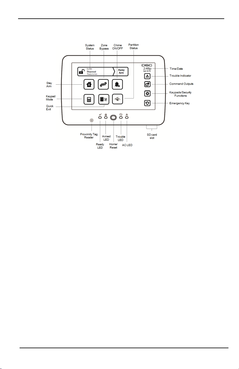
Figure 1- Controls and Indicators
The HS2TCHP E Touchscreen is an interactive touch-sensitive color LCD that can be used on any PowerSeries
Neo control panel. Due to the custom requirements of individual installations, some of the features described here
may perform differently than described. Refer to your Installer's Instructions for the details of your specific installation and to the User Manual for general security system information.
General System Operation
Your security system is made up of a DSC control panel, one or more keypads and various sensors and detectors.
The control panel will be mounted out of the way in a utilit y closet or in a basement. The metal cabinet contains
the system electronics, fuses and standby battery.
Note: Only the installer or service professional shall have access to the control panel.
All the keypads have an audible indicator and command entry keys. The keypad is used to send commands to the
system and to display the current system status. The keypad(s) wil l be mounted in a convenient location inside
the protected premises close to the entry/exit door(s).
The security system has several zones of protection, each connected to one or more sensors (motion detectors,
glassbreak detectors, door contacts, etc.). "Alarm Memory" on page 14 for information on sensors in alarm for this
Touchscreen keypad.
About Your Security System
Your DSC Security System has been designed to provide you with the greatest possible flexibility and convenience. Read this manual carefully and have your installer instruct you on your system's operation and on which
features have been implemented in your system. All users of this system should be equally instructed in i ts use.
Fill out the “System Information” page with all of your zone information and access codes and store this manual
in a safe pl ace for future reference.
Note: The PowerSeries security system includes specific false alarm reduction features and is classified in accordance with ANSI/SIA CP-01-2010 Control Panel Standard - Features for False Alarm Reduction. Please consult your
installer for further information regarding the false alarm reduction features built into your system as all are not
covered in this manual.
- 6 -

Introduction
Carbon Monoxide Detection (must be enabled by your Installer)
This equipment is capable of monitoring carbon monoxide detectors and providing a warning if carbon monoxide
is detected. Please read the Family Escape Planning guidelines in this manual and instructions that are available
with the carbon monoxide detector.
Fire Detection (must be enabled by your Installer)
This equipment is capable of monitoring fire detection devices such as smoke detectors and providing a warning
if a fire condition is detected. Good fire detection depends on having adequate number of detectors placed in
appropriate locations. This equipment should be installed in accordance with NFPA 72 (N.F.P.A., Batterymarch
Park, Quincey MA 02269). Carefully review the Family Escape Planning guidelines in this manual.
Testing
To ensure that your system cont inues to function as intended, you must test it weekly. Please refer to the “Testing
your System” section in this manual. If your system does not function properly, call your installing company for
service.
Monitoring
This system is capable of transmitting alarms, troubles and emergency information to a central st ation. If you initiate an alarm by mistake, immediately call the central station to prevent an unnecessary response.
Note: The monitoring function must be enabled by the installer before it becomes functional.
Note: There is a communicator delay of 30 seconds in this control panel. It can be removed, or it can be increased
up to 45 seconds, at the option of the end-user by consulting with the installer.
Note: For CP-01 systems, the monitoring function must be enabled by the install er before it becomes functional.
Maintenance
With normal use, the system requires minimum maintenance. Note the following points:
l Use the system test described in “Testing Your System” to check the battery condition. We recommend,
however that the standby batt eries be replaced every 3 - 5 years.
l For other system devices such as smoke detectors, passive infrared, ultrasonic or microwave motion
detectors, or glassbreak detectors, consult the manufacturer's literature for t esting and maintenance
instructions.
Important Notice
A security system cannot prevent emergencies. It is only intended to alert you and, if included, your central station of an emergency situation. Security systems are very reliable but they may not work under all conditions, and
they are not a substi tute for prudent security practices or life and property insurance. Your security system should
be installed and servi ced by qualified security professionals who should inst ruct you on the level of protection
that has been provided and on system operations.
- 7 -
Specifications and Features
Specifications and Features
Display 7" TFT (800 x 480) pixel) Color Touchscreen
Home button Home/Calibration/Reset
LED indicators 4 (Ready, Armed, Trouble, AC)
Dimensions (mounting) 8.5" x 5.1" x 0.8" [127.9 mm (L) x 195 mm (W) x 20.35 mm (D)]
Horizontal viewing angle 70°
Vertical viewing angle 70° (top), 50° (bottom)
Brightness 280 cd/m²
Operating environment
SD card slot Holds any standard Secure Digital (SD) card* (32 x 24 x 2.1 mm)
*If necessary, the SD card can be formatted to file system FAT16 or 32 using a PC. The maximum size SD card
supported is 32GB.
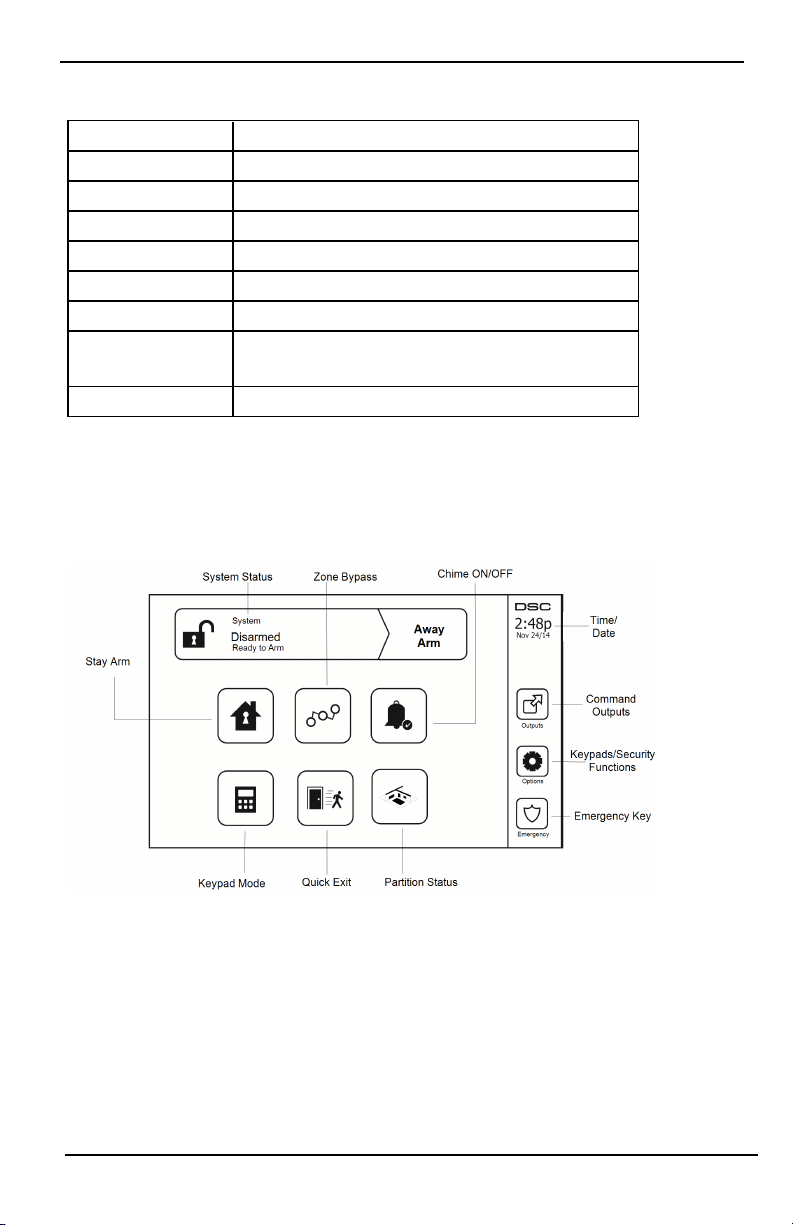
Welcome Screen
The date and time are displayed in the upper right corner of the screen. The system status (i.e., Ready, Armed, Exit
Delay etc.) is displayed at the top of the screen.
Figure 2- Welcome Screen
0°C to +49°C (32°F to 120°F)
93% (max) relative humidity non-condensing
- 8 -
Emergency Keys
Emergency Keys
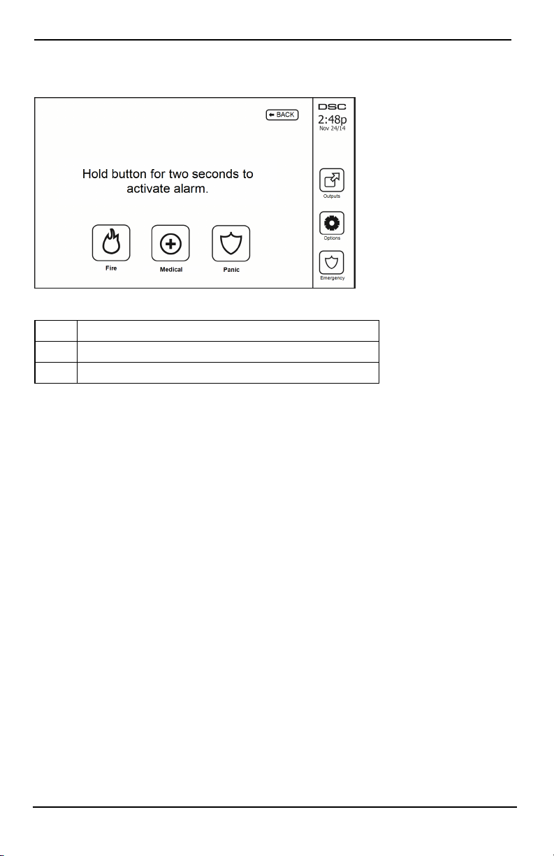
Figure 3- Emergency Screen
When the emergency key is pressed, a new screen is displayed with:
Fire Fire Assistance Required. Press and hold for 2 seconds to activate.
Medical Medical Assistance Required. Press and hold for 2 seconds to activate.
Panic Police Assistance Required. Press and hol d for 2 seconds to activate.
Important: The Medical and Panic keys are ON by default. The Fire key will not function unless programmed by
the Installer. Please ask your installer if the Fire, Medical and Panic keys are enabled.
Note: These events are recorded in the log.
- 9 -
Arming and Disarming the System
Arming and Disarming the System
Stay Arm (Arming the Perimeter)
Ask your alarm company if this function is available on your system.
Stay arming bypasses the interior protection (i.e., motion sensors) and arms the perimeter of the system (i.e., doors
and windows). Close all sensors (i.e., stop motion and close doors). The Ready ( ) indicator should be on. Press
the Stay Arm button and/or enter your Access Code and do not leave the premises (if your installer has pro-
grammed this button). During exit delay, the Armed ( ) and Ready( )indicators turn on to visually indicate
that the system is arming.
When the exit delay expires, the Ready LED turns off, the Armed LED remains on and the keypad stops sounding
to indicate that the alarm system is armed.
Note: For SIA FAR listed panels, the Stay Arming exit delay will be twice as long as the Away Arming exit
delay.
Silent Exit Delay
If the system is armed using the Stay Arm button or using the "No Entry" Arming method ([*][9][access code], the
audible progress annunciation (keypad buzzer) is silenced and the exit time doubled for that exit period only (CP01 versions only).
Note: For non CP-01 versions, Standard exit time is used.
When Stay Arm is selected from the Home screen:
l The display indicates “Exit Delay in Progress,” and the pre-programmed exit delay begins.
l The Armed LED Indicator turns on.
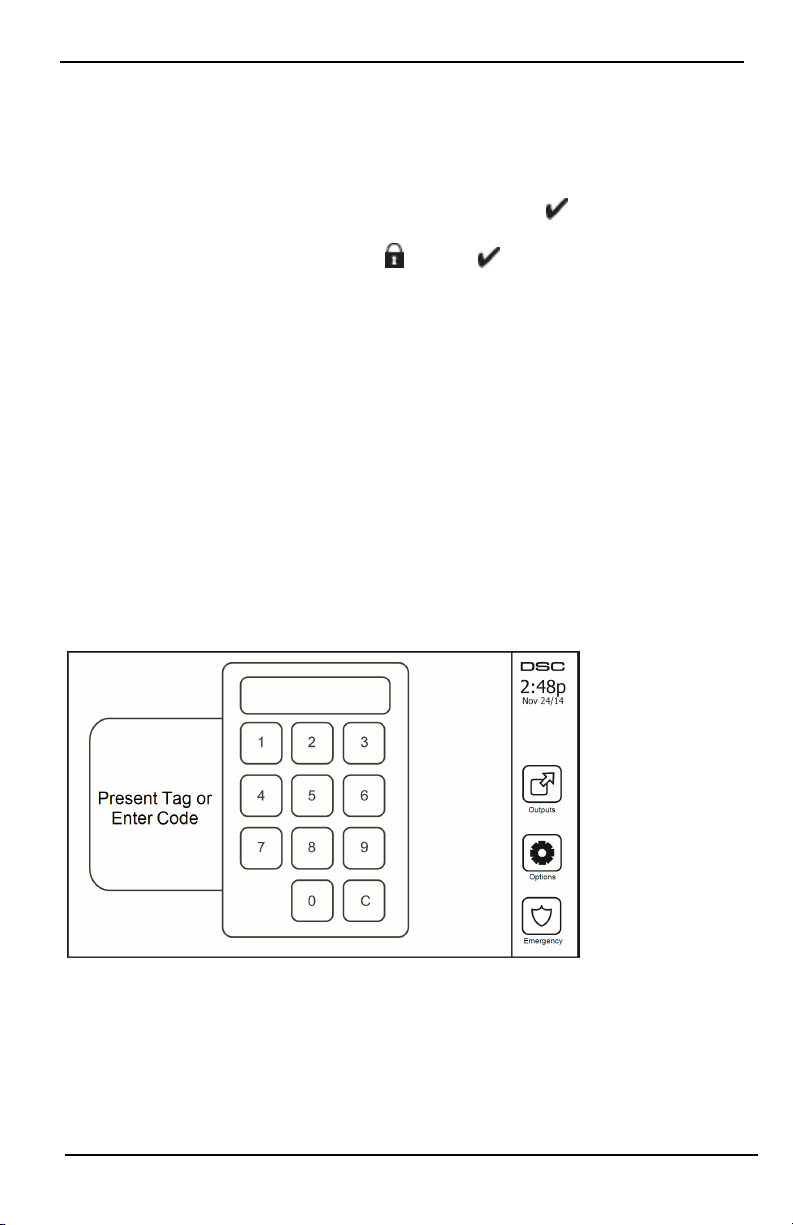
If Quick Arm is not enabled by the installer, then a numerical keypad is displayed (see following figure). Enter a
valid access code to proceed.
Figure 4- Keypad
If Disarm is selected during the exit delay, a numeric keypad is displayed.
l Enter (tap) your access code.
l The arming sequence is aborted and the system returns to the Home screen.
l The Armed LED turns OFF.
At the end of the pre-programmed exit delay:
- 10 -

Arming and Disarming the System
l The Disarm screen is displayed.
l The Ready Indicator turns OFF.
l “Stay Armed-Bypass” is displayed in the Status Bar.
Note: This screen will go into stand-by mode after 15 minutes. Tap the screen to restore the display.
Disarm
If Disarm is selected:
l A numerical keypad is displayed.
l Enter your Access Code in the keypad.
l The system returns t o the Home screen and the red Armed indicator turns OFF.
l The alarm status is momentarily displayed in the status bar, then "Ready" is displayed.
l The green Ready indicator turns ON.
Note: If your code is invalid, the system will not disarm and a 2-second error tone will sound. If this happens,
press # and try again.
Away Arm
When Away Arm is selected:
l Enter a valid access code to proceed.
l The Armed LED Indicator turns ON.
l "Exit Delay in Progress" is displayed i n the Status Bar. The pre-programmed exit delay begins.
l The touchscreen "beeps" at a 1-second urgency interval during the exit delay. Then 3 beeps sound in the
last 10 seconds.
Note: If Quick Arm is not enabled by the inst aller, a numerical keypad is displayed.
If Disarm is selected during the exit delay:
l A numeric keypad is displayed. Tap your access code.
l The Arming sequence is aborted and the system returns to the Home screen.
l The Armed LED turns OFF.
At the end of the pre-programmed exit delay:
l The Disarm screen is displayed.
l The Ready Indicator turns OFF.
l "Away Armed" i s displayed in the Status Bar.
Exit Delay Time Restart
The control panel provides an option where if an entry/exit zone is tripped, a second time prior to the end of the
exit delay, the exit delay time restarts. The exit delay ti mer can only be restarted once.
Alarm Cancel Window
The control panel provides a period of time in which the user can cancel the alarm transmission. The minimum duration of this time is five minutes. If the programmed alarm transmission delay has expired, canceling an alarm
sends a message to the monitoring station. Upon a successful transmission of the cancelation message, the keypad
will beep 6 times.
- 11 -

Arming and Disarming the System
Bell/Siren Sounds After Away Arming
Audible Exit Fault
In an attempt to reduce false alarms, the Audibl e Exit Fault is designed to notify you of an improper exit when
arming t he system in the Away mode. In the event that you fail to exit the premises during the allotted exit delay
period, or if you do not securely close the Exit/Entry door, the system will notify you that it was improperly
armed in two ways: the keypad will emit one continuous beep and the bell or siren will sound.
Your installer will tell you if this feature has been enabled on your system. If this occurs:
1. Re-enter the premises.
2. Enter your access code to disarm the system. You must do this before the entry delay timer expires.
3. Follow the Away arming procedure again, making sure t o close the entry/exit door properly.
Arming Error
An error tone will sound if the system is unable to arm. Thi s will happen if the system is not ready to arm (i.e.,
sensors are open), or if an incorrect user code has been entered. If this happens, ensure all sensors are secure. Press
[#] and try again, ensuring that a valid access code is entered. Please check with your installer to determine if arming is inhibited by any other means.
Remote Arming and Disarming
The system can be armed and/or disarmed using the remote wireless key or proximity tag. When arming the system by using the Arm button on the wireless key, the system will acknowledge the command by sounding a
single bell squawk (if bell squawk is enabled). When disarming using the Disarm button on the wireless key, the
system will acknowledge the command by sounding two bell squawks (if bell squawk is enabled) that can be
heard from the exterior of the premises.
To arm the syst em with a proximity tag:
l Present your proximity tag to a keypad equipped with a proximity sensor anytime the system Ready
indicator is on.
l If configured by your installer, enter your access code.
To disarm the system with a proximity tag:
l Present your proximity tag to a keypad equipped with a proximity sensor anytime the system is armed.
(Armed indicator is on) and if configured as required, enter your access code.
l If you walk through the entry door the keypad will beep. Present your Proximity tag within ____
seconds to avoid an alarm condition.
Using Your System
This section provides additional information about how to use your alarm system.
When Alarm Sounds
The system can generate 3 different alarm sounds:
l Temporal/pulsed siren = Fire Alarm
l 4 beeps, 5-second pause, 4 beeps = Carbon Monoxide Alarm
l Continuous siren = Intrusion (Burglary Alarm)
Note: The priority of signals is fire alarm, carbon monoxide alarm and medical alarm, then burglary alarm.
Note: Medical alarm is silent. It only results in an alarm transmission to the monitoring station.
Intrusion (Burglary) Alarm Continuous Siren
If you are unsure of the source of the alarm, approach with caution! If the alarm was accidental,
enter your Access Code to silence the alarm. Call your central station to avoid a dispatch.
- 12 -

Arming and Disarming the System
If the Intrusion Alarm was Accidental
1. Enter your Access Code to silence the alarm. If the code is entered within 30s (or the programmed value of
the alarm transmission delay) the transmission of the alarm to the monitoring station will be canceled.
2. Call your central station to avoid a dispatch.
Fire Alarm Pulsed Siren
Follow your emergency evacuation plan immediately!
If the fire alarm was accidental (e.g., burned toast, bathroom steam, etc.), enter your Access Code to sil ence the
alarm. Call your central station to avoid a dispatch. Ask your alarm company if your system has been equipped
with fire detection. To reset the detectors, see the Sensor Reset section.
Wireless Carbon Monoxide Alarm
Activation of your CO alarm indicates the presence of carbon monoxide (CO), which can be fatal. During an alarm,
the red LED on the CO detector flashes rapidly and the buzzer sounds with a repeating cadence of: 4 quick beeps,
5-second pause, 4 quick beeps. Also, during an alarm, the siren connected to the control panel produces a repeating cadence of 4 quick beeps, 5-second pause, 4 quick beeps. The keypad will also provide audible and visual
indication of the CO alarm.
If an Alarm Sounds:
1. Operate silence button.
2. Call emergency services or your fire department.
3. Immediately move outdoors or to an open door/window.
Warning: Carefully review your Carbon Monoxide Installation/User Guide to determine the necessary actions
required to ensure your safety and ensure that the equipment is operating correctly. Incorporate the steps outlined
in the guide into your evacuation plan.
- 13 -
Troubles
Troubles
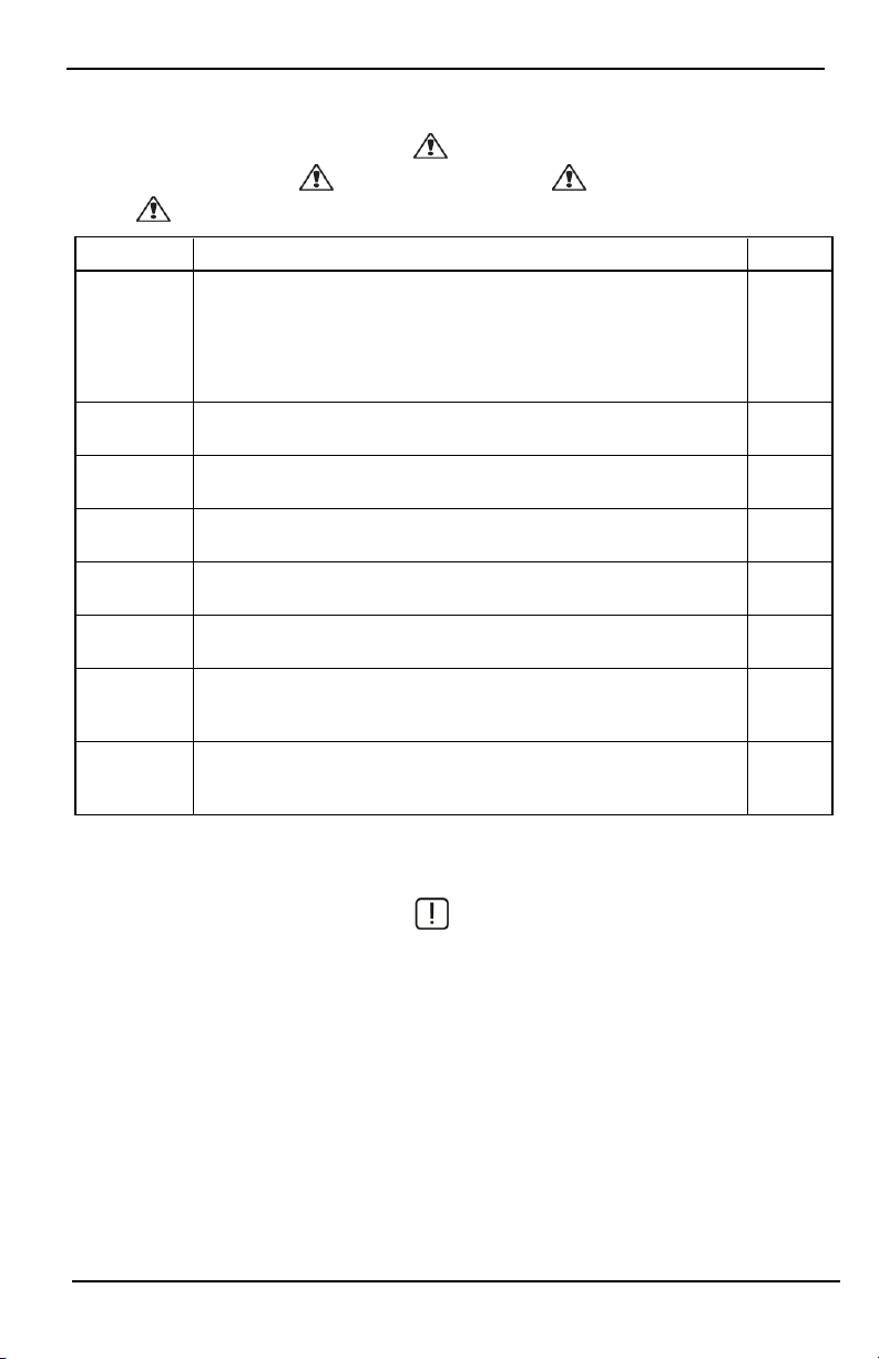
When a trouble condition is detected, the Trouble ( ) or System indicator will turn on, and the keypad will
beep every 10 seconds. Press the ( ) key to silence the beeps. Press ( ) to view the trouble condition. The
Trouble ( ) or System indicator will flash. The corresponding trouble will light up.
Troubles Comments Action
Service
Required (Press
for more
details)
AC Loss
Phone Trouble The system has detected that the telephone line i s disconnected.
Communication
Failure
Zone Fault
Zone Tamper
Wireless Low
Battery
Loss of Clock
Low Battery General System Supervision
Bell Circuit RF Jam Detected
General System Trouble Panel Low Battery
General System Tamper Panel AC Loss
If the building and/or neighborhood has lost electrical power, the system will
continue to operate on battery for several hours.
The system attempted to communicate with the monitoring st ation, but failed.
This may be due to Telephone Line Fault.
The system is experiencing difficulties with one or more sensors on the system.
Press to display the zone.
The system has detected a tamper condition with one or more sensors on the system. Press to display the zone.
The system has detected a low battery condition with one or more modules/sensors on the system. Press to display the zone, keypad, wireless key(s) and
RF Delinquency low battery conditions. Press again to see zone troubles.
If complete power was lost (AC and Battery), the time and date will need to be
reprogrammed.
Call for
service
Call for
service
Call for
service
Call for
service
Call for
service
Call for
service
Call for
service
Reprogram
Time &
Date
Alarm Memory
When an alarm occurs, the Alarm indicator flashes.
To view which sensor(s) generated the alarm, press Alarms.
The sensor number where the alarm occurred will be displayed (e.g., zone 3). Use the [<][>] scroll keys to view the
sensors in alarm memory. Press Back or Home to exit. To clear the memory, arm and disarm the system. If an alarm
sounded while armed, the keypad will automatically go to alarm memory when you disarm the system. In this
instance, you should approach with caution, as the intruder may still be within the building/premises.
- 14 -
Troubles
Figure 5- Alarms in Memory
Sensor Reset
Certain sensors, after having detected an alarm condition, require a reset to exit the alarm condition (e.g., glass
break sensors, smoke detectors, etc.). Ask your alarm company if this function is required on your system.
To reset the detectors, press the Reset (Command Output 2 if the installer did not program a label) button on the
Outputs screen. If a sensor fails to reset, it may still be detecting an alarm condition. If the sensor reset is successful, the alarm is canceled. If unsuccessful, the alarm will reactivate or continue.
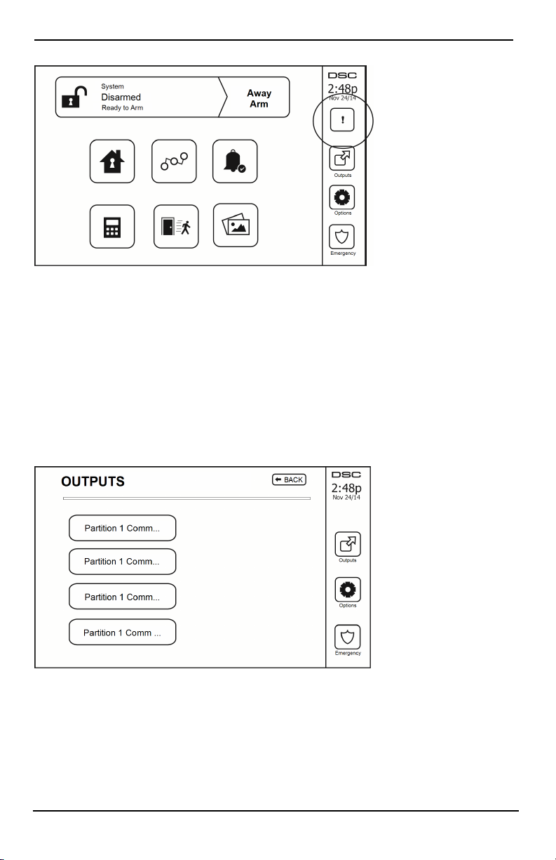
Outputs
Your installer may have programmed these keys to perform various functions (reset smoke detector after an alarm,
open your garage door, etc.) To activate these functions, press Output and then press the appropriate option. For
additional information, refer to the section: Sensor reset.
Figure 6- Outputs
- 15 -

Additional Functions
Additional Functions
Photos
You can create a slideshow of photos to View on the keypad. Photos are added usi ng an SD card (32x24x2.1 mm.
Not supplied).
The photos must be .jpg format and can be up to 1280 x 720 in size. For best results, use 800 x 480 resolut ion.
Use phot o editing software to adjust the size of your photos.
To start the slideshow, set the screen saver to photo mode. The slideshow plays automaticall y until the timeout is
reached or the screen is touched again.
To add photos:
1. Press Options, User Functions, Keypad Config, Picture Frame, Select Photos. Thumbnail images of the photos
on your SD card are displayed.
2. Touch an image to add it to the slideshow. Touch it a second t ime to remove it.
Use the Transition Time slider to program the amount of time each photo is on screen, from 5 seconds to 1
minute.
Use the Photo Frame Timeout slider to control how long your slideshow plays for, from 1 minute to 2 hours.
Select Never to keep the slideshow running until the screen is touched.
Note: Maximum of 255 photos are supported.
Quick Exit
If the system is armed and you need to exit, use the quick exit function to avoid di sarming and rearming the system. To activate this function, tap the Quick Exit icon. You have 2 minutes to leave the premises through your
exit door. When the door is closed again the remaining exit time is canceled.
Time & Date Programming
Tap on Options. Select User Functions [Master Code] and then select Time & Date. Tap on the section you would
like to change and use the up/down arrows to change time/date. Once done, press Save.
Keypad Mode
This option allows the HS2TCHP E Touchscreen to function as a traditional DSC keypad.
Door Chime (Chime enable/disable)
The keypad indicates the current state of the door chime function (Enabled or Disabled). To choose the opposite
function, tap the 'Chime' icon. Three beeps indicate that the chime is ON (Enabl ed). One long beep i ndicates that
chime is OFF (Disabled).
Note: The door chime feature should be used in Disarmed mode only.
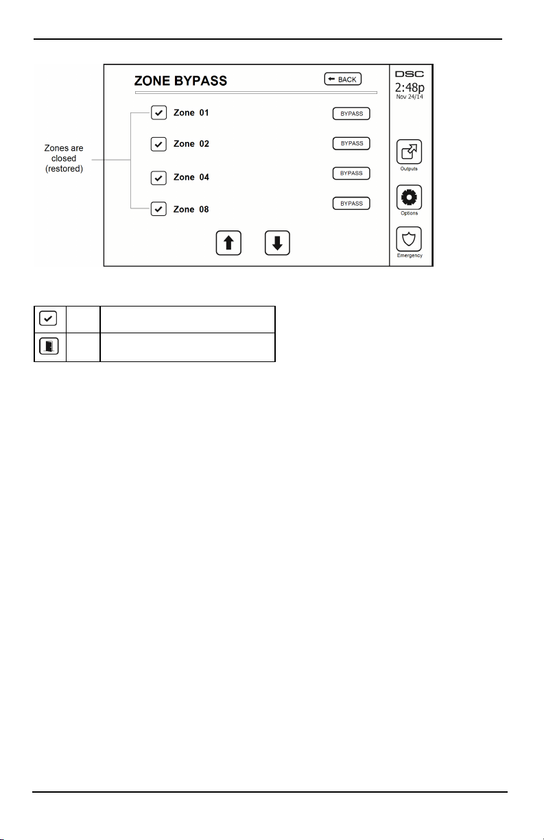
Zone Bypass
This screen allows you to view the status of the zones on the system.
- 16 -
Options Menu
Figure 7- Zone Closed
Zone Status Indicators
Ready Zone is closed
Open The zone is open and needs to be closed
Bypassed Zones
Use the zone bypass feature when a zone is open but the system needs to be armed. Bypassed zones will not cause
an alarm when opened. Bypassing zones reduces the level of security. If you are bypassing a zone because it i s not
functioning, call a service technician immediately so that the problem can be resolved and your system returned to
proper working order.
Ensure that no zones are unintentionally bypassed when arming your system. Zone bypassing can only be performed while the system is disarmed. Bypassed zones are automatically canceled each time the system is disarmed
and must be bypassed again, if required, before the next arming.
Note: 24-hour zones can only be unbypassed manually.
Note: For security reasons, your installer has programmed the system to prevent certain zones from being
bypassed. (e.g., smoke detectors).
Bypassing Zones with a HS2TCHP
When in the Zone Status page, scroll up/down through the desired zones, and tap on the bypass icon to bypass
the zone. To unbypass a zone, tap the unbypass icon.
Note: For UL listed installations, zones can only be bypassed manually.
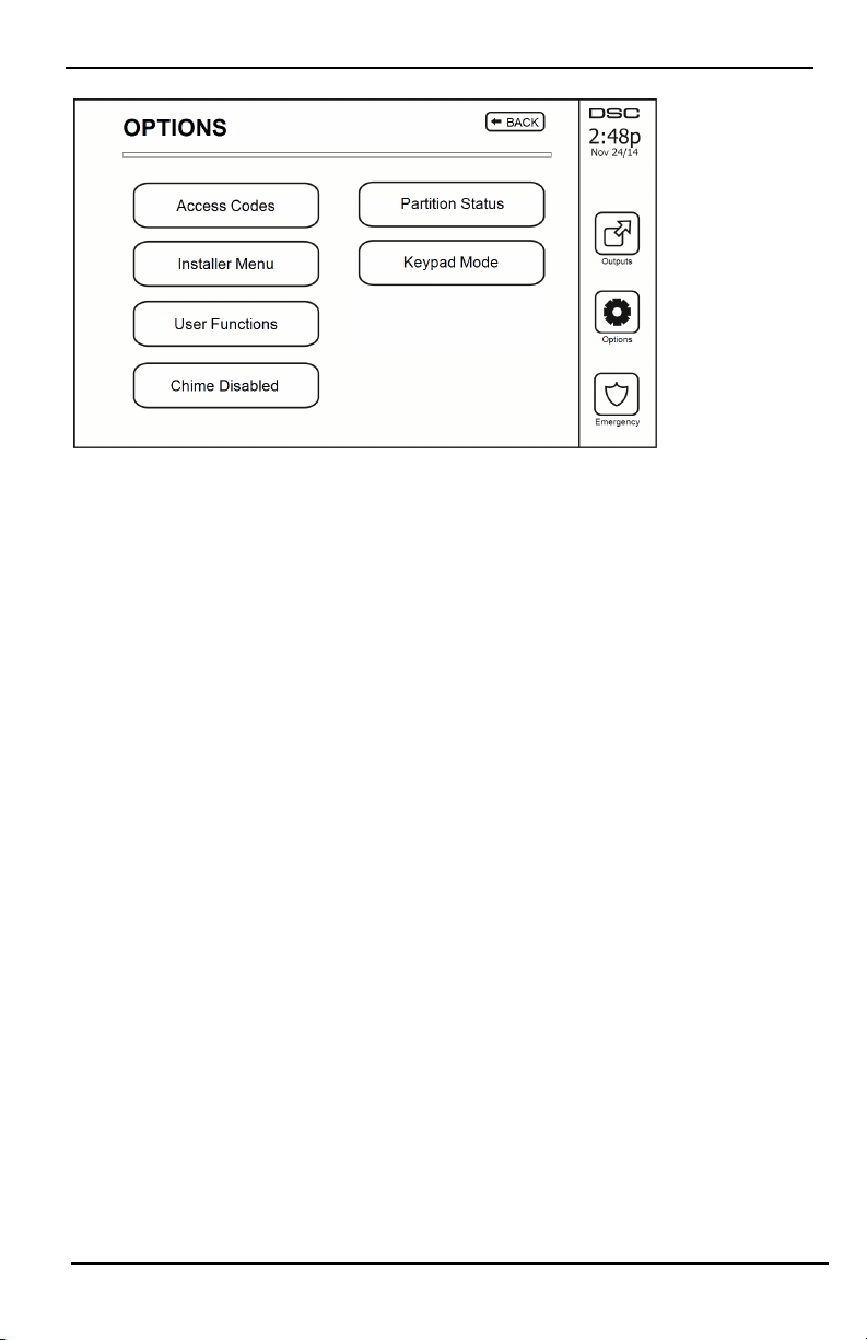
Options Menu
Access t he following functions by pressing Options on the right side of the home page. See the online HS2TCHP
E User Manual for more information.
l Access Codes
l Installer Menu
l User Functions
l Chime Enabled/Disabled
l Partition Status
l Keypad Mode
- 17 -
Options Menu
Figure 8- Options
Access Codes
When Access Codes is selected from the Options menu, the keypad prompts for a Master Code. When a valid
Master Code is entered, a numeric keypad is displayed with arrows to scroll through the list of users. Press the
Select button to enter the user options.
Set Access Code: adds/edits the 4-digit or 6-digit code
Set Partitions: assigns the user to partitions
User Options: enables/disables different options for the user
Delete User: deletes the user from the system
The access codes have programmable attributes which allow zone bypassing, or one-time use activation.
Master Code (Access Code 01): The master code, if programmed, can only be changed by the installer.
Supervisor Codes: These codes can be used to program additional codes which have equal or lesser attributes.
Once programmed, the supervisor codes receive the master code’s attributes. These attributes are changeable. Any
user code can be made a supervisor code by enabling User Code Attribute 1 (see the following for details).
Duress Codes: Duress codes are st andard user codes that transmit the Duress Reporting Code when entered to
perform any function on the system. Any user code can be made a duress code by enabling User Code Attribute 2
(see the following for details).
Note: Duress codes are not valid when entering User Programming, Master Functions or Installer’s sections.
Note: Access codes cannot be programmed as a duplicate or as a “Code +/- 1”.
Assign Proximity Tags
Depending on how your keypad is programmed, proximity tags can be used to either arm/disarm the system or to
perform a programmed function (e.g. unlock a cabinet or storeroom door). Present the tag to the tag reader.
1. Press [*][5]Master/Supervisor Code].
2. Enter a 4-digit or 6-digit user code.
3. Press 2.
4. Pass the enrolled tag near the tag reader.
Delete Proximity Tags
To delete a proximit y tag:
1. Select Options, Access Codes [ent er Master code].
2. Select a user to delete.
- 18 -

Options Menu
3. Select Prox Tag Prog then delete.
User Code Attributes
1. The default attributes of a new code wil l be the attributes of the code used to enter User Programming
whether it is a new code or an existing code being programmed.
2. System Master Code 01 has partition access for all partitions, as well as attributes 3-4 ON by default.
Note: These attributes are not changeable.
Inherent Attributes (all codes except installer and maintenance)
Arm/Disarm: Any access code with partition access enabled will be valid for arming and disarming that par-
tition.
Command Outputs ([*][7][1], [*][7][2], [*][7][3], and [*][7][4]): If these outputs require access code
entry, any Access Code with partition access will be valid for performing the command output functions on that
partition.
Programmable Attributes
1. Supervisor Code 5. For Future Use
2. Duress Code 6. For Future Use
3. Zone Bypassing Enabled 7. Bell Squawk upon Arming/Disarming
4. Remote Access 8. One Time Use Code
Bell Squawk Attribute
This attribute is used to determine whether an access code should generate an arming/disarming Bell Squawk upon
entry of the code for Away arming. The wireless keys with access codes associated with them may generate Arming/Disarming Bell squawks. If desired, this option may be used with codes that are manually entered. Please contact your installer to have this programmed.
Note: The Master Code cannot use the Bell Squawk attribute, but i s required to enable it for other codes.
Note: This feature cannot prevent the Arming/Disarming squawks from being generated if an access code assigned
to a wireless key is manually entered at a keypad.
Note: This feature is used to annunciate fire trouble signals and also trouble conditions for medical applications.
Partition Assignment
1. This section is used to assign users to availabl e partitions. To assign partitions:
2. Select Options > Access Codes.
3. Enter the master code.
4. Select a user.
5. Select Partition Attributes.
6. Select the partition(s) to assign to the user.
Notes on Access Codes and Programming
l The master code’s attributes cannot be changed.
l When a new code is programmed in User Programming it will be checked against all other codes i n the
system. If a dupli cate code is found, an error tone is given and the code is returned to what it was before
it was changed. This applies to both 4 and 6-digit codes.
Erasing an Access Code
To erase a code, select the code and choose Delete User. The system will delete the code immediately and the user
will be returned to select another code.
Installer Menu
These functions are for the installer’s use only.
- 19 -

Options Menu
User Functions
First disarm the system then enter Options, User Functions, then Master Code. This command is used to gain
access to the following list of master functions of the system:
Time and Date
Enter desired time and date.
Auto-Arm Time
The system can be programmed to arm at a programmed time each day, per partiti on. Upon entry of this section,
enter the desired Auto-Arm time for each day of the week.
At the selected Auto-Arm time, the keypad buzzers will sound for a programmed amount of time (programmable
by the installer only) to warn that an auto-arm is in progress. The bell can also be programmed to squawk once
every 10 seconds during this warning period. When the warning period is complete, the system will arm with no
exit delay and in Away mode.
Auto-Arming can be canceled or postponed by entering a valid access code only during the programmed warning
period. Auto-Arming will be attempted at the same time the next day. When the Auto-Arming process is canceled
or postponed, the Auto-arm Cancelation Reporting Code will be transmitted (if programmed).
If arming is inhibited by one of the foll owing, the Auto-Arm Cancelation transmission will be communicated:
l AC / DC Inhibit Arm
l Latching Syst em Tampers
l Zone Expander Supervisory Fault
Note: For UL/ULC listed installations, the auto-arm feature shall be canceled when there are zones in an off-normal condition.
Enable DLS/Allow System Service
If enabled, the installer wi ll be able to access Installer Programming via remote (DLS). The DLS window will
remain open for 6 hrs, during which time the installer will be able t o enter DLS an unlimit ed number of times.
After the 6-hr window has expired, Installer’s Programming will be unavailable again until the window is reopened.
Event Buffer
l Displays the date, time and the full description of the event
l The Log is organized from the most recent event (Top) to past events (Down)
l The Left arrow scrolls forward in time
l The Right arrow scrolls back in time
l The Back returns you to the Home screen
l This screen will time out to the Home screen after 30 seconds of inactivity
System Test
The system’s bell output, keypad lights and communicator are tested. This test will also measure the panel’s
standby battery.
Important:
l To ensure that your system cont inues to function as intended, you must test your system weekly.
l For UL HOME HEALTH CARE listed applications, the system shall also be tested weekly without AC
power. To remove AC from the control unit, remove the screw from the restraining tab of the plug in
adapter and remove the adapter from the AC outlet. After completing the test of the unit using only the
battery backup source, reconnect the plug in adapter and attach the screw through the restraining tab, so
that the adapter is securely attached to the outlet.
l Should your system fail to function properly, contact your installation company immediately.
- 20 -
Options Menu
l All smoke detectors must be tested by your smoke detector installer once a year to ensure proper oper-
ation.
Auto-Arm/Disarm Control
Pressing Auto-Arm while in the User Function menu will enable (three beeps) or disable (one long beep) the
Auto-Arm and Auto-Disarm feature, by partition. With this feature enabled, the panel wil l automatically arm in
Away mode (Stay/Away zones active) or disarm at the same time each day. The Auto-Arm time is programmed
with the Auto-Arm time button. Auto-Disarm must be programmed by the system installer.
User Call-up
This option gives your service provider temporary access to the alarm control panel for remote servicing.
Engineer's Reset
If an alarm has occurred on your system, the system will not allow you to rearm (Ready light is OFF). You will
need to contact your installer. They will check and reset the system for you. This may involve a visit to check
your system. After the reset is performed, your system will function properly again.
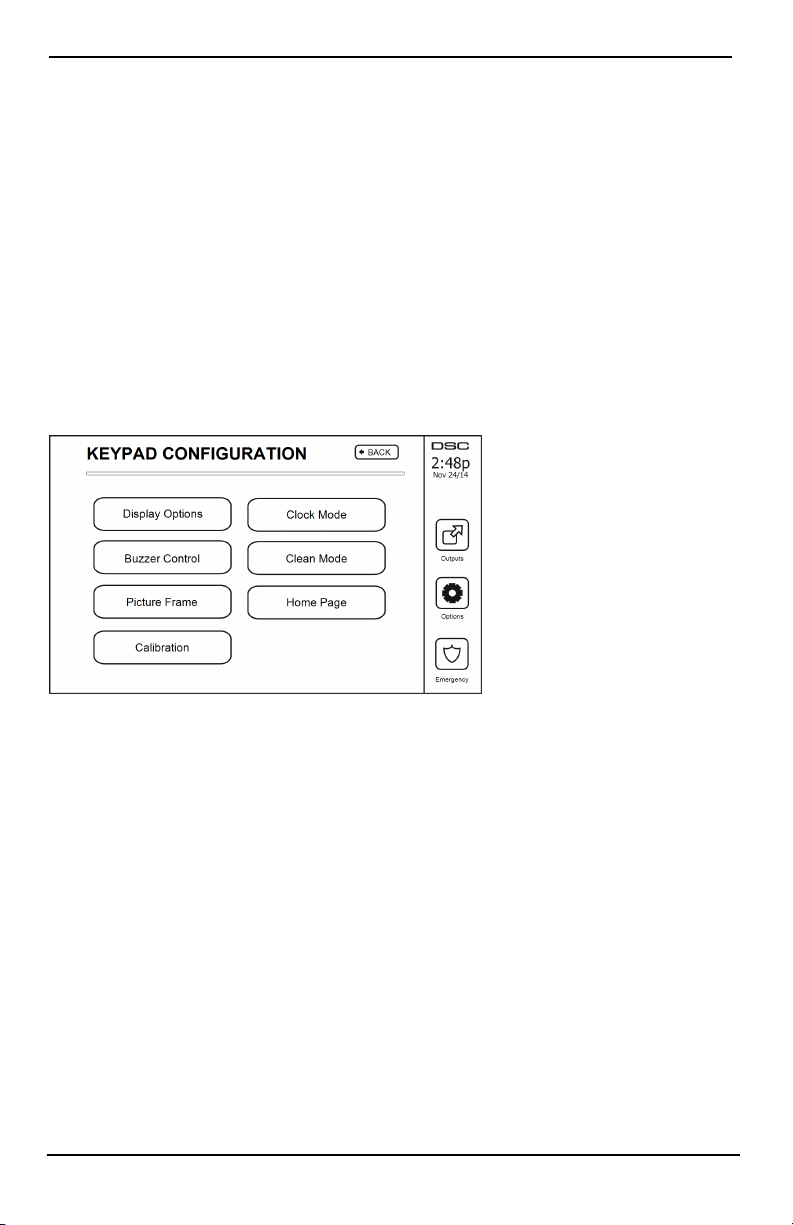
Keypad Configuration
Figure 9- Keypad Configuration
Display Options: sets the brightness and screen timeout of the Touchscreen, as well as screen saver options.
Buzzer Control: sets the buzzer volume of the Touchscreen. Note: For SIA CP-01, the buzzer volume shall not
be placed at the minimum setting.
Note: For UL/ULC installations, the buzzer level shall not be changed from the default level.
Picture Frame: selects the pictures that will be displayed on the sl ideshow.
Calibration: calibrates the Touchscreen.
Clock Mode: displays the digital clock.
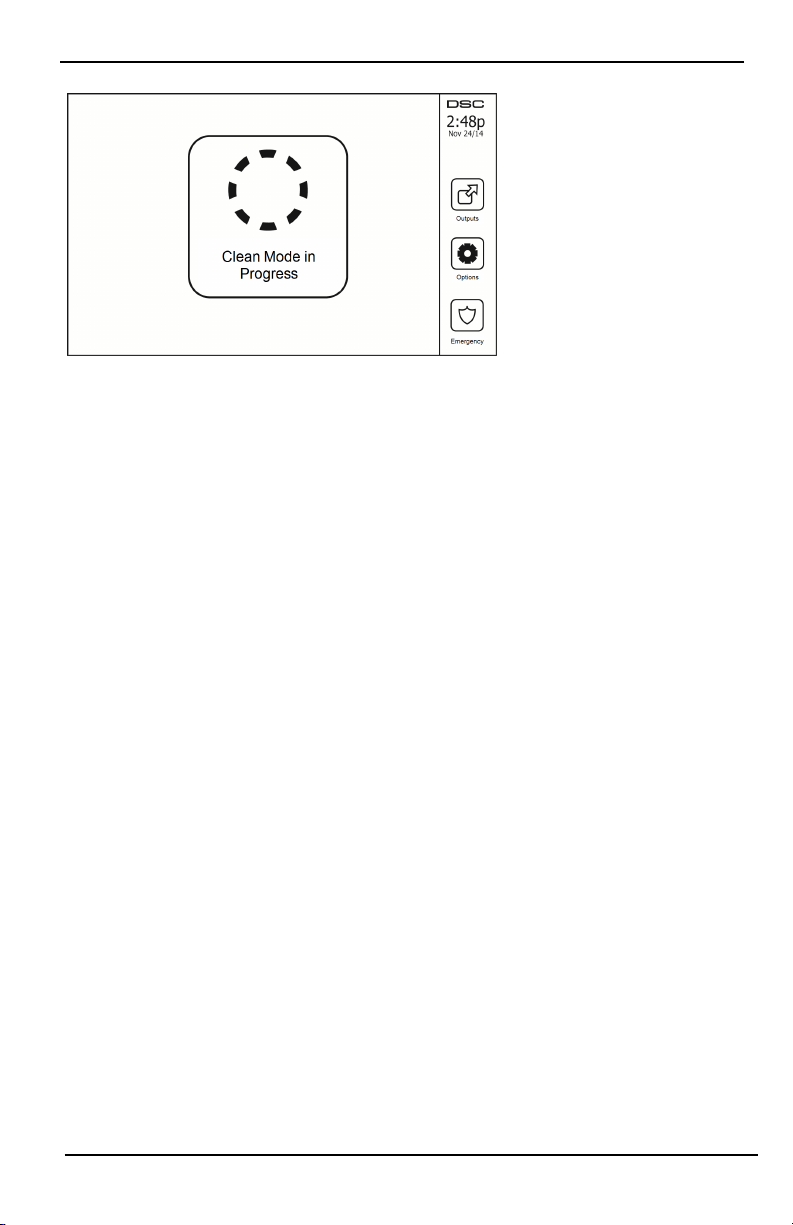
Clean Mode: allows the user to touch (i.e., clean) the screen without enabling or disabling any functions. The
screen will remain i n this mode for 30 seconds, then return to the Keypad Configuration screen.
- 21 -
Options Menu
Figure 10- Clean Mode
Home Page: can be configured i n one of two different views, Classic (square buttons) and Contemporary
(rondel).
Chime Enabled/Disabled
Door Chime: To turn the door chime function On/Off, tap the Chime icon. 3 beeps indicate that the chime is
ON. 1 long beep indicates the Chime is OFF.
Arming
Stay Arm: arms the system in Stay mode
Away Arm: arms t he system in Away mode
Night Arm: To fully arm the system when it has been armed in Stay Mode, press Night Arm button. All interior
zones will now be armed except for devices programmed as Night Zones. Night zones are only armed in Away
mode. Thi s permits limited movement within the premises when the system is ful ly armed. Ensure that your
installer has provided you with a list identifying zones programmed as night 18 zones. When the interior zones
have been activated (i.e., Night Arm), you must enter your access code to disarm the system to gain access to
interior areas that have not been programmed as night zones.
Quick Exit: refer to the section: Quick Exit
Global Away Arm: arms all partitions to which the User Code is assi gned, in Away mode.
Global Stay Arm: arms all partitions to which the User Code is assigned, in Stay mode.
No Entry Arm: arms the system with no entry.
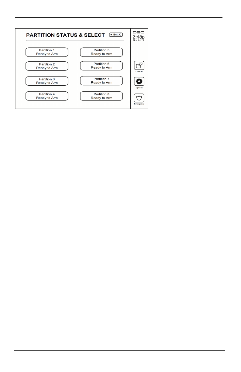
Partition Status
To view the partition status, press Options, User Functions, then Partition Status. The keypad shows basic status
for up to 8 partitions, depending on the configuration of your system. Each partition is identified along with its
current status.
- 22 -
Managing Partitions
Figure 11- Partition Status
Keypad Mode
This option allows the HS2TCHP E Touchscreen to function as a traditional DSC keypad.
Managing Partitions
A partition is a limited area of the premises which operates independently from the other areas. Partitioning a system can be beneficial if the property has outbuildings that need to be secured independently of a main area or if
the home has a separate apartment. Each partition can have its own keypad, or a keypad can have access to all partitions. User access to partitions is controlled via access code. A master code can access the entire system and partitions, while a user code is limited to assigned partitions.
Partitions
Keypads can be configured to control an individual partition or all partitions.
Note: Access to this feature must be configured by your installer.
Single Partition Operation
Single partition keypads provide access to alarm functionality for an assigned partition.
Single partition keypads behave as follows:
l Displays the armed set state of the partition.
l Displays open zones, if assigned to the partition the keypad is on.
l Displays bypassed zones and allows zone bypassing or creating bypass groups of zones assigned to the
keypad partiti on.
l Displays system troubles (system low battery, system component faults/tampers).
l Displays alarms in memory that occurred on the partition.
l Allows the door chime to be Enabled/disabled.
l System test (sounds bells/PGMs assigned to the partition).
l Label programming (zone, partition and user labels for the partition).
l Command output controls (outputs assigned to the partition, or global outputs such as smoke detector
reset).
l Temperatures.
Loaning a Keypad to Another Partition
The HS2TCHP Touchscreen Keypad can be loaned to operate on other partitions. When a keypad is loaned to
another partition, it will behave on the loaned partition as if it was originally assigned there. An access code must
be entered before loaning a keypad to anot her partition. An access code is also required to perform any function
on that partition.
To loan a keypad to another partition:
- 23 -
Managing Partitions
1. Select Options > Partition Status.
2. Enter your access code.
3. Select the partition to loan the keypad to. If t he keypad is inactive for more than 30 seconds, it will
return to its original partition.
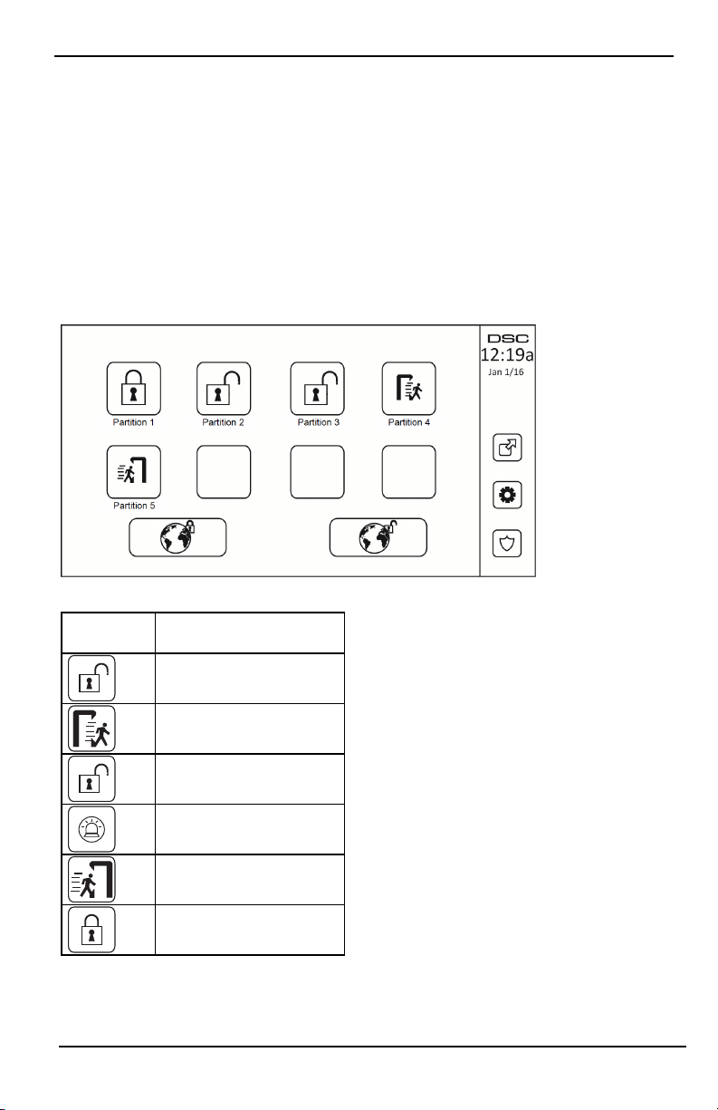
Global Keypad Operation
Once a valid access code is entered, a global keypad will di splay the status of any partitions that the user has permission to view. From this overview, you can loan the global keypad t o a partition, arm all partitions or disarm
all partitions. The status of each partition will be identified by a partition status icon. For an explanation of partition status icons, see the table below. The global arm and global di sarm buttons will arm or disarm all displayed
partitions.
To Loan a Global Keypad t o Another Partition:
1. Select Partition Status.
2. Select the partition to loan the keypad to.
Figure 12- Global Keypad Mode
Partition
Status Icon
Description
GREEN BACKGROUND
Partition is ready to be armed
Partition is in exi t delay
GRAY BACKGROUND
Partition is not ready to be armed
Partition is in alarm
Partition is in ent ry delay
Partition is armed
- 24 -

Managing Partitions
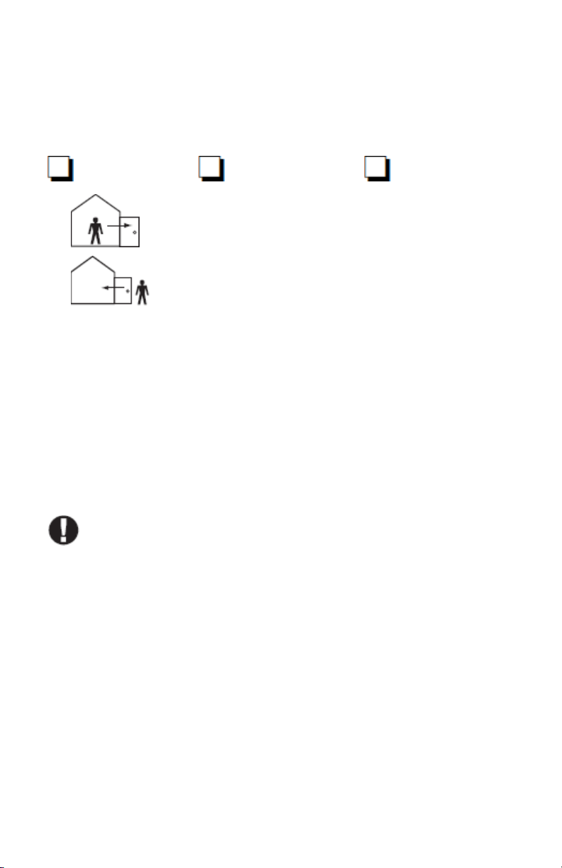
Fire and CO Zone Types
l If a Fire zone generates an alarm only the partition the fire zone is assigned to will go into alarm. Other
partitions retain their current state.
l If the [F] key on a global keypad is used to generate an alarm all enabled partitions will go into alarm.
l One or more fire keypads may be located on any partition.
l On alarm, the fire auto-scroll display appears on all parti tion keypads and on all global keypads. Fire
alarm silence and fire system reset may be done directly on any partition keypad. To silence a fire or CO
alarm from a global keypad requires that t he global keypad be loaned to one of the partitions.
- 25 -

SMS Command and Control
SMS Command and Control
SMS Command and Control allows you to send text messages to your system, enabling t he system to perform certain actions. For a list of commands and how to send them see the SMS Commands table. As a security measure,
only authorized phone numbers can interact with your system. Messages from all other phone numbers will be
rejected.
Note: This is a supplementary feature t hat has not been investigated by UL/ULC. Must be enabl ed and configured
by your installer.
Looking up the Number to Call for SMS Commands
The phone number of t he system is set at the time of installation. To quickly find the phone number perform the
following steps.
1. Select User Functions > SMS Programming
2. Using the downward pointing arrow, scroll to Phone #9
3. The number programmed in Phone #9 is the phone number of the system. Send SMS commands to this
number to interact with your system.
Authorizing User Phones to Send SMS Commands
You can authorize up to eight phone numbers to interact with your system with SMS. Before the system will
accept an incoming SMS command, you must enter the sending phone number.
To authorize a phone for SMS Commands:
1. Select User Functions > SMS Programming
2. Using the up and down pointing arrows, scroll to an empty phone number and select it
3. Using the numerical pad, enter the phone number of the phone you want to authorize and press Save.
Sending SMS Commands to your System
In order to successfully send commands to your system from your cellphone, you must send SMS messages in the
proper format. If configured, commands require the inclusion of a User Access Code in your message. The access
code will be verified by the system before executing any commands.
Additional information about sending SMS commands:
l Text messages are not case sensitive and extra spaces are ignored.
l In multi-partition systems and if the User has rights to manage the desired partitions, commands can be
sent to specific partitions by including the partition number. For more information on partitions see:
"Managing Partitions".
l If the panel is configured to require an Access Code and the code is not sent or is invalid, the panel will
send a notification to the user advising the command was unsuccessful.
The following table lists all available SMS commands with examples of how to enter the Partition number and
access codes. The format for entering commands is as follows:
Note: Verify with your installer that the Partition number and access code are required in your SMS message. If
one or both are not required, do not enter them in your SMS message.
Note: Responses to Status and Alarm Memory requests may require more than 1 SMS message, depending on
status of the system. There is a 10 second delay between transmission of SMS messages.
- 26 -

SMS Commands
Commands Notes
Stay ArmSet Stay armssets the system
Away ArmSet Away armssets the system
Night ArmSet Night armssets the system
DisarmUnset DisarmsUnsets the system
Activate Command Output 1 Activates Output 1
Activate Command Output 2 Activates Output 2
Activate Command Output 3 Activates Output 3
Activate Command Output 4 Activates Output 4
Deactivate Command Output 1 Deactivates Output 1
Deactivate Command Output 2 Deactivates Output 2
Deactivate Command Output 3 Deactivates Output 3
Deactivate Command Output 4 Deactivates Output 4
Bypass 001 Bypasses specified zone number
Unbypass 001 Clears the bypass from the specified zone number
Omitting the partition number causes the system to
Status Request
Alarm Memory Request
Help
send a status report for all partitions. To request a
status report for a specific partition enter the appropriate partition number.
Omitting the partition number causes the system to
send a status report for all partitions. To request a
status report for a specific partition enter the appropriate partition number.
The Help command generates an SMS response listing all Interactive commands that can be sent t o
the module. Access Code is not required.

Testing Your System
Note: If you are going to perform a System Test, call your Monitoring Station to inform them when you begin and
also when you end the test.
Testing Your Keypad Sounder and Siren
The System Test performs a two-second check of the keypad sounder and bell or siren, in addition to testing the
keypad status lights and the panel backup battery.
1. Press Options, User Functions [Master Code], then System Test. The following will occur:
- The system activates all keypad sounders and bells or sirens for 2 seconds. All keypad lights turn ON.
- The Ready, Armed, and Trouble LEDs will flash for the duration of the test.
2. To exit the function menu, press [#].
Testing Your Entire System
All smoke detectors in this installation must be tested by your smoke detector installer or dealer once a year to
ensure they are functioning correctly. It is the user’s responsibility to test the system weekly (excluding smoke
detectors). Ensure you follow all the steps in the “Testing Your Keypad Sounder and Siren” section.
Note: Should the system fail to function properly, call your installation company for service immediately.
1. Prior to testing, ensure that the system is disarmed and the Ready light is on.
2. Close all zones t o return the system to the Ready state.
3. Perform a System Test by following the steps in the “Testi ng Your Keypad Sounder and Siren” section.
4. To test the zones, activate each detector in turn (e.g., open each door/window or walk in motion detector
areas).
On an HS2TCHP E keypad, the following message will be displayed when each zone (detector) is activated:
“Ready to Force,” “Not Ready”. Use the zone status button to view which zones are open. The message will disappear when the zones are closed.
Note: Some features described above will not be functional unless enabled by your installer. Ask your installer
which features are functional on your system.
Walk Test Mode
The installer can initiate a Walk Test mode for the system. While in Walk Test mode, the Ready, Armed, and
Trouble LEDs will flash to indicate that Walk Test is active. When the system automatically terminates the Walk
Test mode, it will annunciate with an audible warning (5 beeps every 10 seconds), beginning five minutes prior to
the termination of the test.
Allowing Computer Access To Your System
From time to time, your installer may need to send information to or retrieve information from your security system. Your installer will do this by having a computer call your system over the telephone line. You may need to
prepare your system to receive this ‘downloading’ call. To do this, press Options, User Functions [Master Code],
then System Serv/DLS from the Touchscreen. This allows downloading for a limited period of time. During this
time, the system will answer incoming downloading calls. For more information on this feature, please ask your
installer.
Reference Sheets
Fill out the following information for future reference and store this guide in a safe place.
System Information Enabled?
[F] FIRE [+] Medical [P] PANIC
The Exit Delay Time is ___ seconds
The Entry Delay Time is ___ seconds
For Service
Central Station Information:
Account #: ________________ Telephone #: ________________
Installer Information:
Company #: ________________ Telephone #: ________________
Battery Installation / Service Date:
__________________________
__________________________
__________________________
If you suspect a false alarm si gnal has been sent to the central monitoring station, call the station to
avoid an unnecessary response.

Access Codes (copy as needed)
HS2016/HS2032/HS2064/HS2128 MASTER CODE [01]: ________________________
Code Access Code Code Access Code Code
01 35 69
02 36 70
03 37 71
04 38 72
05 39 73
06 40 74
07 41 75
08 42 76
09 43 77
10 44 78
11 45 79
12 46 80
13 47 81
14 48 82
15 49 83
16 50 84
17 51 85
18 52 86
19 53 87
20 54 88
21 55 89
22 56 90
23 57 91
24 58 92
25 59 93
26 60 94
27 61 95
28 62 96
29 63 97
30 64 98
31 65 99
32 66 100
33 67
34 68
 Loading...