

Page 1
Models BB, SD, HIP, and AP
Specific Application Sprinklers
For Protecting Attics
Worldwide
Contacts
www.tyco-fire.com
General
Description
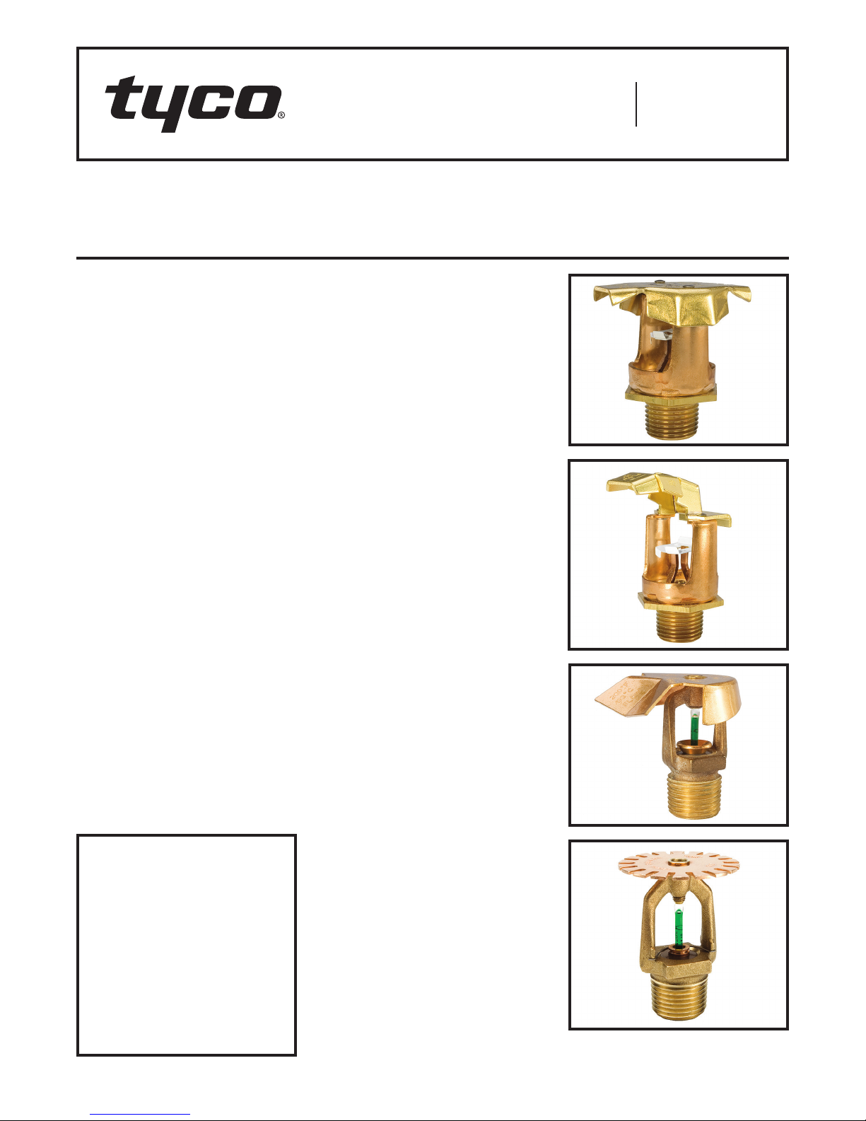
The TYCO Models Back to Back Dual
Directional (BB), Single Directional (SD),
HIP, and Attic Plus (AP) Specific Application Attic Sprinklers for Protecting
Attics are fire sprinklers for combustible and non-combustible sloped attic
spaces.
While Models BB, SD, and HIP are
specific application attic sprinklers,
the Model AP is a specific application
combustible concealed-space sprinkler with specific application criteria
for use with Models BB, SD, and HIP
in attic spaces.
Specific Application Attic Sprinklers
provide superior fire protection in attic
spaces. When compared to Standard Spray Sprinklers, cost savings
are achieved by eliminating branchline
materials and the associated installation labor.
Specific Application Attic Sprinklers for
Protecting Attics have undergone the
most extensive fire testing ever performed for sloped attic spaces. They
are UL Listed with their specific application guidelines for use as special
sprinklers as defined by the NATIONAL
FIRE PROTECTION ASSOCIATION
(NFPA).
Specific Application Attic Sprinklers
provide an extended coverage spacing
alternative to the restricted spacing of
Standard Spray Sprinklers.
IMPORTANT
Refer to Technical Data Sheet
TFP2300 for warnings pertaining to
regulatory and health information.
Always refer to Technical Data
Sheet TFP700 for the “INSTALLER
WARNING” that provides cautions
with respect to handling and installation of sprinkler systems and components. Improper handling and
installation can permanently damage
a sprinkler system or its components and cause the sprinkler to fail
to operate in a fire situation or cause
it to operate prematurely.
The Specific Application Attic Sprinklers are the first sprinklers to be:
• Listed for extended coverage in combustible construction
• Full-scale fire tested in both wet and
dry system scenarios
• Full-scale tested for use in wood
truss construction
• Listed for specific roof slopes (Ref.
Table A )
The Specific Application Attic Sprinklers provide cost control with the
best level of protection by eliminating the need for additional sprinklers
and branchline piping. In many cases,
an attic can be entirely protected with
just one line of piping located below the
peak of the roof using Model BB Sprinklers. If Model SD Sprinklers or Model
HIP Sprinklers are needed, one line of
either at each area being covered is
sufficient.
For example, while using Standard
Spray Sprinklers, a system in a 60 ft
(18,3 m) wide attic with up to a 12:12
roof pitch designed to NFPA 13, could
require seven branchlines to cover the
main portion of the attic and several
additional branchlines to cover the hip
areas. With Specific Application Attic
Sprinklers, the required coverage can
be obtained with just one branchline
running below the peak and one down
each slope of the hip beam. This would
result in approximately 90% less pipe
needed for installation. This reduction
in the number of branchlines saves the
cost of the pipe, fittings, hangers, and
associated labor by eliminating up to
five branchlines.
Another important aspect of the Specific Application Attic Sprinkler technology, which also allows for cost savings,
is the reduction in system volume. This
volume reduction may result in reducing the size of a dry pipe valve and air
compressor, and possibly allows for
quicker water delivery times, eliminating the need for an accelerator.
Page 1 of 28 AUGUST 2018 TFP610
Page 2
TFP610
SECTION ELEVATION
ELEVATION
SECTION
1
ELEVATION
SECTION
FRAME
FLOW
SECTION ELEVATION
10
Page 2 of 28
Components:
-
Frame
1
-
Button
2
-
Sealing
3
Assembly
2-1/4"
(57,2 mm)
1-1/8"
(28,6 mm)
FLOW FLOW
4
1
3
CROSS
5
THREAD
1/2" (12,7 mm)
(54,0 mm)
2
RELIEF
NOMINAL
MAKE-IN
-
Bulb
4
-
Compression
5
Screw
-
Deector
6
6
2-1/8"
13/16"
(20,6 mm)
WRENCH
FLATS
1-5/8"
(41,3 mm)
3/4" NPT
FRAME
ARMS
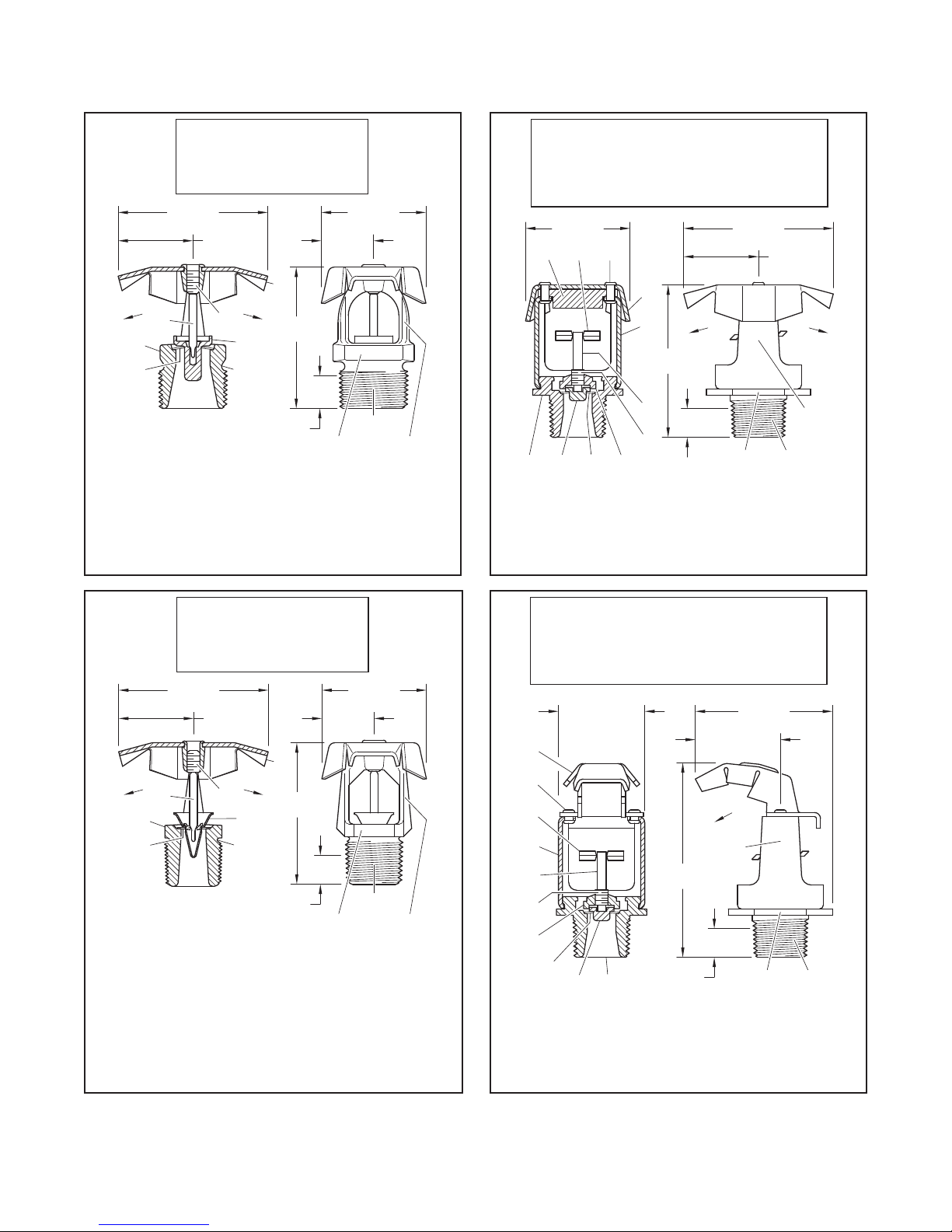
FIGURE A
MODELS BB1, BB2, AND BB3 WITH 8.0 K-FACTOR
SPECIFIC APPLICATION ATTIC SPRINKLERS
Components:
-
1
-
2
-
3
-
4
1-9/16"
(39,7 mm)
10
2
CROSS
Body
Cap
Sealing
Assembly
Saddle
11
3
-
Compression
5
Screw
Lever
6
-
Deector
7
Frame
9
8
FLOW FLOW
7
2-1/2"
(63,5 mm)
6
5
4
(11,1 mm)
NOMINAL
MAKE-IN
7/16"
WRENCH
8
9
10
11
2-1/4"
(57,2 mm)
HEX
-
Deector
-
Rivet
--
Diffuser
-
Link
Assembly
1-1/8"
(28,6 mm)
1/2"
NPT
FRAME
ARMS
FIGURE B
MODELS BB1, BB2, AND BB3 WITH 5.6 K-FACTOR
SPECIFIC APPLICATION ATTIC SPRINKLERS
Components:
-
Frame
1
-
Button
2
-
Sealing
3
Assembly
2-1/4"
(57,2 mm)
1-1/8"
(28,6 mm)
4
1 2
3
CROSS
5
7/16" (11,1 mm)
FLOW
THREAD
(54,0 mm)
RELIEF
NOMINAL
MAKE-IN
-
Bulb
4
-
Compression
5
Screw
-
Deector
6
6
2-1/8"
13/16"
(20,6 mm)
WRENCH
FLATS
1-5/8"
(41,3 mm)
1/2" NPT
ARMS
FIGURE C
MODELS BB1, BB2, AND BB3 WITH 4.2 K-FACTOR
SPECIFIC APPLICATION ATTIC SPRINKLERS
Components:
(54,0 mm)
1-5/16"
WRENCH
-
8
-
9
--
10
2-1/8"
HEX
Deector
Rivet
Link
Assembly
1/2"
NPT
8
9
7
6
5
4
-
1
-
2
-
3
-
4
3
Body
Cap
Sealing
Assembly
Saddle
1-5/16"
(33,3 mm)
2 1
CROSS
-
Compression
5
Screw
Lever
6
-
Deector
7
Frame
3"
(76,2 mm)
7/16" (11,1 mm)
NOMINAL
MAKE-IN
(33,4 mm)
FLOW
FRAME
ARMS
FIGURE D
MODELS SD1, SD2, AND SD3 WITH 5.6 K-FACTOR
SPECIFIC APPLICATION ATTIC SPRINKLERS
Page 3
TFP610
SECTION ELEVATION
SECTION ELEVATION
2
1
3
4
5
6
(57,2 mm)
Page 3 of 28
Components:
1
3
2-1/8"
(54,0 mm)
4
CROSS
-
Frame
1
-
Button
2
-
Sealing
3
Assembly
1-1/16"
(27,0 mm)
5
2
THREAD
RELIEF
7/16" (11,1 mm)
4
5
6
6
2-1/8"
(54,0 mm)
NOMINAL
MAKE-IN
-
Bulb
-
Compression
Screw
-
Deector
1-1/4"
(31,8 mm)
FLOW
WRENCH
FLATS
2"
(50,8 mm)
1/2" NPT
FRAME
ARMS
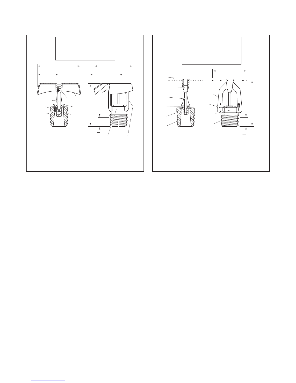
FIGURE E
MODEL HIP WITH 5.6 K-FACTOR
SPECIFIC APPLICATION ATTIC SPRINKLERS
MODEL AP WITH 4.2 OR 5.6 K-FACTOR SPECIFIC
APPLICATION COMBUSTIBLE CONCEALED
Components:
-
1
-
2
-
3
-
4
CROSS
Frame
Sealing
Assembly
Button
Bulb
SPRINKLER
FRAME
ARMS
WRENCH
FLATS
1/2" NPT
FIGURE F
-
Compression
5
Screw
-
Deector
6
-
Ejection
7
Spring
1-11/16"
(42,9 mm)
7
7/16" (11,1 mm)
NOMINAL MAKE-IN
2-1/4"
SPACE SPRINKLERS
Another cost reduction is the Listing of
BLAZEMASTER CPVC for use in attic
spaces to feed the wet system Specific
Application Attic Sprinklers for Protecting Attics, as well as to feed the wet
system sprinklers below the ceiling.
Traditionally, BLAZEMASTER CPVC
has been used on the lower floors in
the joist space above a ceiling that
do not require sprinklers. The cost of
using CPVC on those floors can now
be translated to the upper floor even if
sprinklers are required in the attic.
There are four models of the Specific
Application Attic Sprinklers used for
protecting attics: BB, SD, HIP, and AP.
The Model BB and Model SD Sprinklers
have three separate versions used for
different roof pitches. The pitches, as
applicable, can vary from a minimum of
3:12 to a maximum of 12:12. For more
information, refer to Table A.
BB Sprinkler
(Back to Back Dual Directional)
The Model BB Specific Application
Attic Sprinkler, as seen in Figure A,
B and C, throws a narrow and long
pattern. The narrow spacing along
the ridge serves two purposes: the
response time is reduced by placing
the sprinklers no farther than 6 ft
(1,8 m) apart, and the spray can be
concentrated in the throw direction to
obtain a pattern that will cover up to
30 ft (9,1 m) in each direction when
measured horizontally.
There are three different models that
account for different roof slopes: BB1,
BB2, and BB3. Each model is provided
in one of three different orifice sizes:
K=4.2, 5.6, or 8.0.
SD Sprinkler (Single Directional)
The Model SD Specific Application
Attic Sprinkler, as seen in Figure D,
throws a narrow but long pattern like
the Model BB. However, unlike the
Model BB, the Model SD only throws
in one direction.
Model BB Sprinklers are primarily used
where shear walls or draft curtains have
been installed within an attic space.
Model BB Sprinklers are also used
when the framing direction is parallel
with the outside wall in the hip area.
For more information, refer to Figure
13. In this case, the SD Model Sprinkler
would be used on one side of the slope
and AP Sprinklers or Standard Spray
Sprinklers would be used to protect the
other side.
The Model SD Sprinklers must be
installed in a vertical upright orientation
and not angled with the slope. Achieving the vertical upright orientation may
require the use of a swing joint if the
SD Sprinklers are being fed from a line
running along and parallel to the roof
hip.
There are three different models that
account for different roof slopes: SD1,
SD2, and SD3.
HIP Sprinkler
The Model HIP Specific Application
Attic Sprinkler, as seen in Figure E,
covers the area of the hip in the attic.
This is a slightly different concept than
the BB Model or SD Model Sprinklers.
The HIP Sprinkler is located along
the slope running down the hip, and
throws a 90° pattern toward the outside
eaves. This pattern allows the water to
“corner” and control the fire.
The HIP does not throw much water
directly up or down the hip, but rather it
throws most of the pattern out to each
side (90°) down the slope of the roof.
This sprinkler is typically spaced 6 ft
(1,8 m) to 3 ft (0,9 m) on center down
the slope.
To use the HIP Sprinkler, the framing
must be perpendicular to the outside
wall (refer to Figure 12) and the
maximum throw cannot exceed 28 ft
(8,5 m) measured horizontally. The HIP,
unlike the BB Model and SD Model, is
installed with the deflector parallel with
the slope. There is only one model with
flows and pressures for two different
spacings.
Page 4

TFP610
Page 4 of 28
AP Sprinkler (Attic Plus)
The AP Specific Application Attic Sprinkler are to be installed in the upright
orientation with their deflector parallel
to the roof. The Model AP Sprinklers,
as seen in Figure F, are intended to
be used to provide protection of attic
areas outside the scope of applications for the BB, SD, or HIP Sprinklers.
The AP Sprinklers must only be used in
conjunction with other Specific Application Attic Sprinklers (BB, SD, and
HIP), or as permitted in other sections
of this document. The AP Sprinklers
will provide a hydraulic advantage over
Standard Spray Sprinklers for the protection of attic areas outside the scope
of application for the BB Model, SD
Model, or HIP Model Sprinklers.
NOTICE
The Specific Application Attic Sprinklers for Protecting Attics described
herein must be installed and maintained
in compliance with this document, as
well as with the applicable standards
of NFPA, in addition to the standards of
any other authorities having jurisdiction.
Failure to do so may impair the performance of these devices.
The owner is responsible for maintaining their fire protection system
and devices in proper operating condition. Contact the installing contractor or product manufacturer with any
questions.
Sprinkler
Identification
Number (SIN)
TY4180* BB1 K= 8.0
TY4181* BB2 K= 8.0
TY4182* BB3 K= 8.0
TY3180* BB1 K= 5.6
TY3181* BB2 K = 5.6
TY3182* BB3 K = 5.6
TY2180 BB1 K= 4.2
TY2181 BB2 K=4. 2
TY2182 BB3 K=4.2
TY3183* SD1 K= 5.6
TY3184* SD2 K= 5.6
TY3185* SD3 K= 5.6
TY3187* HIP K= 5.6
TY3190 AP K= 5.6
TY2190 AP K= 4.2
* The “TY” prefix is a re-designation of
the previous “C” prefix. For example,
TY4180 is a re-designation for C4180.
Technical
Data
Approvals
UL and C-UL Listed
These Approvals only apply to the service
conditions indicated in the Design Criteria
section on Page 6 and the Design Guidelines
section on Page 8.
Pipe Thread Connection
1/2 inch NPT for K= 4.2 and 5.6
3/4 inch NPT for K= 8.0
Discharge Coefficient
K = 4.2 GPM/psi½ (60,5 LPM/bar½)
K = 5.6 GPM/psi½ (80,6 LPM/bar½)
K = 8. 0 GPM /psi½ (115,5 LPM/bar½)
Temperature Rating
Intermediate Temperature as follows:
–200°F ( 93°C) for BB (K4.2 and K8.0),
H I P, A P
–212°F (100°C) for BB ( K5.6), SD
Finish
Natural Brass
Physical Characteristics
(Figures A, C and E)
Frame . . . . . . . . . . . . . . . . . . . . . . . . . . . .Bronze
Button .....................Bronze/Copper
Sealing Assembly ..Ber yllium Nickel w/TEFLON
Bulb .....................Glass (3 mm dia.)
Link . . . . . . . . . . . . . . . . . . . . . . . . . . . . . MONEL
Compression Screw . . . . . . . . . . . . . . . . . .Brass
Deflector . . . . . . . . . . . . . . . . . . . . Brass /Bronze
Physical Characteristics
(Figures B and D)
Body . . . . . . . . . . . . . . . . . . . . . . . . . . . . . .Brass
Cap . . . . . . . . . . . . . . . . . . . . . . . . . . . . . . Bronze
Sealing Assembly ..Ber yllium Nickel w/TEFLON
Saddle . . . . . . . . . . . . . . . . . . . . . . . . . . . . . Brass
Link Assembly . . . . . . . . . . . . . . . . . . . . . . Nickel
Compression Screw . . . . . . . . . . . . . . . . . .Brass
Deflector . . . . . . . . . . . . . . . . . . . . Brass /Bronze
Lever .....................Bronze Deflector
Frame . . . . . . . . . . . . . . . . . . . . . . . . . . . .Bronze
Diffuser . . . . . . . . . . . . . . . . . . . . . . . . . . . .Brass
Rivet . . . . . . . . . . . . . . . . . . . . . . . . . . . . . .Brass
Physical Characteristics
(Figure F)
Frame . . . . . . . . . . . . . . . . . . . . . . . . . . . . . Brass
Button . . . . . . . . . . . . . . . . . . . . . . . . . . . .Bronze
Sealing Assembly ..Ber yllium Nickel w/TEFLON
Bulb .....................Glass (3 mm dia.)
Compression Screw . . . . . . . . . . . . . . . . . .Brass
Deflector . . . . . . . . . . . . . . . . . . . . . . . . . .Bronze
Operation
BB (K=8.0 and 4.2), HIP (K=5.6) and
AP (5.6 and 4.2)
The glass bulb contains a fluid that
expands when exposed to heat. When
the rated temperature is reached, the
fluid expands sufficiently to shatter the
glass bulb, allowing the sprinkler to
activate and water to flow.
BB (K=5.6) and SD (K=5.6)
The fusible link assembly is comprised
of two link halves which are joined by
a thin layer of solder. When the rated
temperature is reached, the solder
melts and the two link halves separate,
allowing the sprinkler to activate and
water to flow.
Page 5
Installation
"A" ONLY
"A" ONLY
"A" ONLY
"A" ONLY
The TYCO Specific Application Attic
Sprinklers for Protecting Attics must
be installed in accordance with this
section.
NOTICE
Do not install any bulb-type sprinkler
if the bulb is cracked or there is a loss
of liquid from the bulb. With the sprinkler held horizontally, a small air bubble
should be present. The diameter of the
air bubble is approximately 1/16 inch
(1,6 mm) for the 155°F (68°C) and 3/32
inch (2,4 mm) for the 200°F (93°C) temperature ratings.
A leak-tight 1/2 inch NPT sprinkler joint
should be obtained by applying a minimum-to-maximum torque of 7 to 14
lb-ft ( 9,5 to 19,0 N·m). Higher levels of
torque can distort the sprinkler inlet
with consequent leakage or impairment
of the sprinkler.
To install the Specific Application Attic
Sprinklers, complete the following:
Step 1. Sprinklers must be oriented
correctly as follows:
• Model BB Sprinklers are to be
installed in the upright vertical position with the flow arrows on the
deflector pointing down the two
opposing slopes.
• Model SD Sprinklers are to be
installed in the upright vertical position with the flow direction arrow
on the deflector pointing down the
slope.
• The Model HIP Sprinklers are to be
installed with the deflector at the top,
the sprinkler centerline perpendicular
to the ridge of the hip roof, and the
flow direction arrows on the deflector pointing down the two opposing slopes. Unlike the Model BB and
Model SD, the Model HIP is installed
angled so that its deflector is parallel with the slope of the hip ridge line.
• The Model AP Sprinklers are to be
installed in the upright position with
the deflector parallel to the roof
slope. There are no flow arrows on
the deflector to consider; however, a
good piping practice is to position all
the Model AP Sprinklers so that their
frame arms are in the same direction.
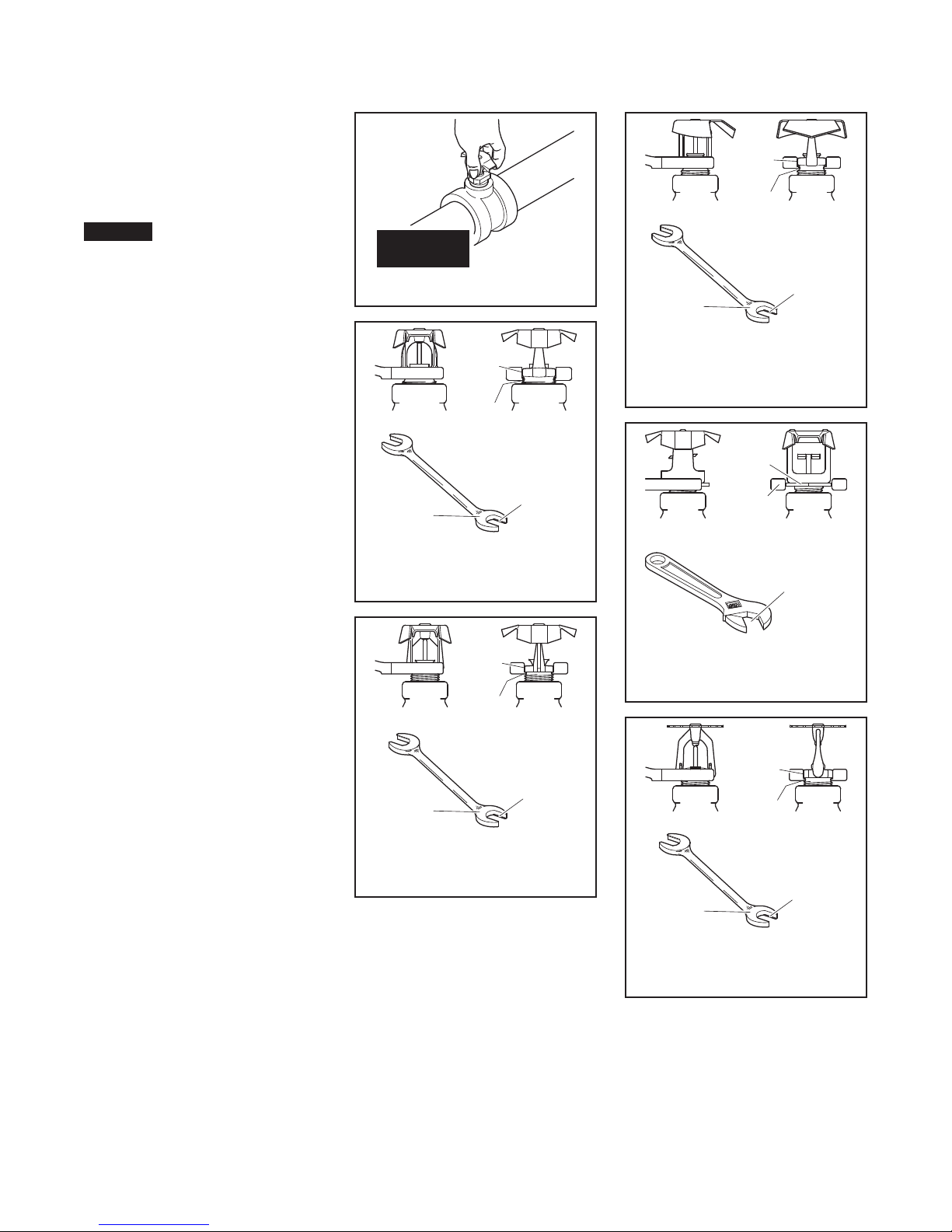
DO NOT
DO NOT GRASP DEFLECTOR
USE END
MARKED
W-TYPE 3 SPRINKLER WRENCH
BB (K=8.0) SPRINKLERS’
USE END
MARKED
W-TYPE 6 SPRINKLER WRENCH
Step 2. With pipe thread sealant
applied to the pipe threads, handtighten the sprinkler into the sprinkler
fitting.
Note: With reference to Figure G, do
not grasp the sprinkler by the deflector.
Step 3. Wrench-tighten the sprinkler using only the wrenches shown
in Figures H through M. Wrenches
are only to be applied to the sprinkler wrench flats or wrench hex, as
applicable.
FIGURE G
WRENCH
FLATS
ENGAGE
SPRINKLER
THREAD RELIEF
WITH WRENCH
JAW FLANGES
WRENCH
JAW FLANGE
FIGURE H
FOR USE WITH
WRENCH
FLATS
ENGAGE
SPRINKLER
THREAD RELIEF
WITH WRENCH
JAW FLANGES
WRENCH
JAW FLANGE
FIGURE J
For Use with
BB (K= 4.2) Sprinklers
TFP610
Page 5 of 28
WRENCH
FLATS
ENGAGE
SPRINKLER
THREAD RELIEF
WITH WRENCH
JAW FLANGES
WRENCH
HEX
WRENCH JAW
TO FIT WRENCH
WRENCH
FLATS
ENGAGE
JAW FLANGE
ADJUST
HEX
WRENCH
JAW FLANGE
USE END
MARKED
FIGURE K
W-T Y P E 2 0
SPRINKLER WRENCH
For Use with
HIP (K= 5.6) Sprinklers
WRENCH
APPLY
WRENCH
TO WRENCH
HEX ONLY
FIGURE L
ADJUSTABLE WRENCH
For Use with BB ( K= 5.6) and
SD (K= 5.6) Sprinklers
SPRINKLER
THREAD RELIEF
WITH WRENCH
JAW FLANGES
USE END
MARKED
FIGURE M
W-TYPE 6 SPRINKLER WRENCH
For Use with
AP (K= 4.2 and 5.6) Sprinklers
Page 6

TFP610
Page 6 of 28
Design
Criteria
Area of Use
The TYCO Specific Application Attic
Sprinklers are designed for use in
roof structures and combustible and
non-combustible sloped attic spaces,
including wood joist/rafters and wood
trussed attics with a ceiling below.
System Type for
BB, SD, HIP, or AP Sprinklers
Wet using CPVC pipe
Wet or dry using steel pipe
Note: Use of the 4.2 K sprinklers in dry
pipe systems is permitted by NFPA 13
where piping is corrosion resistant or
internally galvanized.
Hazard
Light Hazard.
BB, SD, or HIP Allowable Roof Span
(Coverage) and Roof Pitch
Refer to Table A for allowable roof
spans and roof pitches, and for the
associated minimum sprinkler flows
and pressures. Figures 1, 2, 11 and 12
illustrate where the roof span is to be
measured.
Coverage Beyond BB, SD or HIP
Allowable Roof Spans
Up to 10 ft (3,1 m) of coverage at the
eave(s) beyond the allowable roof
spans for BB, SD, or HIP Sprinklers
may be obtained by using a single row
of AP Sprinklers. For more information,
refer to Figure 14A, 14B, and 15.
BB, SD, HIP, or AP Minimum
Distance Between Sprinklers
4 ft (1,2 m) as measured along the
branchline for BB and SD. For more
information, refer to Figure 3.
3 ft (0,9 m) as measured along the
branchline for HIP. For more information, refer to Figure 12.
7 ft (2,1 m) between AP Sprinklers.
BB, SD, HIP, or AP Maximum
Distance Between Sprinklers
6 ft (1,8 m) on center along the branchline for BB, SD, and HIP. For more information, refer to Figure 3 and 12.
For AP, the maximum spacing is
10 ft (3,1 m) perpendicular to slope and
12 ft (3,6 m) parallel to slope. When
there is more than one row of AP Sprinklers, the sprinklers must be staggered
as seen in Figure 20-B-3.
BB, SD, HIP, or AP Minimum
Distance to AP Sprinklers or
Standard Spray Sprinklers
As measured along the peak/ridge
direction, 6 ft (1,8 m) from BB, SD, and
HIP to Standard Spray Sprinklers. For
more information, refer to Figure 4.
As measured along the peak/ridge
direction, 7 ft (2,1 m) from AP to Standard Spray Sprinklers. For more information, refer to Figure 4.
In the slope direction, 26 ft (7,9 m) from
BB or HIP Sprinklers to AP Sprinklers
or Standard Spray Sprinklers. For more
information, refer to Figure 6.
BB, SD, or HIP Deflector Installation
Position Below Peak/Ridge or Deck
For roof pitches of 4:12 (33%) to 12:12
(100%), 22 in. (558,8 mm) maximum
and 16 in. (406,4 mm) minimum. For
more information, refer to Figure 2 and
5.
For roof pitches of 3:12 (25%) up to
4:12 (33%), (only 4.2K Model BB),
12 in. (304,8 mm) maximum below the
peak and a minimum of 1 in. (25,4 mm)
below the bottom of the top chord or
solid wood rafter.
AP Deflector Position and
Roof Pitch
1 to 3 in. (25,4 to 75,6 mm) below the
bottom of the top chord or bottom of
solid wood rafter, where the roof pitch
is 3:12 to 12:12 and the top chord or
solid wood rafter is a nominal 12 in.
(600 mm) or less.
BB or SD Deflector Installation
Position Above Scissor Truss
18 in. (457,2 mm) minimum. For more
information, refer to Figure 5.
BB, SD, or HIP Minimum Distance
Away from Trusses
Attic Sprinklers must be installed
6 in. (152,4 mm) away from the face of
trusses. For more information, refer to
Figure 7.
SD Distance from Shear Wall or
Draft Curtain
4 to 6 in. (101,6 to 152,4 mm) from face,
and a minimum of 8 in. (203,2 mm)
above the bottom of the draft curtain.
For more information, refer to Figure 2.
Draft Curtains
Draft curtains installed to permit the
installation of Attic Sprinklers shall be
constructed so as to not allow heat
to escape through or above the draft
curtain. The draft curtain may be constructed of 1/2 in (12,7 mm) plywood.
BB or HIP Maximum Distance from
the Center Line of the Ridge
6 in. (152,4 mm) with the deflector
located 16 to 22 in. (406,4 mm to 558,8
mm) from the peak. For more information, refer to Figure 8.
Use of UL Listed BLAZEMASTER
CPVC Piping with Specific
Application Attic Sprinklers for
Protecting Attics (Wet Systems
Only)
BLAZEMASTER CPVC piping may
be used in a combustible concealed
attic space requiring sprinklers when
installed in accordance with the following guidelines:
Note: Where the use of non-combustible insulation is specified, verify
with the insulation manufacturer as to
the non-combustibility of the insulation. The non-combustible insulation
(fiberglass) may be faced or unfaced.
Where faced, the facing need not be
non-combustible. The insulation is to
have a flame spread index of not more
than 25.
Verify chemical compatibility of the
insulation with BLAZEMASTER CPVC
by consulting www.lubrizol.com.
• BLAZEMASTER CPVC may be used
to feed the wet system ceiling sprinklers on the floor below. There must
be 6 in. (152,4 mm) of non-combustible insulation covering the horizontal or vertical pipe extending 12 in.
(304,8 mm) on each side away from
the centerline of the pipe. Refer to
Figures 9A, 9B, and 9C. The area
above the pipe must be protected
by BB, SD, HIP, or AP Sprinklers. For
more information, refer to Figure 9A.
If the pipe is located inside the ceiling joist, the joist channel must be
covered or filled with 6 in. (152,4 mm)
of non-combustible insulation on top
of the pipe and the area above must
be protected by BB, SD, HIP, or AP
Sprinklers. For more information,
refer to Figure 9B. Insulation is for re
protection purposes. It is not freeze
protection. BLAZEMASTER CPVC
must be installed in accordance with
the BLAZEMASTER installation guide
instructions.
• With reference to Figure 19, BLAZEMASTER CPVC may be used
exposed to feed wet system BB, SD,
or HIP Sprinklers where:
•
Risers are vertical and protected
by BB, SD, or HIP Sprinklers located at a maximum lateral distance
of 12 in. (304,8 mm) from the riser
centerline.
•
BB, SD, or HIP Sprinklers are directly mounted on the branchline.
•
BB, SD, or HIP Sprinklers are on
arm-overs and located at a maximum lateral distance of 6 in.
(152,4 mm) from the branchline
centerline.
•
BB, SD, or HIP Sprinklers are on
vertical sprigs attached to the
branchline.
Page 7
Page 7 of 28
DRY PIPE
SYSTEM
MAXIMUM
WATER
DELIVERY
Seconds
MODEL K SIN
ALLOWABLE
ROOF SPAN,
(a) (b) (e)
Feet (m)
MINIMUM
FLOW,
GPM (LPM)
MINIMUM
PRESSURE,
psi (bar)
PITCH,
Rise Over Run (%)
BB1 8.0 T Y4180 ≤60 (18,3) 38 (14 4) 22.6 (1,5) 4:12 (33) to less than 7:12 (58) (c)
BB2 8.0 TY4181 ≤60 (18,3) 38 (144 ) 22.6 (1,5) 7:12 (58) to less than 10:12 (83) (c)
BB3 8.0 T Y4182 ≤60 (18,3) 40 (152) 25.0 (1,7 ) 10:12 (83) to 12:12 (100) (c)
BB1 5.6 T Y3180 >40 (12,2) to ≤60 (18,3) 38 (14 4) 46.0 (3,2) 4:12 (33) to less than 7:12 (58) (c)
BB2 5.6 TY3181 >40 (12,2) to 60 (18,3) 38 ( 144) 46.0 (3,2) 7:12 (58) to less than 10:12 (83) (c)
BB3 5.6 T Y3182 >40 (12,2) to 60 (18,3) 38 (144) 46.0 (3,2) 10:12 (83) to 12:12 (100) (c)
BB1 5.6 T Y3180 ≤40 (12,2) 25 (95) 20.0 (1,4) 4:12 (33) to less than 7:12 (58) (c)
BB2 5.6 TY3181 ≤40 (12,2) 25 (95) 20.0 (1,4) 7:12 (58) to less than 10:12 (83) (c)
BB3 5.6 T Y3182 ≤40 (12,2) 25 (95) 20.0 (1,4) 10:12 (83) to 12:12 (100) (c)
BB1 4.2 T Y2180 ≤20 (6,1) 13 (4 9) 9.6 (0,7) 3:12 (25) to less than 7:12 (58) 45 (d)
BB2 4.2 T Y2181 ≤20 (6,1) 13 (49) 9.6 (0,7) 7:12 (58) to less than 10:12 (83) 45 (d)
BB3 4.2 T Y2182 ≤20 (6,1) 13 (4 9) 9.6 (0,7) 10:12 (83) to 12:12 (100) 45 (d)
SD1 5.6 T Y318 3 >30 (9,1) to ≤40 (12,2) 35 (132) 39.0 (2,7) 4:12 (33) to less than 7:12 (58) (c)
SD2 5.6 T Y3184 >30 (9,1) to ≤40 (12,2) 35 (13 2) 39.0 (2,7 ) 7:12 (58) to less than 10:12 (83) (c)
SD3 5.6 T Y3185 >30 (9,1) to ≤40 (12,2) 35 (132) 39.0 (2,7 ) 10:12 (83) to 12:12 (100) (c)
SD1 5.6 T Y318 3 >10 (3,0) to ≤30 (9,1) 25 (95) 20.0 (1,4) 4:12 (33) to less than 7:12 (58) (c)
SD2 5.6 T Y3184 >10 (3,0) to ≤30 (9,1) 25 (95) 20.0 (1,4) 7:12 (58) to less than 10:12 (83) (c)
SD3 5.6 T Y3185 >10 (3,0) to ≤30 (9,1) 25 (95) 20.0 (1,4) 10:12 (83) to 12:12 (100) (c)
SD1 5.6 T Y318 3 ≤10 (3,0) 19 (72) 11.5 (0,8) 4:12 (33) to less than 7:12 (58) (c)
SD2 5.6 T Y3184 ≤10 (3 ,0) 19 ( 72) 11.5 (0,8) 7:12 (58) to less than 10:12 (83) (c)
SD3 5.6 T Y3185 ≤10 (3,0) 19 ( 72) 11.5 (0,8) 10:12 (83) to 12:12 (100) (c)
HIP 5.6 T Y3187 >20 (6,1) to ≤28 (8,5) 3 4 (129 ) 36.9 (2,5) 4:12 (33) to 12:12 (100) (c)
HIP 5.6 T Y3187 ≤20 (6,1) 25 (95) 20.0 (1,4) 4:12 (33) to 12:12 (100) (c)
AP 5.6 TY319 0
AP 4.2 TY219 0 3:12 (25) to 12:12 (100) 60 (d)
NOTES
a. T he BB and S D roof spa n is measured ho rizont ally (no t along th e slope) a s shown in F igure 1 an d Figure 2.
b. The HIP roof span is mea sured h orizontally as shown in Fi gure 2.
c. R efer to NFPA 13.
d. Maximum water delive ry tim e for all sy stem size s.
e. T he AP roo f span is measured along the slop e. Maxi mum 10 ft (3, m) p erpendicul ar to slop e by maxi mum 12 ft (3,6 m) p arall el to slop e.
10 (3,1) x 12 (3,6)
-See note (e)
Minimum 7 psi (0,48 bar)
Minimum 0.10 gpm/ft2
(4,1 mm/min.) Design Density
3:12 (25) to 12:12 (100) 60 (d)
TFP610
TIME,
ALLOWABLE ROOF SPAN, FLOW, PRESSURE, AND PITCH FOR
SPECIFIC APPLICATION SPRINKLERS FOR PROTECTING ATTICS
TABL E A
Page 8

TFP610
Page 8 of 28
•
BB, SD, or HIP Sprinklers are on
arm-over or angled sprigs, and located at a maximum lateral distance of 6 in. (152,4 mm) from the
branchline centerline.
•
A minimum lateral distance of
18 in. (450 mm) is maintained between the CPVC pipe and a heat
producing device such as heat
pumps, fan motors, and heat
lamps.
• BLAZEMASTER CPVC may be used
exposed to provide wet system, vertical or angled, sprigs to AP Sprinklers (refer to Figures 17A and 17B)
where:
• The exposed portion of an angled
sprig is a maximum length of 3 ft
(0,9 m), the sprig is supported adjacent to the AP Sprinkler, and vertical restraint is provided using the
CPVC hanger support for horizontal pipe runs.
•
Vertical sprigs have a maximum
exposed length of 10 ft (3,05 m),
the AP Sprinkler is located at a
maximum lateral distance of 12 in.
(3304,8 mm) from the sprig centerline, and the sprig is supported at
the swing joint to the AP Sprinkler.
•
A minimum 6 in. (152,4 mm) deep
of non-combustible insulation extending 12 in. (304,8 mm) on each
side away from the centerline of
the CPVC branchline feeding the
AP sprigs (refer to Figure 17A). If
the CPVC branchline is located inside the ceiling joist, the joist channel must be covered or lled with a
minimum of 6 in. (152,4 mm) deep
of noncombustible insulation on
top of the branchline feeding the
AP sprigs (refer to Figure 17B). Insulation is for re protection purposes. It is not freeze protection.
Additional depth of non-combustible insulation may be added to reduce the exposed length of the AP
sprigs.
•
A minimum lateral distance of
18 in. (450 mm) is maintained between the CPVC pipe and a heat
producing device such as heat
pumps, fan motors, and heat
lamps.
Mismatched Slopes
Refer to Figure 10.
Obstructions
For BB, SD, and HIP, refer to Figure 16.
For AP Sprinklers, refer to Figure 18.
BB, SD, HIP, and AP Sprinklers may
be installed directly on maximum 2-1/2
inch NPS (DN65) branch lines without
the need for sprigs. See NFPA 13 for
requirements when installed on pipe
greater than 2-1/2 inch NPS (DN65).
Hydraulic Requirements
Refer to Figure 20.
Determine the Correct Flow and
Pressure
For BB, SD, or HIP Sprinklers, determine the roof span (measured horizontally) and the slope of the roof, and then
refer to Table A. There is no interpolation of the flow and pressure shown.
Round all cases to the next higher
spacing. For example, a 45 ft (13,7 m)
span with the BB1 (K=8.0) would be
calculated at the 60 feet (18,3 m) span.
For the AP Sprinklers, the minimum
design pressure is 7 psi, and
the minimum design density is
0.10 gpm/ft² (4,1 mm/min). The NFPA
13, 20 psi (1,4 bar) minimum operating
pressure for Standard Spray Sprinkler
spacings parallel to the ridge that are
above 8 ft (2,4 m) does not apply to the
A P.
Coverage Area
• Coverage area for the BB Sprinklers
is determined by twice the distance
of the furthest throw measured along
the slope multiplied by the distance
along the branchline. The maximum
distance along branchline is 6 ft
(1,8 m) regardless of the length of the
throw.
Note: The distance along the branchline may have to be reduced to less
than the maximum of 6 ft (1,8 m) to
remain under 400 ft² (37,2 m²) maximum
depending on the slope and the span.
In no case can the span exceed 60 ft
(18,3 m) without additional Standard
Spray Sprinklers.
• Coverage area for the SD (Single
Directional) Sprinklers is the distance
along the branchline multiplied by
the distance of the throw down the
slope. Regardless of the throw, the
maximum distance along the branchline is 6 ft (1,8 m), the maximum
throw measured horizontally is 40 ft
(12,2 m), and the maximum coverage
per sprinkler is 400 ft² (37,2 m²).
• Coverage area for the HIP Sprinklers
is the distance down the larger slope
multiplied by two, and multiplied by
the distance between the sprinklers
as measured along the slope of the
hip.
• Coverage area for the AP (Attic Plus)
Sprinklers is the distance along the
branchline multiplied by the distance
between the branchlines. The maximum spacing is 10 ft (3,1 m) perpendicular to the slope and 12 ft
(3,6 m) parallel to slope, and as measured on the slope. When there is
more than one row of AP Sprinklers,
the sprinklers must be staggered per
Figure 20-B-3. The maximum spacing per sprinkler is 120 ft² (11,1 m²).
Design
Guidelines
To design a project with the TYCO Specific Application Attic Sprinklers, use
these steps as a guideline:
• Determine if single, dual directional
or hip sprinkler is needed.
• Determine the roof slope is between
3:12 to 12:12. If more than one slope
is being used on a project, select the
correct sprinkler for each area.
• Follow the guidelines for each type
of sprinkler.
• Calculate the sprinkler system in
accordance with the appropriate flow
and pressure information provided in
Table A, as well as Figure 20. There
is no interpolation of the flows and
pressures shown on the chart.
For BB Sprinklers
(Back to Back Dual Directional)
• Verify the framing direction is perpendicular to the outside wall (refer
to Figure 12). If not, cover that area
with AP Sprinklers or Standard Spray
Sprinklers (refer Figure 13).
• Determine the throw needed. For
more information, see the spacing requirements in Table A. If over
20 ft (6,1 m) and up to 60 ft (18,3 m)
is required, use the 8.0 K-factor, BB
Sprinklers to reduce the pressure
required. If pressure is not a concern,
use the 5.6 K-factor, BB Sprinklers to
minimize over discharge.
• If less than 20 ft (6,1 m) is required,
use the 4.2 K-factor, Back to Back
Dual Directional to minimize pressure
and flow requirements.
• Determine the distance along the
slope. If the distance is not equal,
use the longer side. Multiply the longer side by two to determine the
spacing down the slope. Four hundred divided by this value will determine the maximum spacing along
the ridge. The maximum distance
is 6 ft (1,8 m). For example, a 12:12
slope at the maximum span of 60 ft
(18,3 m) will produce a slope length
of approximately 42.5 ft (13,0 m).
That number multiplied by two produces an 85 ft (25,9 m) throw. A
400 ft² maximum divided by an
85 ft (25,9 m) throw only allows a
4 ft 8 in. (1,4 m) spacing along the
ridge. Using the maximum spacing,
space the sprinklers along the ridge.
• Avoid obstructions as shown in Figure 16. If necessary, add Model AP
Sprinklers or Standard Spray Sprinklers to maintain coverage around
obstructions.
Page 9

TFP610
Page 9 of 28
For SD Sprinklers
(Single Directional)
• Determine the throw needed.
• As the 400 ft² (37,2 m²) is not a factor
with the SD Sprinklers, the maximum
spacing is 6 ft (1,8 m) and the minimum is 4 ft (1,2 m). For more information, refer to Figures 2 and 11. The
reason 400 ft² is not an issue with
the single directional is because, at
its maximum spacing, 6 ft (1,8 m) on
center / covering 40 ft (12,2 m) flat /
a 12:12 slope / and the throw being
56.5 ft (17,2 m), the 400 ft² (37,2 m²)
maximum would not be exceeded.
• Avoid obstructions as shown in Figure 16. If necessary, add Model AP
Sprinklers or Standard Spray Sprinklers to maintain coverage around
obstructions.
For HIP Sprinklers
• Verify framing direction is perpendicular to outside wall (refer to Figure
12). If not, cover that area with AP
Sprinklers or Standard Spray Sprinklers (refer to Figure 13).
• From the intersection of the top of
the hip and the ridge, the maximum
distance down the slope of the hip is
3 ft (0,9 m). Start the layout with the
first sprinkler as close to that point as
possible, but no further, while staying
6 in. (152,4 mm) away from the face
of the trusses. Remember the slope
of the hip is not equal to the slope
of the roof from the ridge to the outside wall. Continue to space sprinklers down the hip at a maximum of
6 ft (1,8 m) on center as measured
along the slope of the hip. When the
bottom of the hip is encountered, the
last sprinkler must be within 7-1/2 ft
(2,3 m) of the outside wall as measured flat (plan view). If this pipe is
“cut to fit”, remember to account for
the different slopes of the hip and the
roof, as well as distances measured
along the slope verses horizontal in
plan view must be accounted for.
• Avoid obstructions as shown in Figure 16. If necessary, add Model AP
Sprinklers or Standard Spray Sprinklers to maintain coverage around
obstructions.
Care and
Maintenance
The TYCO Specific Application Attic
Sprinklers for Protecting Attics must
be maintained and serviced in accordance with this section.
Before closing a fire protection system
main control valve for maintenance
work on the fire protection system
that it controls, obtain permission to
shut down the affected fire protection system from the proper authorities
and notify all personnel who may be
affected by this action.
The owner is responsible for the
inspection, testing, and maintenance of
their fire protection system and devices
in compliance with this document, as
well as with the applicable standards of
the NFPA, such as NFPA 25. In addition
to the standards of any other authorities having jurisdiction. Contact the
installing contractor or product manufacturer with any questions.
Automatic sprinkler systems should be
inspected, tested, and maintained by a
qualified Inspection Service in accordance with local requirements and/or
national code.
Sprinklers that are found to be leaking
or exhibiting visible signs of corrosion
must be replaced.
Automatic sprinklers must never be
painted, plated, coated, or otherwise
altered after leaving the factory. Modified sprinklers must be replaced.
Over-heated solder type sprinklers
must be replaced. Bulb-type sprinklers that have been exposed to corrosive products of combustion, but
have not operated, should be replaced
if they cannot be completely cleaned
by wiping the sprinkler with a cloth or
by brushing it with a soft bristle brush.
Care must be exercised to avoid
damage to the sprinklers before,
during, and after installation. Sprinklers damaged by dropping, striking,
wrench twist/slippage, or the like, must
be replaced. Also, replace any sprinkler
that has a cracked bulb or that has lost
liquid from its bulb. For more information, refer to the Installation Section.
Limited
Warranty
For warranty terms and conditions, visit
www.tyco-fire.com.
Ordering
Procedure
Contact your local distributor for availability. When placing an order, indicate
the full product name and Part Number
(P/N).
Sprinkler Assemblies with
NPT Thread Connections
Specify: Model (specify), K-factor
(specify), SIN (specify), Specific Application Attic Sprinkler, P/N (specify):
BB1 (K=8.0),
T Y418 0 . . . . . . . . . . . . . . . . . . . . . . 51-62 3-1-2 00
BB2 (K=8.0),
T Y418 1 ...................... 51-6 21-1-20 0
BB3 (K=8.0),
T Y418 2 ......................51-6 22-1-200
BB1 (K=5.6),
TY3180 ......................50 -601-1-212
BB2 (K=5.6),
TY3181 ......................50 - 602 -1-212
BB3 (K=5.6),
TY3182 ......................50- 6 0 3 -1-212
BB1 (K=4. 2),
TY2180 ......................50-620-1-200
BB2 (K=4.2),
TY2181 ......................50- 621-1-2 00
BB3 (K=4. 2),
TY2182 ......................50 - 6 22 -1-20 0
SD1 (K= 5.6),
TY3183 ......................50 -611-1-212
SD2 (K=5.6),
TY3184 ......................50- 612-1-212
SD3 (K=5.6),
TY3185 ......................50 - 613-1-212
HIP (K=5.6),
TY3187 ......................51-620-1-2 00
AP (K= 5.6),
TY3190 ......................5 0-62 5 -1-20 0
AP (K= 4.2),
TY2190 ......................5 0 - 624 -1-20 0
Sprinkler Wrench
Specify: W-Type 3 Sprinkler Wrench,
P/ N 5 6 -895-1- 001
Specify: W-Type 20 Sprinkler Wrench,
P/ N 5 6 -00 0 -1-10 6
Specify: W-Type 6 Sprinkler Wrench,
P/N 56-000-6-387
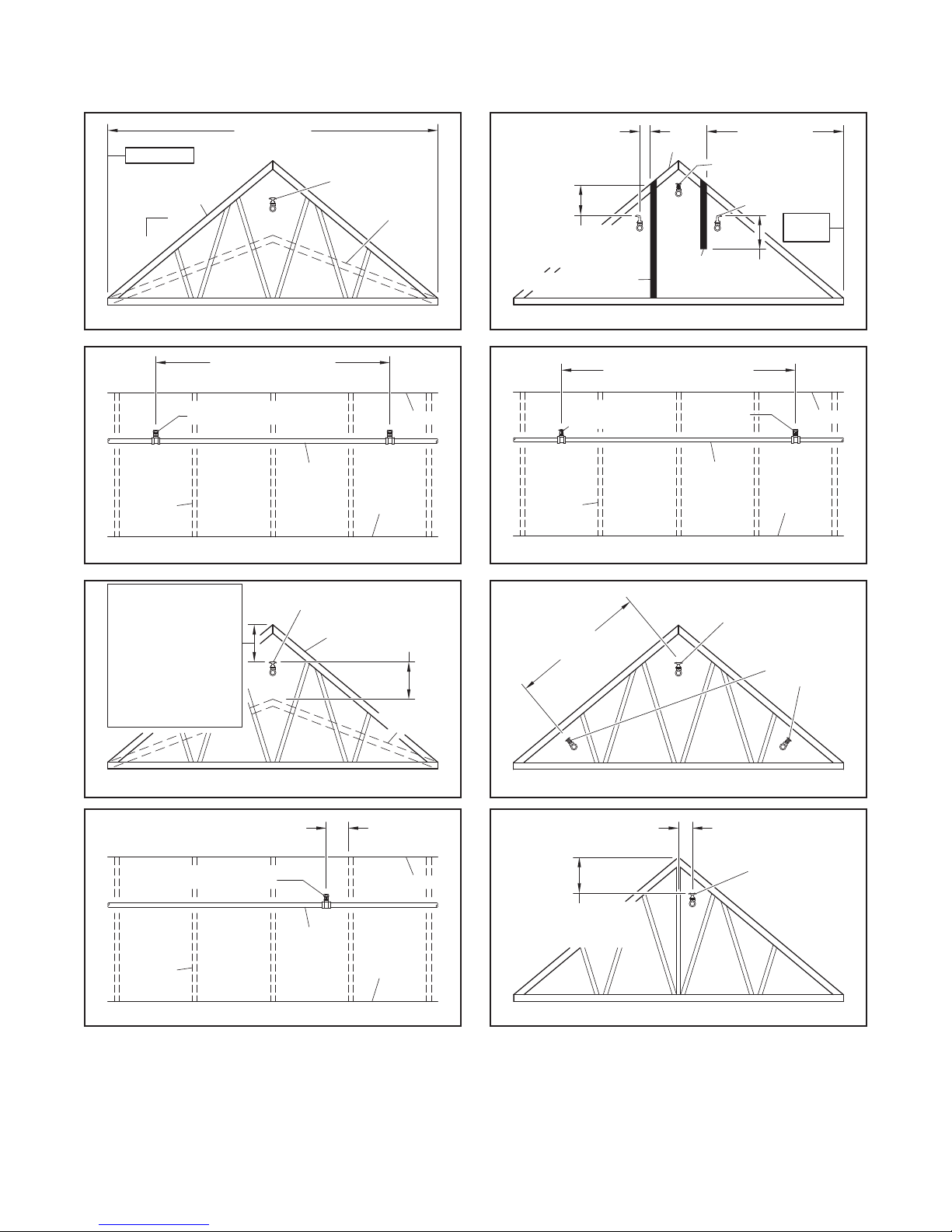
Page 10
TFP610
ROOF SPAN
6" (152,4 mm) MAX.
ROOF SPAN
6'-0" (1,83 m) MAXIMUM
RIDGE
7'-0" (2,1 m) MIN. FOR AP SPRINKLERS
RIDGE
22" (558,8 mm) MAX.
BB, SD or HIP ATTIC
BB, SD or HIP
6" (152,4 mm)
6" (152,4 mm)
Page 10 of 28
SEE FIG. 11
12
4-12
TRUSS
STANDARD
TRUSS
BB or SD ATTIC
SPRINKLERS
(COVERAGE)
BACK TO BACK
SPRINKLER
SCISSOR
TRUSS
4" (101,6 mm) MIN.
FROM WALL
22" (558,8 mm) MAX.
16" (406,4 mm) MIN.
BOTTOM OF SHEATHING
FULL WALL TO DECK
FIGURE 1 FIGURE 2
4'-0" (1,22 m) MINIMUM
BRANCH
LINE
CEILING
TRUSS CEILING
6'-0" (1,8 m) MINIMUM FOR
STANDARD SPRAY SPRINKLERS
AP or STANDARD
SPRAY SPRINKLER
FIGURE 3 FIGURE 4
DECK
DRAFT
CURTAIN
TO DECK
(COVERAGE)
AP or STANDARD
SPRAY SPRINKLER
SINGLE DIRECTIONAL
SPRINKLERS
8" MIN.
(203,2 mm)
ATTIC
SPRINKLER
BRANCH
LINE
SEE
FIG. 11
16" (406,4 mm) MIN.
-or-
FOR A ROOF PITCH
LESS THAN 4:12 (33%),
12" (304,8 mm) MAXIMUM
BELOW PEAK AND 1"
(25,4 mm) MINIMUM
BELOW BOTTOM OF
TOP CHORD OR
RAFTER
BB, SD or HIP
SPRINKLER
TRUSS
SPRINKLER
FIGURE 5
MINIMUM
BRANCH
STANDARD
LINE
TRUSS
18" MIN.
(457,2 mm)
SCISSOR
TRUSS
RIDGE
CEILING
26'-0" (7,92 m)
MINIMUM
MAXIMUM
22" (558,8 mm) MAX.
16" (406,4 mm) MIN.
BOTTOM OF SHEATHING
FIGURE 6
FIGURE 7 FIGURE 8
ATTIC
SPRINKLER
BB or HIP
SPRINKLER
AP or
STANDARD
SPRAY
SPRINKLERS
ATTIC
Page 11

TFP610
PROTECTION
12" MIN.
12" MIN.
SPRINKLER
& FITTINGS
SPRINKLER
& FITTINGS
NON-COMBUSTIBLE INSULATION
OPTION A
CEILING
ATTIC
PROTECTED
(152,4 mm)
NON-COMBUSTIBLE INSULATION
FOR FIRE PROTECTION OF CPVC PIPE,
ATTIC
CEILING
NOT EQUAL ANGLE "B"
SINGLE DIRECTIONAL
AP or STANDARD
INSULATION
OR TOP CHORD
Page 11 of 28
CEILING
(304,8 mm)
NON-COMBUSTIBLE
INSULATION FOR FIRE
PROTECTION OF CPVC
ATTIC
SPRINKLER
PROTECTED
SPACE
CEILING
JOIST
CPVC PIPE
(304,8 mm)
FIGURE 9A
FOR FIRE PROTECTION OF CPVC PIPE,
NOT FREEZE PROTECTION
OPTION B
6" MIN.
(152,4 mm)
CPVC PIPE
CEILING
JOIST
FIGURE 9B
6" MIN.
(152,4 mm)
PIPE, NOT FREEZE
SPRINKLER
SPACE
SPRINKLERS AS
APPROPRIATE FOR
RESPECTIVE SLOPE
DRAFT CURTAIN
(SHOWN)
OR FULL WALL
TO ROOF DECK
A B
WHEN ANGLE "A" DOES
8" MIN.
(203,2 mm)
FIGURE 10
PERMITTED USE OF ATTIC SPRINKLERS
FOR MISMATCHED SLOPES
SPRAY SPRINKLER
COVERAGE ON SLOPE
BB, SD or HIP
COVERAGE ON
HORIZONTAL
NOT FREEZE PROTECTION
CEILING
CEILING
ELEVATION
CHANGE
NON-COMBUSTIBLE INSULATION
FOR THE PROTECTION OF CPVC PIPE
FIGURE 9C
FIGURE 9
SPRINKLER
PROTECTED
SPACE
VERTICAL
RISE
CPVC PIPE
& FITTINGS
6" MIN.
JOIST
MAXIMUM
2" (50 mm) VENT
PERMITTED
TOP OF
INSULATION
NON-COMBUSTIBLE
CEILING
JOIST
ROOF JOIST
OR TOP CHORD
AP or STANDARD
SPRAY SPRINKLER
COVERAGE ON SLOPE
BB, SD or HIP
COVERAGE ON
HORIZONTAL
ROOF JOIST
FIGURE 11
COVERAGE STARTING POINT AT EAVE
Page 12
TFP610
7'-6" (2,3 m) MAX. HORIZONTAL
ON HIP SLOPE
HIP SLOPE
28'-0" (8,5 m)
HORIZONTAL
SPRINKLERS
6'-0" (1,8 m) MAX.6'-0" (1,8 m) MAX.
TRUSSES IN HIP SLOPE AREA
PARALLEL TO OUTSIDE WALL
6'-0" (1,8 m) MAX.
HIP RIDGES
Page 12 of 28
SEE FIG. 11
HIP ROOF INSTALLATION
FIGURE 12
WITH RAFTERS FRAMED
PERPENDICULAR TO
OUTSIDE WALL
(SHOWN WITH HIP
SPRINKLERS PROTECTING
HIP SLOPE AND ADJACENT
AREAS TO HIP SLOPE )
FIGURE 13A
HIP ROOF INSTALLATION
WITH TRUSSES FRAMED
PARALLEL TO OUTSIDE WALL
(SHOWN WITH STANDARD
SPRAY OR AP SPRINKLERS
IN HIP SLOPE)
WHERE AN AREA
(SHOWN NON-SHADED)
IS PROTECTED
WITH AP SPRINKLERS,
CPVC MAY BE
USED FOR CEILING
PROTECTION BELOW
(SEE PAGE 6)
HIP SPRINKLERS
PROTECT AREA ON
BOTH SIDES OF
RAFTERS IN HIP SLOPE
AREA PERPENDICULAR
TO OUTSIDE WALL
MAXIMUM
SEE FIG. 11
STANDARD SPRAY
SPRINKLERS INSTALLED
PER NFPA 13 IN HIP SLOPE
AREA WHEN TRUSSES
ARE FRAMED PARALLEL
TO OUTSIDE WALL
TRUSSES IN HIP SLOPE AREA
PARALLEL TO OUTSIDE WALL
MAXIMUM
40'-0" (12,2 m)
HORIZONTAL
ROOF SPAN
(COVERAGE)
OUTSIDE WALL
SINGLE
DIRECTIONAL
SPRINKLERS
HIP RIDGES
HIP RIDGE
OUTSIDE
WALL
HIP
RIDGES
6'-0" (1,8 m) MAX.
HIP
SLOPE
3'-0" (0,9 m) MIN.
HIP
SLOPE
3'-0" (0,9 m)
MAX. ON
TO BACK
RIDGE LINE
BACK
TO BACK
SPRINKLERS
ROOF
SLOPE
RIDGE LINE
3'-0" (0,9 m)
MAX. ON
HIP SLOPE
BACK
ROOF
SLOPE
HIP ROOF INSTALLATION
WITH TRUSSES FRAMED
PARALLEL TO OUTSIDE WALL
(SHOWN WITH STANDARD
SPRAY OR AP SPRINKLERS IN
HIP SLOPE AND ADJACENT
AREAS TO HIP SLOPE )
FIGURE 13B
3'-0" (0,9 m)
MAX. ON
HIP SLOPE
STANDARD SPRAY
SPRINKLERS INSTALLED
PER NFPA 13 IN HIP SLOPE
AREA WHEN TRUSSES
ARE FRAMED PARALLEL
TO OUTSIDE WALL
OUTSIDE WALL
WHERE AN AREA
(SHOWN NON-SHADED)
IS PROTECTED
WITH AP SPRINKLERS,
CPVC MAY BE
USED FOR CEILING
PROTECTION BELOW
(SEE PAGE 6)
CPVC PIPE MAY BE USED IN SHADED AREA ONLY
FOR CEILING PROTECTION BELOW (SEE PAGE 6)
BACK
TO BACK
SPRINKLERS
HIP
SLOPE
CPVC PIPE MAY BE USED IN SHADED AREA ONLY
FOR CEILING PROTECTION BELOW (SEE PAGE 6)
ROOF
SLOPE
RIDGE LINE
Page 13
TFP610
6'-0" MAX.
SPRINKLERS
10'-0" (3,0 m)
(TABLE A)
BACK
AT THE EAVES
Page 13 of 28
Attic Spaces Greater Than 60 ft (18,3m) up to 80 ft (24,4m) Wide, (refer to Figures 14 and 15).
Only 8.0 K, BB Sprinklers in conjunction with AP Sprinklers or Standard Spray Sprinklers can be used to protect attics up
to 80 ft (24,4 m) wide.
NOTES:
•
Attics over 80 ft (24,4 m) wide must use Standard Spray Sprinklers throughout because Attic Sprinklers have not been
tested in this scenario.
•
For single ridge construction (refer to Figure 14A and 14B), use 8.0K, BB Sprinklers to protect the center portion. AP
Sprinklers (refer to Figure 14A) or Standard Spray Sprinklers (refer to Figure 14B) are then used to protect up to 10 ft
(3,1 m) of width at the eaves beyond the maximum allowable 60 ft (18,3 m) span of the 8.0K, BB Sprinklers.
•
For hip roof construction (refer to Figure 15), use 8.0K, BB Sprinklers in the center portion and HIP Sprinklers can be
located down the entire hip. AP Sprinklers or Standard Spray Sprinklers are then used to protect up to 10 ft (3,1 m) of
width at the eaves beyond the maximum allowable 60 ft (18,3 m) span of the 8.0K, BB Sprinklers, and the maximum
allowable horizontal coverage of the HIP Sprinklers.
SEE FIG. 11
10'-0" MAX.
(3,05 m)
AP
SPRINKLER
COVERAGE
BB SPAN
(TABLE A)
6'-0"
(1,83 m)
MAX.
6'-0" MAX.
(1,83 m)
4'-0" MIN.
(1,22 m)
FIGURE 14A
SPRINKLERS
PERIMETER
PROTECTION
BB ATTIC
SPRINKLER
10'-0"
(3,0 m)
HIP
RIDGES
AP
AREA
AP
SPRINKLERS
SPACED
7'-0" (1,8 m)
TO
10'-0" (3,0 m)
ON CENTER
HIP
SLOPE
HIP
SPRINKLERS
(1,83 m)
4'-0" MIN.
(1,22 m)
TO BACK
SPRINKLERS
SEE FIG. 11
10'-0" MAX.
(3,05 m)
AP SPRINKLER
COVERAGE
FIGURE 14B
10'-0"
(3,0 m)
RIDGE
LINE
ROOF
SLOPE
BB
SPAN
SD SPAN
(TABLE A)
6'-0"
(1,83 m)
MAX.
SD ATTIC
SPRINKLER
AP
SPACED
7'-0" (1,8 m)
TO
ON CENTER
CPVC PIPE MAY
BE USED IN SHADED
AREA FOR CEILING
PROTECTION BELOW
(SEE PAGE 6)
FIGURE 15
10'-0"
(3,0 m)
7'-0" to 10'-0"
(2,1 m to 3,0 m)
ON CENTER FOR
AP SPRINKLERS
Page 14

TFP610
BB ATTIC
BB ATTIC
BB ATTIC
LESS THAN
BB ATTIC
Page 14 of 28
NO
ADDITIONAL
SPRINKLER
REQUIRED
3-1/2" MIN.
(88,9 mm)
AIR SPACE
SPRINKLER
36" MIN.
(914,4 mm)
6" MAX.
(152,4 mm)
GREATER
THAN 6"
(152,4 mm)
ANY
DISTANCE
SPRINKLER
ADDITIONAL AP
OR STANDARD SPRAY
SPRINKLER REQUIRED
(LOCATE PER FIGURE
14A OR 14B)
FIGURE 16A FIGURE 16B
There can be a maximum of a 6 in. (152,4 mm) high Horizontal Obstruction as long as it is 36 in. (914,4 mm), measured
vertically, below the Attic Sprinkler. If the obstruction is closer or larger, there must be a sprinkler on the other side of the
obstruction. Refer to Figures 16A and 16B. This criteria does not limit the top chord of the trusses or the depth of the rafter, but does limit the obstructions that run across the trusses or rafters.
6" (152,4 mm)
NO
ADDITIONAL
SPRINKLER
REQUIRED
ADDITIONAL AP
OR STANDARD SPRAY
SPRINKLER(S)
REQUIRED (LOCATE
PER FIGURE
14A OR 14B)
MINIMUM
6" (152,4 mm)
SPRINKLER
4'-0" (1,2 m)
MAXIMUM
FIGURE 16C
SPRINKLER
36" (914,4 mm)
MINIMUM
36" (914,4 mm)
MINIMUM
Dimension A
Maximum
Horizontal
Dimension of
Obstruction
All Vertical Obstructions
1/2"-1" (12,7 mm-25,4 mm)
1"-4" (25,4 mm-101,6 mm)
4"-8" (101,4 mm-203,2 mm)
8"-10" (203,2 mm-254,0 mm)
10"-20" (254,0 mm-508,0 mm)
20"-30" (508,0 mm-762,0 mm)
30"-40" (762,0 mm-1016,0 mm)
40"-48" (1016,0 mm-1219,2 mm)
> 48" (1219,2 mm)
Distance B
Minimum
Horizontal
Distance to
Obstruction
< 6" (152,4 mm)
6" (152,4 mm)
12" (304,8 mm)
24" (609,6 mm)
5'-0" (1,52 m)
10'-0" (3,05 m)
15'-0" (4,57 m)
20'-0" (6,10 m)
25'-0" (7,62 m)
Any Distance
Additional
Sprinkler
Required
Beyond
Obstruction
YES
NO
NO
NO
NO
NO
NO
NO
NO
YES
GREATER THAN
4'-0" (1,2 m)
FIGURE 16D
If the Horizontal Obstruction is below the sprinkler, there
must be 6 in. (152,4 mm) clearance over the top of the
obstruction, and the obstruction must be 4 ft (1,2 m) or
less in width to allow water to pass both over and under
the obstruction. The clearance is measured perpendicular to and from the bottom of the rafter. If there is not
6 in. must be located on the other side of the obstruction. If the obstruction is greater than 4 ft (1,2 m) in width,
a sprinkler must be added below the obstruction. Refer
to Figures 16C and 16D, where the maximum spacing for
AP Sprinklers is 12 ft (3,7 m) and Standard Spray Sprinklers is 15 ft (4,6 m).
OBSTRUCTIONS TO WATER DISTRIBUTION — BB, SD AND HIP
DIMENSION B
PER TABLE
For Vertical Obstructions, the maximum dimension of the
obstruction is its width and the horizontal distance away
from the obstruction is measured horizontally.
FIGURE 16 (1 OF 2 )
ADDITIONAL AP
OR STANDARD SPRAY
SPRINKLER REQUIRED
(LOCATE PER FIGURE
FIGURE 16E
DIMENSION A
PER TABLE
14A OR 14B)
Page 15

TFP610
6" (152,4 mm) TYP.
DIRECTIONAL SPRINKLERS
SPRINKLERS
BB ATTIC
36" (914,4 mm)
22" (558,8 mm) MAX.
DIRECTIONAL
SPRINKLER
OR FULL WALL
DIRECTIONAL
SPRINKLER
(304,8 mm)
"V"
Page 15 of 28
AREA OUTSIDE OF MECHANICAL SPACE
FIGURE 16F
OR SIMILAR COMPARTMENTAL SPACE
When a BB Sprinkler is 36 in. (914,4 mm) or greater above
the space, and 36 in. (914,4 mm) or greater clearance
above the space is present, additional sprinklers are not
needed.
When a BB Sprinkler is 36 in. (914,4 mm) or greater above
the space, and a 12 to 36 in. (304,8 to 914,4 mm) clearance above the space is present, Intermediate Level Standard Sprinklers are to be installed to protect the obstructed
area.
Otherwise, the area beyond the mechanical space is to be
protected as shown by installing Standard Spray Sprinklers
as necessary or by constructing a shear wall and installing
SD Sprinklers.
Note: In all cases, the mechanical space or similar compartmented
space is to be sprinklered per its respective hazard rating and separated from the light hazard attic space by construction that has a
fire resistance rating based on the water supply duration required
for the hazard rating within the mechanical space or similar compartmented space.
NO
ADDITIONAL
SPRINKLERS
REQUIRED
36" (914,4 mm)
OR GREATER
SPRINKLER
OR GREATER
FIGURE 16G
PIGGYBACK TRUSSES
When a BB Sprinkler can be installed below or between
stiffeners and maintain the 16 to 22 in. (404,4 to 558,8
mm) distance to the peak, as well as the “V” and “H”
clearance to the stiffeners, additional sprinklers are not
required.
When the stiffeners are located a minimum of 12 in.
(304,8 mm) below the BB Sprinkler, the stiffeners are
7-1/2 in. (190,5 mm) maximum in width, the openings are
12 in. (304,8 mm) minimum, and there is 70% minimum
open area, additional sprinklers are not required.
Otherwise, additional sprinklers are required as shown.
H
BB2
V + 10"
16" (406,4 mm) MIN.
BB3
0"
0"
V + 8"V > 0"
BOTTOM
PLANE OF
STIFFENERS
"V"
"H"
STIFFENERS
V
BB1
0"
0"
V + 15"
STANDARD
SPRAY SPRINKLER
12" (304,8 mm) TO
36" (914,4 mm)
INTERMEDIATE
LEVEL
STANDARD SPRAY
SPRINKLER
STANDARD
SPRAY SPRINKLER
SPRINKLER
LESS THAN
12" (304,8 mm)
PROTECT WITH
STANDARD SPRAY
MECHANICAL
SPACE
4" (101,6 mm) TO
6" (152,4 mm) TYP.
MECHANICAL
SPACE
BB ATTIC
MECHANICAL SPACE
-OR-
36" (914,4 mm)
OR GREATER
BB ATTIC
SPRINKLER
4" (101,6 mm) TO
STANDARD
SPRAY SPRINKLER
ADD SHEAR WALL AND
PROTECT WITH SINGLE
TOP OF
DEFLECTOR
STIFFENERS
3-1/2" MIN.
(88,9 mm)
AIR SPACE
7-1/2" MAX.
(190,5 mm)
INTERMEDIATE
LEVEL
STANDARD
SPRINKLER
SINGLE
BB ATTIC
SPRINKLER
BB ATTIC
SPRINKLER OR
STANDARD SPRAY
SPRINKLER
INSTALL
DRAFT CURTAIN
BB ATTIC
SPRINKLER
70% MINIMUM
OPEN AREA
12" MIN.
(304,8 mm)
LESS THAN
70% OPEN AREA,
OPENINGS LESS THAN
12" (304,8 mm) WIDE,
OR STIFFENERS
GREATER THAN
7-1/2" (190,5 mm)
WIDE
12" MIN.
SINGLE
(Obstructions to Water Distribution for Attic Sprinklers Differ from Standard Sprinklers as Shown)
FIGURE 16 (2 OF 2) OBSTRUCTIONS TO WATER DISTRIBUTION — BB, SD, AND HIP
Page 16

TFP610
OPTION A
OPTION B
OPTION B
OPTION A
OBSTRUCTION
OBSTRUCTION
Page 16 of 28
FIGURE 17A
EXPOSED CPVC
WITH AP SPRINKLERS
AND
BRANCHLINE OVER
JOISTS
FIGURE 17B
EXPOSED CPVC
WITH AP SPRINKLERS
AND
BRANCHLINE WITHIN
JOISTS
3'-0" MAX.
(0,9 m)
JOIST
12" MIN.
(304,8 mm)
NON-COMBUSTIBLE
INSULATION FOR FIRE
PROTECTION OF CPVC
PIPE, NOT FREEZE
PROTECTION
3'-0" MAX.
(0,9 m)
6" MIN.
(152,4 mm)
CEILING
NON-COMBUSTIBLE
INSULATION FOR FIRE
PROTECTION OF CPVC
PIPE, NOT FREEZE
PROTECTION
AP
SPRINKLER
AP
SPRIG
6" MIN.
(152,4 mm)
12" MIN.
(304,8 mm)
CEILING
AP
SPRINKLER
AP
SPRIG
JOIST
10'-0" MAX.
(3,0 m)
JOIST
12" MIN.
(304,8 mm)
NON-COMBUSTIBLE
INSULATION FOR FIRE
PROTECTION OF CPVC
PIPE, NOT FREEZE
PROTECTION
10'-0" MAX.
(3,0 m)
6" MIN.
(152,4 mm)
CEILING
NON-COMBUSTIBLE
INSULATION FOR FIRE
PROTECTION OF CPVC
PIPE, NOT FREEZE
PROTECTION
AP
SPRINKLER
AP
SPRIG
6" MIN.
(152,4 mm)
12" MIN.
(304,8 mm)
CEILING
AP
SPRINKLER
AP
SPRIG
JOIST
FIGURE 18
OBSTRUCTIONS TO WATER
DISTRIBUTION FOR
MODEL AP SPRINKLERS
A
C
D
ELEVATION VIEW PLAN VIEW
A
B
AP
SPRINKLER
AP
SPRINKLER
OBSTRUCTION
A ≥ 3C or 3D
A ≤ 24" (609,6 mm)
(Use dimension C or D,
whichever is greater)
≤6"
(≤152,4 mm)
>6" to 9"
(>152,4 mm to 228,6 mm)
>9" to 12"
(>228,6 mm to 304,8 mm)
>12" to 15"
(>304,8 mm to 381,0 mm)
>15" to 18"
(>381,0 mm to 457,2 mm)
>18" to 24"
(>457,2 mm to 609,6 mm)
>24" to 30"
(>609,6 mm to 762,0 mm)
>30"
(>762,0 mm)
C
Horizontal
Distance
(A)
D
AP
SPRINKLER
A
Minimum
Vertical Distance
Below Deector
(B)
3"
(76,2 mm)
4"
(101,6 mm)
6"
(88,9 mm)
8"
(203,2 mm)
9-1/2"
(241,3 mm)
12-1/2"
(317,5 mm)
15-1/2"
(393,7 mm)
18"
(457,2 mm)
Page 17

TFP610
ARMOVER
MODEL AP
OR STANDARD
SPRAY
Page 17 of 28
A = 6" (150 mm) MAX.
A
B
A
B = 12" (300 mm) MAX.
A
ANGLE SPRIG
ARMOVER SPRIG
BRANCHLINE
VERTICAL SPRIG
VERTICAL RISER VERTICAL RISER
B
BRANCHLINE
DIRECT MOUNT
FIGURE 19
HYDRAULIC CALCULATIONS
Attic sprinklers must be calculated in conformance with these guidelines. In all cases, the design area shall include the
most hydraulically demanding sprinklers. More than one set of calculations may be required to prove different situations.
For individual areas requiring more than four AP Sprinklers, the maximum area of attic protected by AP Sprinklers is limited
to 3000 ft2 (279 m2) in any single area. Areas must be separated by a minimum of 15 ft (4,6 m) by an area protected by BB,
SD,or HIP Sprinklers, in order to be considered separate areas.
The hydraulic calculations have been divided into three parts as follows:
• FIGURE 20-A: “Attics Protected Entirely By BB, SD, and HIP Attic Sprinklers”.
20-A-1 (Page 18) BB Sprinklers
20-A-2 (Page 18) BB and HIP Sprinklers
20-A-3 (Page 19) BB and SD Sprinklers
20-A-4 ( Page 19) SD Sprinklers
20-A-5 (Page 19) SD and HIP Sprinklers
20-A-6 (Page 19) HIP Sprinklers
• FIGURE 20-B: “Attics Protected With A Mixture Of BB. SD, and HIP Attic Sprinklers And AP Sprinklers”.
20-B-1 (Page 20) SD Sprinklers and AP Sprinklers At The Ridge
20-B-2 (Page 20) BB Sprinklers and AP Sprinklers At The Eaves or Beyond An Obstruction
20-B-3 (Page 21) BB Sprinklers and AP Sprinklers At The Hip
20-B-4 (Page 21) BB Sprinklers, SD Sprinklers, HIP Sprinklers, and AP Sprinklers At The Hip
20-B-5 (Page 22) BB, SD, or HIP Sprinklers and AP Sprinklers in a Dormer, at a Cross, or at an Ell
20-B-6 (Page 22) BB,SD, or HIP Sprinklers and AP Sprinklers Separated By Compartmentalization
• FIGURE 20-C: “Attics Protected With A Mixture Of BB. SD, and HIP Attic Sprinklers And Standard Spray
Sprinklers”.
20-C-1 (Page 23) SD Sprinklers and Standard Spray Sprinklers At The Ridge
20-C-2 (Page 23) BB Sprinklers and Standard Spray Sprinklers At The Eaves or Beyond An Obstruction
20-C-3 (Page 24) BB Sprinklers and Standard Spray Sprinklers At The Hip
20-C-4 (Page 25) BB Sprinklers, SD Sprinklers, HIP Sprinklers, and Standard Spray Sprinklers At The Hip
20-C-5 (Page 26) BB, SD, or HIP Sprinklers and Standard Spray Sprinklers in a Dormer, at a Cross, or at an Ell
20-C-6 (Page 26) BB, SD, or HIP Sprinklers and Standard Sprinklers Separated By Compartmentalization
MODEL BB
BACK TO BACK
MODEL SD
SINGLE DIRECTIONAL
FIGURE 20
HYDRAULIC CALCULATIONS
MODEL HIP
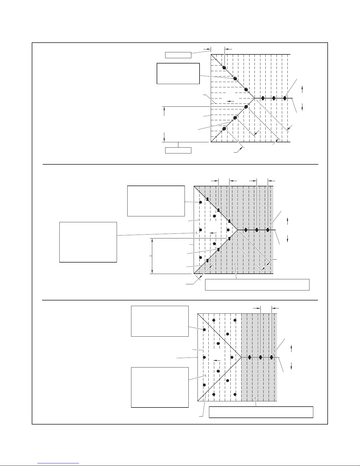
Page 18

TFP610
DRY SYSTEM SHOWN
DRY SYSTEM SHOWN
Page 18 of 28
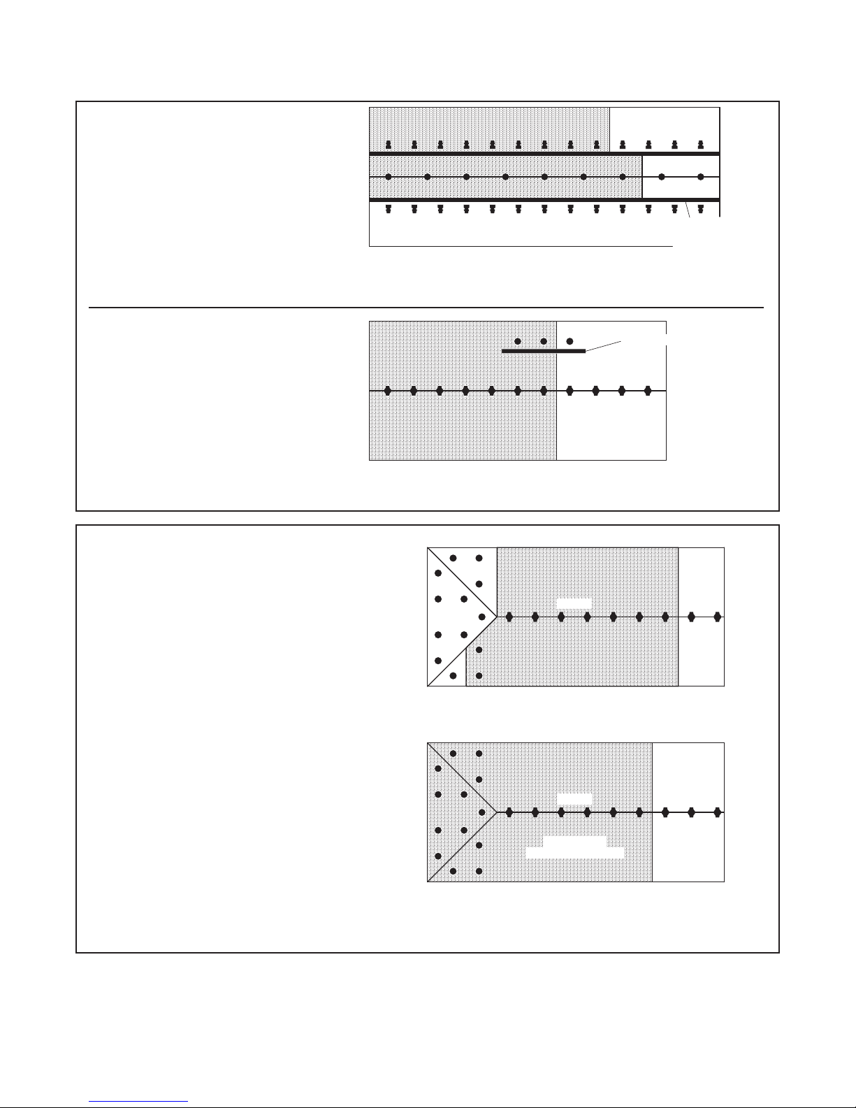
FIGURE 20-A-1. BB SPRINKLERS
•
Wet Systems: Calculate the most
demanding ve sprinklers.
•
Dry Systems: Calculate the most
demanding seven sprinklers. See
the adjacent gure.
RIDGE
HIP
RIDGE
FIGURE 20-A-2. BB AND HIP
SPRINKLERS
•
Wet Systems: Calculate the most
demanding ve sprinklers.
•
Dry Systems: Calculate the most
demanding seven sprinklers. Then
calculate the most demanding
contiguous nine sprinklers with a
maximum of seven to be BB Sprinklers. See the adjacent gures. Use
the most demanding calculation.
DRY SYSTEM SHOWN
HIPVALLEY
RIDGE
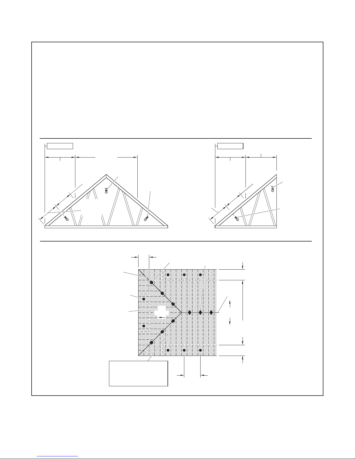
Page 19

TFP610
DRY SYSTEM SHOWN
DRY SYSTEM SHOWN
DRAFT CURTAIN
DRY SYSTEM SHOWN
DRAFT CURTAIN
WET SYSTEM SHOWN
Page 19 of 28
FIGURE 20-A-3. BB AND SD
SPRINKLERS
•
Wet Systems: Calculate the most
demanding ve BB Sprinklers
plus two SD Sprinklers.
•
Dry Systems: Calculate the most
demanding seven BB Sprinklers
plus up to two SD Sprinklers. See
the adjacent gure.
FIGURE 20-A-4. SD SPRIN-
KLERS
•
Wet Systems: Calculate the most
demanding ve SD Sprinklers.
•
Dry Systems: Calculate the most
demanding nine SD Sprinklers.
See the adjacent gure.
FIGURE 20-A-5. SD AND HIP
SPRINKLERS
•
Wet Systems: Calculate the most
demanding ve sprinklers.
•
Dry Systems: Calculate the most
demanding nine sprinklers with
a maximum of seven to be SD
Sprinklers. See the adjacent
gure.
OBSTRUCTION
RIDGE
RIDGE
WALL OR
AT RIDGE
HIP
RIDGE
WALL OR
AT RIDGE
FIGURE 20-A-6. HIP SPRIN-
KLERS
•
Wet Systems: Calculate the most
demanding ve sprinklers. See
the adjacent gure.
•
Dry Systems: Calculate the most
demanding nine sprinklers.
HIP
HIP
HIP
HIP
Page 20

TFP610
DRY SYSTEM SHOWN
WALLS OR
CURTAINS
OBSTRUCTION
DRY SYSTEM SHOWN
Page 20 of 28
FIGURE 20-B-1. SD SPRINKLERS
AND AP SPRINKLERS AT THE
•
Wet Systems: Calculate the most
demanding ve sprinklers of one
type. Use the most demanding
calculation.
•
Dry Systems: Calculate the most
demanding nine SD Sprinklers,
and then calculate the most
demanding seven AP Sprinklers.
Use the most demanding calculation. See the adjacent gure.
RIDGE
RIDGE
DRAFT
RIDGE
FIGURE 20-B-2. BB OR SD
SPRINKLERS AND AP SPRIN-
KLERS AT THE EAVES OR BE-
YOND AN OBSTRUCTION
•
Wet Systems: Calculate the
most demanding ve BB or SD
Sprinklers plus up to two most
demanding AP Sprinklers.
•
Dry Systems: Calculate the most
demanding seven BB or SD
Sprinklers plus up to two most
demanding AP Sprinklers. See the
adjacent gures.
DRY SYSTEM SHOWN
RIDGE
DRY SYSTEM SHOWN
Page 21

TFP610
AREA 2
AREA 1
AREA 3
15'-0" (4,6 m)
SPACING WHEN
WALL OR
CURTAIN
15'-0" (4,6 m)
SPRINKLERS
SPRINKLERS
Page 21 of 28
BB SPRINKLERS AND AP SPRIN-
FIGURE 20-B-3.
KLERS AT THE HIP
Where the total number of AP Sprinklers
at the hip is greater than four:
•
Wet Systems: Calculate the most
demanding ve BB Sprinklers
plus the two most demanding
AP Sprinklers. Then calculate
the most demanding area up to
150 0 ft2 (137 m2) having AP Sprinklers, for example, Area 2 in the
adjacent upper gure. Use the most
demanding calculation.
•
Dry Systems: Calculate the most
demanding seven BB Sprinklers
plus the two most demanding
AP Sprinklers. Then calculate
the most demanding area up to
1950 f t2 (181 m2) having AP Sprinklers, for example, Area 2 in the
adjacent upper gure. Use the most
demanding calculation.
FIGURE 20-B-4. BB SPRINKLERS,
SD SPRINKLERS, HIP SPRIN-
KLERS, AND AP SPRINKLERS AT
THE HIP
Where the total number of AP Sprinklers
at the hip is four or less:
• Wet Systems: Calculate the most demanding ve BB, SD, or HIP Sprinklers plus up to two most demanding
AP Sprinklers.
•
Dry Systems: Calculate the most
demanding nine BB, SD, or HIP
Sprinklers plus up to two most
demanding AP Sprinklers (Of the
nine BB, SD, or HIP Sprinklers,
calculate up to a maximum of seven
BB Sprinklers, see adjacent upper
gure).
Where the total number of AP Sprinklers
at the hip is greater than four:
•
Wet Systems: Calculate up to the
most demanding ve BB, SD, or
HIP Sprinklers plus the two most
demanding AP Sprinklers. Then
calculate the most demanding area
up to 1500 ft2 (137 m2) having AP
Sprinklers, for example, Area 2. Use
the most demanding calculation.
•
Dry Systems: Calculate up to the
most demanding nine BB, SD, or
HIP Sprinklers, plus the two most
demanding AP Sprinklers, and then
calculate the most demanding area
up to 1950 ft2 (181 m2) having AP
Sprinklers, for example, Area 2. Use
the most demanding calculation.
STAGGERED
MORE THAN
ONE ROW
DRAFT
AREA 2
WITH AP
WITH AP
SPRINKLERS
WITH BB
SPRINKLERS
MINIMUM
SEPARATION
RIDGE
DRY SYSTEM SHOWN
AREA 1
WITH BB & SD
SPRINKLERS
MINIMUM
SEPARATION
WITH AP
SPRINKLERS
AREA 3
WITH AP
Page 22

TFP610
SPRINKLERS
SPRINKLERS
Page 22 of 28
FIGURE 20-B-5. BB, SD, OR HIP
SPRINKLERS AND AP SPRIN-
KLERS IN A DORMER, AT A
CROSS, AT A HIP, OR AT AN ELL
Where the quantity of AP Sprinklers
in each dormer, cross, or ell is four or
less (see the adjacent figure) and all
of the dormers, crosses and ells meet
the maximum four AP Sprinkler criteria, calculate the BB, SD, or HIP Sprinkler demand as described in Part A-1
through A-6 or Part B-1 through B-4,
plus up to two of the most demanding
AP Sprinklers in the dormer, cross, or
ell that is adjacent to the BB, SD, or HIP
Sprinklers that are being included in the
demand calculation.
Where the quantity of AP Sprinklers in
any dormer, cross, or ell is greater than
four, refer to Figure B- 3.
AP
SPRINKLERS
(4 OR LESS)
AP
SPRINKLERS
(4 OR LESS)
FIGURE 20-B-6. BB,SD, OR HIP
SPRINKLERS AND AP SPRIN-
KLERS SEPARATED BY
COMPARTMENTALIZATION
•
Wet Systems: Calculate the BB,
SD, or HIP Sprinkler demand as
described in Part A-1 through A-6 or
Part B-1 through B-4. Then calculate
the most demanding area up to
150 0 ft2 (137 m2) having AP Sprinklers. Use the most demanding
calculation. See the adjacent gure.
•
Dry Systems: Calculate the BB,
SD, or HIP Sprinkler demand as
described in Part A-1 through A-6 or
Part B-1 through B-4. Then calculate
the most demanding area up to
1950 f t2 (181 m2) having AP Sprinklers. Use the most demanding
calculation. See the adjacent gure.
AP
(4 OR LESS)
WALL
RIDGE
RIDGE
DORMER
BUILT ON TOP
OF ROOF OR
SHEATHING
AP
(4 OR LESS)
Page 23
DRY SYSTEM SHOWN
WALLS OR
CURTAINS
DRY SYSTEM SHOWN
OBSTRUCTION
FIGURE 20-C-1. SD SPRINKLERS
FIRST CALCULATION
NOTE:
Dry Pipe = 1500 SQ. FT. (NFPA Light Hazard) x 1.3 x 1.3 = 2535 SQ. FT.
AND STANDARD SPRAY SPRIN-
KLERS AT THE RIDGE
•
Wet Systems: Calculate the most
demanding ve sprinklers of one
type. Use the most demanding
calculation.
•
Dry Systems: Calculate the most
demanding nine SD Sprinklers. Then
calculate the most demanding seven
Standard Spray Sprinklers. Use the
most demanding calculation. See
the adjacent gures.
FIGURE 20-C-2. BB SPRINKLERS
AND STANDARD SPRAY SPRIN-
KLERS BEYOND AN OBSTRUCTION
•
Wet Systems: Calculate the most
demanding ve BB Sprinklers plus
up to two most demanding Standard
Spray Sprinklers.
•
Dry Systems: Calculate the most
demanding seven BB Sprinklers plus
up to two most demanding Standard
Spray Sprinklers. See the adjacent
gures.
TFP610
Page 23 of 28
RIDGE
DRAFT
RIDGE
FIGURE 20-C-3. BB SPRINKLERS
AND STANDARD SPRAY SPRIN-
KLERS AT THE HIP
Where the total number of standard
spray sprinklers at the hip is greater
than four:
•
Wet Systems: Calculate the most
demanding ve BB Sprinklers plus
up to two most demanding Standard
Spray Sprinklers. Then calculate the
most demanding remote design
area, including all sprinkler types, as
per NFPA 13. That is, area reduction
for quick response and 30%
increase for sloped ceilings. Use the
most demanding calculation.
•
Dry Systems: Calculate the most
demanding seven BB Sprinklers
plus up to two most demanding
Stand Spray Sprinklers. Then
calculate the most demanding
design area, including all sprinkler
types, as per NFPA 13. That is, 30%
increase for sloped ceilings and 30%
increase for dry systems. Include all
sprinkler types within this area. See
the adjacent gure. Use the most
demanding calculation.
RIDGE
DRY SYSTEM SHOWN
SECOND CALCULATION
RIDGE
2535 SQ. FT.
(235,5 SQ. METERS)
DRY SYSTEM SHOWN
Page 24

TFP610
NOTE:
Dry Pipe = 1500 SQ. FT. (NFPA Light Hazard) x 1.3 x 1.3 = 2535 SQ. FT.
Page 24 of 28
FIGURE 20-C-4. BB SPRINKLERS,
SD SPRINKLERS, HIP SPRIN-
KLERS, AND STANDARD SPRAY
SPRINKLERS
AT THE HIP
Where the total number of Standard
Spray Sprinklers at the hip is four or
less:
• Wet Systems: Calculate the most
demanding five BB, SD, or HIP Sprinklers plus up to two most demanding
Standard Spray Sprinklers.
• Dry Systems: Calculate the most
demanding nine BB, SD, or HIP Sprinklers plus up to two most demanding Standard Spray Sprinklers . Of the
nine BB,SD, or HIP Sprinklers, calculate up to a maximum of seven BB
Sprinklers. See the adjacent upper
figure.
Where the total number of standard
spray sprinklers at the hip is greater
than four:
• Wet Systems: Calculate the most
demanding five BB, SD, or HIP Sprinklers plus up to two most demanding Standard Spray Sprinklers. Then
calculate the most demanding remote
design area, including all sprinklers
types, as per NFPA 13. That is, area
reduction for quick response and 30%
increase for sloped ceilings. Use the
most demanding calculation.
• Dry Systems: Calculate the most
demanding nine BB, SD, or HIP Sprinklers plus up to two most demanding Standard Spray Sprinklers. Of the
nine BB,SD, or HIP Sprinklers, calculate up to a maximum of seven BB
Sprinklers. See the adjacent upper figure. Then calculate the most demanding design area, including all sprinkler
types, as per NFPA 13. That is, 30%
increase for sloped ceilings and 30%
increase for dry systems. Include all
sprinkler types within this area. See
the adjacent figure.
WALL OR
DRAFT
CURTAIN
RIDGE
DRY SYSTEM SHOWN
FIRST CALCULATION
RIDGE
DRY SYSTEM SHOWN
SECOND CALCULATION
RIDGE
2535 SQ. FT.
(235,5 SQ. METERS)
DRY SYSTEM SHOWN
Page 25

STANDARD SPRAY
STANDARD SPRAY
FIGURE 20-C-5. BB, SD, OR HIP
SPRINKLERS AND STANDARD
SPRAY SPRINKLERS IN A DOR-
MER, AT A CROSS, AT A HIP, OR
AT AN ELL
Where the quantity of standard spray
sprinklers in each dormer, cross, or ell
is four or less (see the adjacent figure)
and all of the dormers, crosses and ells
meet the maximum four standard sprinkler criteria, calculate the Attic Sprinkler demand as described in Part A-1
through A-6 or Part B-1 through B-4,
plus up to two of the most demanding
standard spray sprinklers in the dormer,
cross, or ell that is adjacent to the Attic
Sprinklers that are being included in the
demand calculation.
Where the quantity of standard spray
sprinklers in any dormer, cross, or ell
is greater than four, refer to Figure C-3.
STANDARD SPRAY
STANDARD SPRAY
SPRINKLERS
(4 OR LESS)
SPRINKLERS
(4 OR LESS)
SPRINKLERS
(4 OR LESS)
Page 25 of 28
SPRINKLERS
(4 OR LESS)
TFP610
FIGURE 20-C-6. BB, SD, OR HIP
SPRINKLERS AND STANDARD
SPRINKLERS SEPARATED BY
COMPARTMENTALIZATION
Calculate the Attic Sprinkler demand
as described in Part A-1 through A-6 or
Part C-1 through C-4, and then calculate the Standard Spray Sprinklers per
NFPA 13. Use the most demanding calculation. See the adjacent figure.
WALL
RIDGE
RIDGE
DORMER
BUILT ON TOP
OF ROOF OR
SHEATHING
Page 26
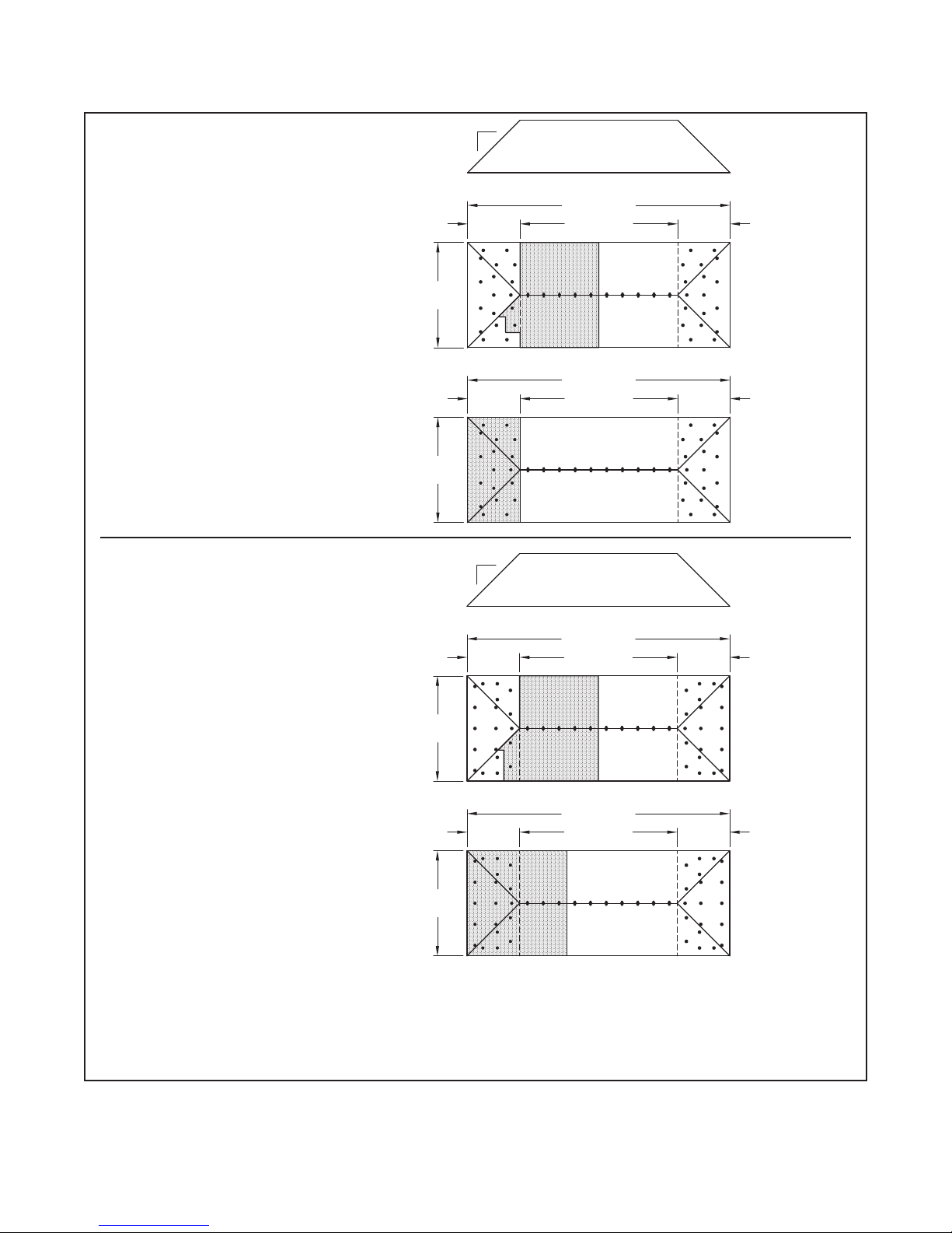
TFP610
(10,2 m)
12
Calculation 1
Calculation 2
(10,2 m)
(10,2 m)
Calculation 2
(10,2 m)
12
Calculation 1
Page 26 of 28
MODEL AP SPRINKLERS
WET PIPE SYSTEM
(Refer to Figure 20-B-3)
Calculation 1:
Calculate the most demanding five BB
Sprinklers plus the two most demanding AP Sprinklers.
Calculation 2:
Calculate the most demanding area
up to 1500 ft² having AP Sprinklers. In
this case the design area will be 800 ft²
(40 ft × 20 ft)
Use the most demanding calculation to
prove the adequacy of the water supply.
Where AP Sprinklers are utilized, CPVC
pipe may be used to supply the AP
Sprinklers, as well as the ceiling sprinklers below the AP Sprinklers. For more
information, see Page 6.
STANDARD SPRAY SPRINKLERS
WET PIPE SYSTEM
(Ref. Figure 20-C-3)
Calculation 1:
Calculate the most demanding five BB
Sprinklers plus the two most demanding Standard Spray Sprinklers.
Calculation 2:
Calculate the most demanding remote
design area, including all sprinklers
types, per NFPA 13 (i.e., area reduction
for quick response and 30% increase
for sloped ceilings). In this case the
theoretical design area is 1463 ft²
(1500 ft² × 0.75* × 1.3). The actual
design area, however, will need to be
1520 ft² to pick up the entire coverage
area of the last BB Sprinkler.
Use the most demanding calculation
to prove the adequacy of the water
supply.
Where Standard Sprinklers are utilized,
CPVC pipe CANNOT be used to supply
the Standard Spray Sprinklers or the
ceiling sprinklers below the Standard
Spray Sprinklers.
* A 25% reduction for 20 ft ceiling.
EXAMPLE FOR A WET PIPE SYSTEM HYDRAULIC DESIGN AREA COMPARISON
OF MODEL AP SPRINKLERS VERSES STANDARD SPRAY SPRINKLERS
WHERE MODEL AP OR STANDARD SPRAY SPRINKLERS ARE USED IN HIP AREAS
OUTSIDE THE SCOPE OF APPLICATION FOR MODEL BB BACK-TO-BACK SPRINKLERS
12
20'
(5,1 m)
40'
20'
(5,1 m)
40'
12
20'
(5,1 m)
40'
20'
(5,1 m)
40'
FIGURE 21
100' (25,4 m)
60' (15,2 m)
100' (25,4 m)
60' (15,2 m)
100' (25,4 m)
60' (15,2 m)
100' (25,4 m)
60' (15,2 m)
20'
(5,1 m)
20'
(5,1 m)
20'
(5,1 m)
20'
(5,1 m)
Page 27
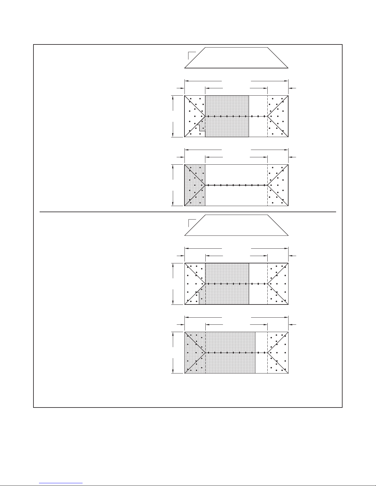
TFP610
(10,2 m)
Calculation 2
(10,2 m)
Calculation 1
12
(10,2 m)
(10,2 m)
12
Calculation 2
Calculation 1
Page 27 of 28
12
MODEL AP SPRINKLERS DRY PIPE
SYSTEM
(Ref. Figure 20-B-3)
Calculation 1:
Calculate the most demanding seven
BB Sprinklers plus the two most
demanding AP Sprinklers.
Calculation 2:
Calculate the most demanding area
up to 1950 ft2 having AP Sprinklers. In
this case the design area will be 800 ft2
(40 ft x 20 ft)
Use the most demanding calculation to
prove the adequacy of the water supply.
STANDARD SPRAY SPRINKLERS
DRY PIPE SYSTEM
(Ref. Figure 20-C-3)
Calculation 1:
Calculate the most demanding seven BB
Sprinklers plus the two most demanding
Standard Spray Sprinklers.
Calculation 2:
Calculate the most demanding remote
design area, including all sprinklers
types, as per NFPA 13. That is, 30%
increase for sloped ceilings and 30%
increase for dry systems. In this case
the theoretical design area will be
2535 ft² (1500 ft² × 1.3 × 1.3). The actual
design area, however, will need to be
2720 ft² to pick up the entire coverage
area of the last BB Sprinkler.
Use the most demanding calculation to
prove the adequacy of the water supply.
40'
40'
40'
40'
12
20'
(5,1 m)
20'
(5,1 m)
20'
(5,1 m)
20'
(5,1 m)
100' (25,4 m)
60' (15,2 m)
100' (25,4 m)
60' (15,2 m)
100' (25,4 m)
60' (15,2 m)
100' (25,4 m)
60' (15,2 m)
20'
(5,1 m)
20'
(5,1 m)
20'
(5,1 m)
20'
(5,1 m)
EXAMPLE FOR A DRY PIPE SYSTEM HYDRAULIC DESIGN AREA COMPARISON
OF MODEL AP SPRINKLERS VERSES STANDARD SPRAY SPRINKLERS
WHERE MODEL AP OR STANDARD SPRAY SPRINKLERS ARE USED IN HIP AREAS
OUTSIDE THE SCOPE OF APPLICATION FOR MODEL BB BACK-TO-BACK SPRINKLERS
FIGURE 22
Page 28

TFP610
Page 28 of 28
1400 Pennbr ook Parkway, Lansdale, PA 19446 | Telephone +1-215-362-0700
© 2018 John son Control s. All right s reserved. A ll specifica tions and ot her informa tion shown wer e current as o f document rev ision date an d are subject t o change wit hout notice.
NATIONAL FIRE P ROTECTION ASSOCIATIO N and NFPA are register ed trademarks of N ational Fire Protec tion Associati on;
TEFLON is a regi stered tradema rk of DuPont; BLA ZEMASTER is a regis tered trademark o f The Lubrizol Cor poration
 Loading...